Additional parts mounted on the fore cross beam are necessary when driving in the tacking on acute course, while the water descends the leeward swiercz. The rest of the time they are raised and held by rope loops tied to the aft cross beam. In the working position is drawn swiercz rubber harness from the expander to the nose of a kayak. The area of each shvartza sufficient to tacking trimaran was almost no drift.
Fig. 1. A schooner is a trimaran on the basis of kayaks “Taimen-2” (on the top view of the mast conventionally not shown):
1 — rudder, 2 — thrust steering, 3 — grotto, 4 — FLC, 5 — topenant boom, 6 boom, 7 sheet, 8 – tackle for the adjustment of the belly, 9 — cups of masts, 10 — swiercz right (in position), 11 – floats for side, 12 — ring clamp rope for fastening braces svircev, 13 — attachment of braces svircev, 14 — cabin removable, 15 — staysail auxiliary, 16 — rumple, 17 — the hinge attachment of the rudder to the tiller, inflatable 18 “logs,” the 19—additional parts left (in raised position), 20 — guy svarca, 21 — seat aft, 22 “kolduny”.
Fig. 2. Power frame (top view):
1 — section of the Central cross beam ( D16T, pipe 40×1,5, L1500, 2 PCs.), 2 — seat side (plywood s8, 1110×150, 2), 3 — reinforced side of the seat (D16T, pipe 16×1,5, L1000, 2 PCs.), 4 — node fixing the diagonal beams and the side of the seat to the cross beam, section 5 of the extreme transverse beam (4 PCs.), 6 — beam diagonal aft L-shaped attachment (AMG, pipe 25×1,5, L1150, 2 PCs.) 7 — fixing unit diagonal beams to mactopia glass, 8 — Cup mast (AMG, tube 52×1, L500, 4-piece), 9 — mount mast Cup to the bulkhead, the 10 — node retraction of the diagonal beams L-shaped attachment 11 — beam for mounting the grotto-sheet, 12 — beam diagonal of the nose L-shaped attachment (AMG, pipe 25×1,5, L1170, 2), 13 — knot fastening the cross beam to the gunwale.
Fig. 3. Mast Cup:
1 clamp-fastening diagonal beams, 2 — area-mount glass to the frame, 3 — clamp-mount area, 4 — tube wooden, 5,8 — screws, 6 — yoke-mount glass to the keel, 7 — stud fastening frame on the keel, 9 – M6 screw, 10 — bracket, 11 — a layer of duct tape, 12 — Cup.
Fig. 4. Install the mast Cup on the power set of kayaks (the attachment of the stringers on the frame conventionally not shown):
I should put on the glass clamp to the keel, II — to put in the frame, III — poking, IV — lower vaterveys so that the clip simultaneously entered into a gap at the area of attachment and in an appropriate bracket on the frame.
Fig. 5. The cross beam of the trimaran:
1 — section of the Central cross beam (for nasal — tube 40x 1,5, L1500; feed — tube 45×1,5, L1500), 2 — extreme section cross beam (for nasal — tube 36×1,5, Ь750; feed rough 40×1,5,1-750), 3 — bracket fastening the cross beam to the rail, 4 — rail, 5 — strut Y-shaped, 6 — fixing unit svircev on the bow beam, 7 — pin (rod 05), 8 — hook (rod Ø 6), 9 — stringer float, 10 — float 11 — pocket wood in the last sections of the nasal beams.
Fig. 6. The scheme of fastening the cross beam to the gunwale and keel:
1 — cross-beam, 2 clamp-fastening of the beam to the bracket 3 — clip 4 — rail and 5 — clip bulkhead, 6 — stand Y-shaped (tube 16x 1,5, L520), 7 — area-mount Y-shaped strut to the keel, 8 keel.
Fig. 7. Bracket of fastening of cross-beams to the bulwarks (the A — fore, B aft):
1 — cross-beam, 2 — clamp (AMG), 3 — area (D16), 4— plate side (D16T), 5 — screw M3, 6,7 — M6 screws, 8 — slot bracket of the frame, 9 the bulwark, 10 — M6 screws attaching the Y-shaped strut to the bracket 11 is a cutout in the side plate for support on the frame, 12 — frame, 13 —clamp frame.
Fig. 8. The attachment point of the diagonal beam and outboard cross beam to:
1 — seat, 2 – beam diagonal, 3 clamp, 4 — beam cross-section, 5 — panel dural, 6 – tube reinforcing, 7 — screws.
Fig. 9. The clamping svarca to the fore beam:
1 — beam bow, 2 clamp attachment point (made of anodized aluminum, lisg 1), 3 – insert a wooden, 4-lug (wooden block 40×40, L140), 5 – screw M6 b — nut M10 7 washer (aluminum), 8 — washers (Teflon) 9 — swiercz, 10—bolt M10.
Fig. 10. Additional parts:
1 — hole for M10 screws, 2 — pads duralumin with two sides svarca, 3 — rivet Ø 4, 4 — screw MB for the attachment of braces, 5 — pins are made of metal.
Fig. 11. Steering gear:
1 — the hull of kayaks, 2 — end feed, 3 — box regular steering, 4 — pad reinforcing (duralumin, sheet s), 5 — area of attachment of the tiller, b — axis rudder (bolt M8), 7 — rudder 8 — hole Carlina, 9 — M6 screws.
Fig. 12. Lateral float:
I — stringer (D16T, pipe 16×1,5), 2 — bow-beam, 3 — beam aft, 4 — way fitting.
Fig. 13. Mast:
1 —the bottom section (D16T, pipe 45×1,5, L1500), 2 — the clip on the bottom bow, 3 — bow bottom (steel rod Ø 8), 4 — cross-duck (D16T, pipe 16x 1,5, L100), 5,8,10 — ear wooden, 6 — section average (D16T, pipe 40×1,5, L1500), 7 — screws M6, 9 — top section (D16T, pipe 32×1,5, L1300), 11 — ring for the tether, 12 — shackle upper (steel rod Ø 8) 13 nut M8 14 M6 screws, 15 lock, 16 — tube wood.
Fig. 14. Geek:
Section 1 front (D16T, pipe 32×1,5), 2 — section rear (D16T, pipe 25×1,5), 3—shackle (steel rod Ø 6), 4 — pin, 5 — tube wooden, 6 — hole bolt glass geek.
Fig. 15. Glass geek:
1 — glass (AMG, pipe 52x 1), 2 — M10 bolt (head cut down), 3 — nut M10, 4 — screw with nut M6, 5 — plate (duralumin. sheet s3).
Trimaran centered on bringing to the wind. Regular rudder kayaks replaced by a homemade larger. In a strong wind load on the wheel and thus on the tiller is significant, therefore, to secure the nosing to the feed shell kayaks are made in the first through hole through which the bolt it is connected to the sternpost. Regular tiller replaced with a longer, tapered made of dural tube. Rope tie rods also replaced on the dural tube is passing over the bulwarks along the entire cockpit. This allows the steering to move freely in the cockpit and otkrenivat, not letting go of the control.
In calm weather you can use the paddle sitting in the aft cockpit on the bench. Mount aft cross beam allows you to paddle like a kayak, and a single blade paddle.
Under the keel frame fit case, three children’s inflatable “logs” — it improves the handling characteristics of the trimaran, and also increases the volume of the body and refines its contours. With the rapid movement of the feed vessel is generally at-Teplovaya to the level of the deck, and that water has not got into the cockpit, in the stern along the sides, between the shell and the power set is located even on the “log” in a protective case. They increase the freeboard and increase the comfort of sailing — boat less zabryzgivaya. The “logs” pressureviagra a nylon rope to the metal rings on the deck.
Trimaran is armed with two identical sails of the “swift” with the bent back upper part of the mast. Mast free-standing in the glasses-stash (Fig.Z) that are elements of the power frame is located in the bow and stern of the cockpit from the first and fourth frames. Possibility of installation of additional glasses that allows you to easily change the layout of the sail. So, to improve the efficiency of looked like a sharp courses, the mainmast is rearranged in an extra glass on the aft cross beam at the third frame. To reduce sail in strong wind resistant single mast retracts, and the second rearranged in an additional glass mounted on the fore cross beam from Yorogo the frame. Sails slab is not provided. Priedayutsya squalls with sails set in the feathered position.
In weak and moderate wind on the fore-mast it is possible to raise light utility staysail, and the fore-mast to support removable cables. When driving the tack is attached only the windward guy and leeward running end automatically given.
The sails are double — layered with small “hammer” on the back foot, supported by short battens. This sail fits over the mast pocket, and then fastened the boom. Curved geeks don’t spoil the profile of the sail, and their design allows for fine tuning of the sails to change the location of the belly of the sail at the height of the mast.
In the nose of the cockpit between the first and second frames can be installed in the cockpit — a convenient shelter from wind and rain. Moving against the waves on sharp courses this cabin protects the cockpit from flooding, and the crew from spray.
Now more detail about the main parts of the structure of the trimaran.
Mounting hardware mast mast serve cups (Fig.Z and 4). They are included in the power set of the emerging kayaks and distribute the mast load on the entire hull. The clamp mounts to the frame has a bend from dural plate and is bolted to the glass. To avoid slipping, under the clamp pamotan layer of textile tape. In the supporting corner-cut rectangular slot B1 which includes the bracket at the end of the vaterveys transverse kit kayaks. A glass area attached additional clamp. Wooden plug tightly inserted in a glass epoxy resin and fixed with a screw. When assembling the kayaks, the glass is installed on the keel with a strap-cradle and fastened it with a hairpin, along with the frames. Installation procedure mast Cup shown in figure 4. The ends of the diagonal beams that form the top of the L-shaped mounts, flattened and tightened the bolt. The cross beam (Fig.5) attached to the bulwarks brackets (Fig.7). In order to remove unnecessary tension in the ribs and increase the rigidity of the structure, they are backed by the bottom U-shaped racks (Fig.6) connecting the power frame with the keel.
Side seats (Fig.8) reinforced dural tubes, rigidly secured at their lower planes. Seat are connected by transverse beams and clamps. The clamps pulled and diagonal /1-shaped beams.
Additional parts (Fig.9 and 10) have an asymmetrical profile and is made from two boards glued face “epoxy”. For the strength of bonding at the ends of the boards drilled socket in which is inserted metal pins. After processing additional parts is impregnated with linseed oil and varnished. For the sake of increasing the effectiveness of their action wets the surface of each shvartza polished.
The rudder (Fig. 11) of the two riveted duralumin sheets 1.5 mm thick. the Length of the standard tiller has been increased, for this purpose its ends are smoothed with a file and they are pre-punched tapered pipe 25×1,5 mm. the Ends of the new tiller is rounded and drilled holes for mounting rods (of duralumin tubes with a diameter of 10 mm), which stretch along the entire cockpit and pass through the guides on the brackets attaching the beams to the bulwarks. The steering box is reinforced with additional plates. Axis-rivet regular rudder drilled, instead a bolt M8. Nut it is fixed by cotter pin, to prevent inadvertent loosening.
Side floats (Fig. 12) is laminated of rubberized fabric. The bonding technology is described in detail in the book by V. Peregudova.
Each mast (Fig. 13) consists of three sections, inserted into one another and fastened with screws. To increase strength in the lower section half of its length, and in the lower parts of the middle and upper sections inserted wooden inserts. A few rings in the upper section serve to reduce the bending loads on the mast from the halyard when the sail. As it is very hard to find pipes are needed, the theoretically calculated diameter, in the joints of the sections to ensure rigidity it is possible to use the “shirt” of fiberglass, impregnated with epoxy resin. For fastening the backstay-bolina the lower luff of the sail, as well as for wiring and mounting gear, regulating the belly of the sail, designed lower arc. It is attached to the lower section of the mast with the clamp, which has a bend from the plate soft alloy AMG thickness of 1 mm. For the strength of the plate is a duplicate. Top bow is for the posting of the tether and fastening the upper end of topenant. This headband is made removable and is fixed in the holes on the top section of the mast with a hairpin.
Gik (Fig.14) is assembled of two sections, inserted into one another and fixed with a hairpin. For strength the front section is made of profiled. A boom attached to the mast via a freely sliding on its lower section of the glass (Fig. 15), the front part of the boom, put on the bowl bolt and pulled the nut after the mast is put on a sail.
MAIN TECHNICAL CHARACTERISTICS
TRI
The area of Foca m2………3,3
Main sail area, m2…….. 3.3
Width, m………….. 2,8
Height, m…………… 4,2
The volume of one side
float, l…………. 90
Lots of additional
equipment, kg ……… 30
The build time by one person, h…..no more than 2.5
Sails (Fig. 16) made at home from fabric “TEC pen”. Choice of two-layer sails for beginners is preferable: it is much easier to obtain without wrinkles. However, we have to put up with a large amount of material: two sails Is about 50 m fabric width of 0.8 m.
Usually on the sails of the “swift” back foot concave. However, the production version of the “sickle” was not too difficult, but allowed us to make the sails larger at small length of the masts. “Hammer” is supported by five battens that are inserted into laderman and fixed them in regular believeme rubber bands. Armor made of wooden rulers student and for strength covered with duct tape. Location laderman is determined depending on the quality of the fabric.
In the manufacture of sails advisable to use the detailed recommendations contained in the book V. M. Peregudova. Sew directly on the frame structure formed by the mast, the boom and ropes, Bulanyi rear and bottom skinoren. All final dimensions are determined empirically. The following describes the operation for making a double-layered sail.
1. To make the mast, cables bulini of scateren, fire at their ends, a device to adjust the belly of the sail, the halyard, and ducks. Collect all frame gear for adjusting the belly and check their work.
2. Put the frame in the position of the zero belly. Measure the length of skinoren and determine the future size of the sail.
3. To mark the canvas, cut separate pieces to make the basic cloth with an adequate reserve for all Katarina (the cloth should be flat).
4. On each flag to make sheet corner (sew a reinforcing lining fabric — booty, sew eyelets, to strengthen the edges of panels bend tissue).
5. To make flowy and halawy the angle of the sails (to bend the upper and lower edges of the panels to strengthen them printed grosgrain ribbon or webbing).
6. Without removing the bow from the mast, fold together the left and right of the sail and fasten it Shkotovo corner of the bottom ogon bolina the back of the leech and the upper fire bolina bottom of foot; top of foot bolina back to fix the hand seam so that the fire played over the top edge of the sail.
7. To place the mast horizontally to adjust it to the situation of the middle belly of the sail, to sweep the place of the leech of the sail, podsalivaya both the cloth with pins. Try to get in the sheets there was no wrinkles and constrictions; if necessary, repeat the process of smachivaniya first. Bulge the belly should reach 7%, its maximum is located at a distance of 40% of the width of the sail from luff point; at the back of the leech of the sail should be flat.
8. To put the sail in the position of a small belly (2-3%) and repeat the operation smachivaniya to obtain a good shape of the sail in this mode. To do the same procedure to position a big belly (12%).
9. Changing the position of the belly, control the smoothness of the surface of the sail in all modes.
10. To remove the sail from the mast. To remove the pins from the back and bottom of scateren, to issue finally the front foot sewing machine seam. Bowline luff rear the better to grab in several places, hand-stitch. In the lower part of the front foot to sew skertic-quickdraw sails.
11. Re-place the sail on the mast to check his form in all modes of operation. If there are distortion, to dissolve the basting stitches, and repeat the operation smachivaniya rear and bottom skinoren.
12. To mark places laderman.
13. To remove the sail from the mast, and finally stitch the cloth line the back and bottom of skinoren and laderman.
In the process of operation sail wrinkles that have failed to remove when sewing, can disappear as a result of pulling tissue. In determining the location of the Shkotovo angle of the sail it is necessary to consider that domestic fabric is quite stretched.
Fig. 16. Double-layered sail “swift”:
1 — left panel, 2 — panel, right -, 3 — mast, 4 — bowline rear foot, 5 — foot rear, 6 — laderman, 7 — foot lower, 8 — lower edge of the sail, the 9 — ogon bolina bottom of foot, 10 — edge of the sail upper, 1 [ — ogon bolina hind foot, 12 — window in the sail to the axis of the boom 13, the eyelet 14, the lower bowline luff, 15 — hand suture, 16 — bout, 17 — seams of the panels. A — seam for the connection of panels B — valovyj the angle of the sails, In — halawy the angle of the sails, G — the look of the front of foot.
Fig. 17. The experimental setup of the sail on the fore-mast:
1 — hole in the luff of Foca, 2 — ring for wiring the jib halyard (fixed in the middle of the top section of the mast), 3 — ring for wiring the jib of the fpag, 4 — tether, 5 — gals, 6 — clamp mount vant, 7 — guy.
Fig. 18. Frame technique:
1 —the hull of kayaks, 2 — rail, 3 — beam bow-diagonal, 4 — Cup the foremast, 5 — spars front, 6 — slopes, 7 — beam bow, 8 — cross, 9 —M6 screws.
The auxiliary jib can be made from any lightweight material, soaking it in any composition that provides windproof. As shown, good stakely obtained from the plastic film and of cheap percale is impregnated with a solution Botswana in acetone.
Shown installation diagram makes it easy to raise and lower the jib on the fly from the cockpit. Lines removable cables are fixed to the forward cross beam.
To increase the comfort of travel on the trimaran, as well as additional security, along the sides of the inflatable secured to the bulwarks. They are made from an inflatable children’s “logs” (three each side) which are placed in pouches lightweight fabric and attached a nylon cord passed through rings (fit of the metal “carpet” rings) sewn to the deck of a kayak. To give the vessel a more aesthetic appearance from the nose and stern “logs” are closed pitches of fabric, which are sewn to the deck and pressureviagra from the top to the joists with diagonal fasteners.
The frame of the cutting (Fig. 18) is made of duralumin tubes with a diameter of 16 mm. Design ensures quick installation and removal. The awning of the deckhouse is fixed in the nose pitches on hooks or buttons. Fore-mast passes through the pocket and is Brocante, which prevents the penetration of water into the cockpit.
The process of operating a two-masted vessel not much more complicated than usual, and experience in the management of sails comes just after two or three training outputs. A big help in can bring permanent use of “evenly spaced” — ribbons of bright nylon or polyethylene, placed on wire racks on the bow cross beam. It is easy to determine the true wind direction regardless of the tack and to choose an optimal course of movement.
Going on a long hike, you should take care sealed bags for clothes and food, a few spare inflatable “logs”, anchor, mooring the end, repair kit and first aid kit. Not be amiss, and a reminder of lifejackets for all crew members.
A. EFIMOV
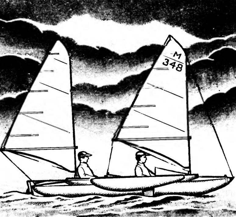
Recommend to read “Butterfly” on the waves The ultra-light international Moth class dinghy — the “Moth” (fig. 1, 2) is simple in design, easy to build, and possesses all the most important qualities of a racing boat — it is fast,... SPEAKERS IN A HURRY Existing acoustic system (as) furniture type mostly rather cumbersome and expensive. To use them when testing and setting the audio uncomfortable. And in ordinary surroundings while... 
 Whether on forces to build a yacht for the beginner to sailing matters, having in disposal only the materials from the stores “Do it yourself”? The main problem that he faced at the beginning of their labors, is the choice of design of the future vessel. Once a few years ago in a similar situation, I decided that the easiest way is to make the sailboat of the tourist serial portable kayaks. And of all the published canoe designs the most attractive seemed to me project boat-trimaran.