
 Many motorists, especially the owners of domestic vehicles has experienced all the “charms” winter operation “beloved horses”. Special “pleasure” — after frosty nights to bring to life the heart — the powerhouse. I have a giant of Russian car industry — “Eye”, so all my thoughts and efforts were directed to develop a system that allows you to quickly and efficiently prepare the engine to start, warm up underhood space. respectively, the battery and create, if possible, a comfortable environment in the vehicle. The advantages of such training are obvious: easier to start engine at any temperature; reducing consumption of gasoline at start-up and engine warming up, which is especially great in the cold season; increases battery life by reducing the starting current on a warm engine, increase the service life of the starter by reducing the wear on the bushings the armature and the life of the engine.
Especially nice to sit in the warm cabin, where the steering wheel can take, that is, bare hands, and the glass is not fogged. When storing the car in an unheated garage or outdoor Parking lot by using the proposed device will need only 15 — 20 minutes to prepare the car for the trip.
This system is designed for “Oki”, but with small alterations can be applied in any domestic vehicle.
To solve the problem I began with the analysis of similar systems installed on various vehicles. Unfortunately, domestic cars, if equipped with heaters, it is very primitive and ineffective. For example, heating of the engine oil through the dipstick, the installation in the case of special items or even turning on the headlights for heating the battery, etc.
In expensive cars this problem is usually solved more radically: with the circulation of pre-heated antifreeze. But the technical realization of this method under the conditions of ordinary personal garage is very problematic: it is necessary to external engine to build special plugs (“penny”) coated with a semiconducting composition for the wireless heating.
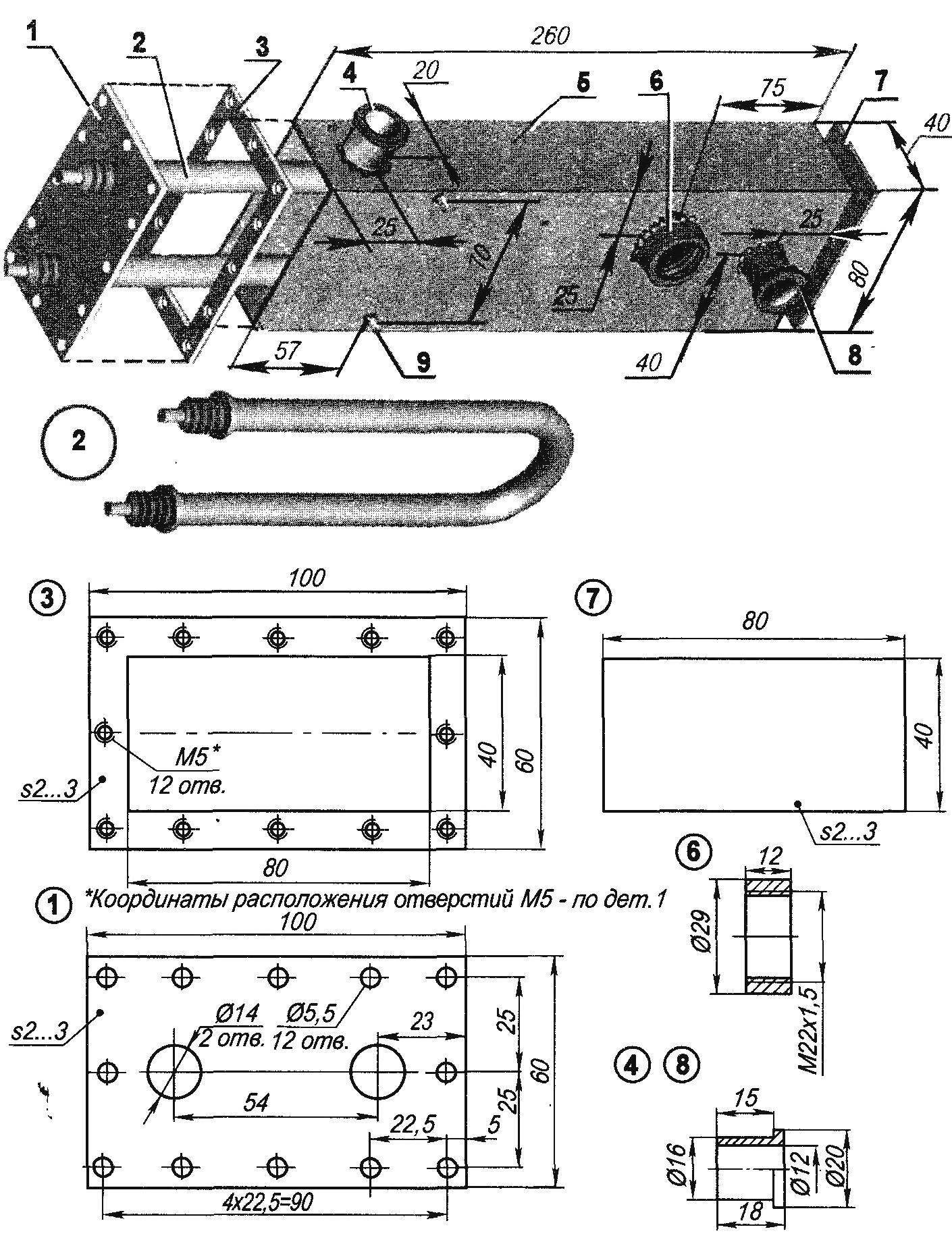
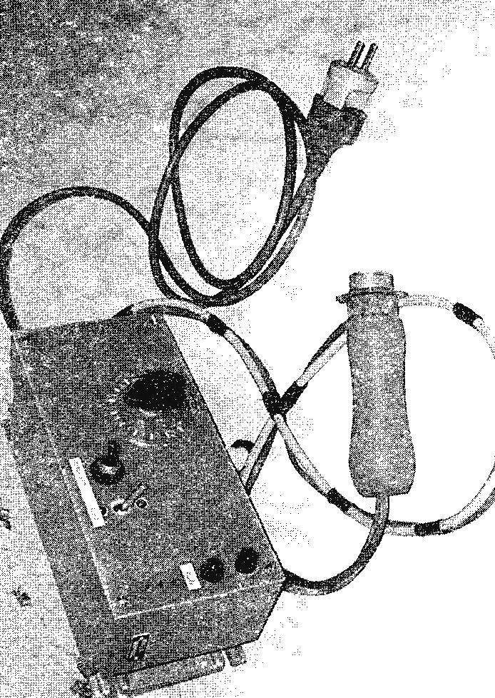
Heater:
1 — front cover (St3, the sheet s2 — 3); 2 — heater 1.5 kW; 3 — flange (St3, sheet — 3); 4,8 — ports (St3, pipe, rod 20); 5 — housing (St3; rectangular tube 80x40x2,5, L260); 6 — nozzle ; 7 — rear cover (St3, the sheet s2 — 3); 9 — mount the pump (stud M6, 2 PCs.).
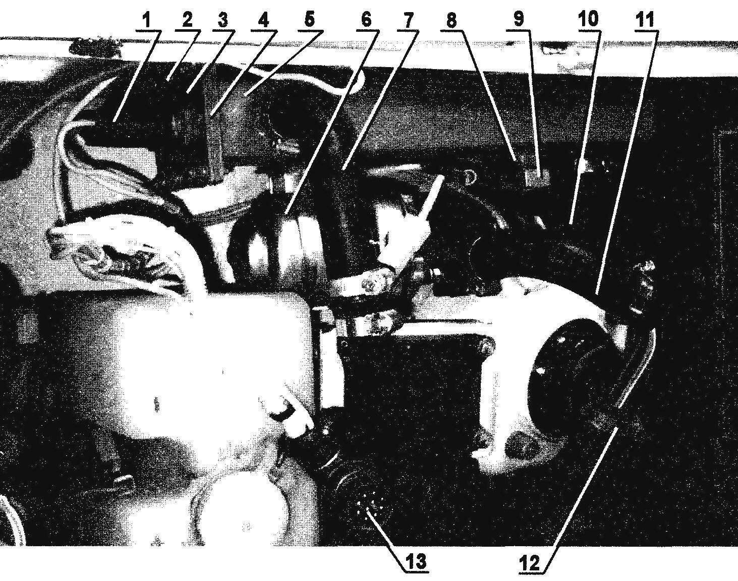
The system of winter heating of the car “Oka”:
1 — conclusions of the heating element—heating element; 2 — the cover of the heater (screw M5, 12 PCs); 3 front cover of the heater; 4 — front flange; 5 — heater; 6 — pump (on car “Gazelle); 7,10 — hoses supply/return coolant; 8 — fitting of the temperature sensor; 9 — temperature sensor (coolant any car 90°); 11 — hose pumps; 12 — clamp, hose (standard car, the number — as required); 13 —plug connector electronic control unit of the heating system.
As a result, for the basis I took a warm-up using antifreeze as coolant, but have implemented this principle in its own way, proceeding from available possibilities. The whole system is divided into two main nodes: the metal structure of the actual heater and the electronic unit providing the adjustment, work in the optimal mode, and emergency shutdown system in case of unusual situations.
The heater casing is a 260 mm cut rectangular steel tube cross-section 80×40 mm, with wall thickness 2.5 mm. One end is welded a dull flat lid and welded to the second flange-frame ,with 12 of the M5 threaded holes to which screws are required on the front cover with the Heater, put on heat-resistant sealant with the gasket. The power of heating element — 1.5 kW — is enough to service the engine capacity of 1.7 L.
On the housing side wall carbon-dioxide welding welded two socket for connecting hoses inlet and outlet coolant (when installing it is important not to confuse), fitting under a temperature sensor, two studs MB for mounting elettropompe (I have it from “Gazelle”) and two eyelets for attaching the entire structure to the wall of the engine compartment. Fully assembled heater checked for leaks and fixed with two screws to any convenient place under bonnet. It only remains to connect the two hoses in the gap between the “stove” and the engine block, and one corner the hose from the pump to the heater. The fixing clamps on the standard hoses.
The device operates in the following sequence. After switching on the heater begins to warm the antifreeze, the pump drives it into the engine, heating the engine block, goes in a small circle, as the thermostat is closed, the pumps in the stove of the radiator and returns to the heater. Thus, the result of this system heats up the tank, battery and engine compartment and provided at the time of start of flow of the engine heated air.
The electronic part of the device, as mentioned above, is designed to provide the normal functioning and security of the whole system, working from a network 220 V. First of all, the temperature sensor is adjusted to a maximum temperature of 90°C, it exceeded includes relay R1 turn off the power to the generator, performed on the transistor VТ 1, and heating stops.
In series with the normally closed contact P1 is installed normally open contact of the reed switch. The winding of the reed switch connected in series with the motor pump. Because of the small amount of heater operation with Heater without the pump impossible, therefore, if there is an open in the motor circuit of the pump, the coil of the reed switch will takes out his contacts open, the generator will stop working, the heater will stop.
The following case. If elektropompa for any reason will stop, the current in the circuit will increase sharply, will burn out the fuse FU3, the winding of the reed switch again takes out, the contacts open, de-energized power generator, the heater will stop. This protects the device from possible trouble.
Signal light EL1 indicates the fan to a heater in the car, and EL2 — elettropompe. Now about the electrics of the developed system. It is divided into two components. The elements of the first part are mounted directly on the vehicle components. Heater installed: heater power of 1.5 kW.; pump, designed for a voltage of 12 V and supply current of 2.7 A; temperature sensor with normally open contact from any car with a temperature 80 — 90°C. Also from the electric motor to a heater of the passenger compartment (12 V, current consumption 1.5 A) output two cables. All conclusions of the above equipment on any soldered connector, in accordance with the scheme.
Separately in a suitable housing surface mounting is going electronic circuit which operates as follows: when enabled, ЅА1 10 amp fuse FU2 voltage transmitted to the voltage regulator, assembled in odnomomentno transistor VT1.
The regulator plays a major role in experimental selection of the degree of heating of antifreeze depending on the make of the car and the ambient temperature. In this case, the heating of the Heater can be adjusted from minimum to maximum, depending on its power.
Transistor VT1 provides the opening angle of the thyristors VS1 and VS2. Charging of capacitor C1 occurs through the resistors R2 and R4. At a certain value of the voltage on the capacitor C1 the transistor VT1 and the short pulse passes through the winding I of the transformer TP2. Depending on the phase of the mains voltage is displayed alternately thyristors VS1 or VS2. Changing the charge rate of the capacitor C1 variable resistor R4 regulates the opening angle of the thyristors and therefore the power in the load, in our case, PETN. Thyristors mounted on heat sinks with minimum area of 150 cm2 each.
The regulator after the quenching resistance R1 passes through the normally open contacts of the reed switch and normally closed relay contacts R1 (it is necessary because the contacts of the car switch is normally open).
When the maximum temperature of the antifreeze, marked on the sensor housing, its contacts closed, relay R1 will work and break the supply circuit of the regulator. Thyristors VS1 and VS2 will be closed, heating of the Heater stops. As the cooling of the antifreeze temperature will fall, the temperature sensor will break the circuit, R1 will work and supply power to the controller will start heating. The cycle will repeat.
The power of the pump is carried out through the winding III (12) of the transformer TR1. Through a fuse FU3 4 A and the coil L1 of the reed switch goes to the motor pump with an operating current of 2.7 A. When a disaster occurs, for example, in case of overload of the pump or breakage in its circuit, the current through the winding of the reed switch will not go, its contacts will open and stop operation of the generator on the transistor VT1, the heating of the heating element will stop.
Fan cooking interior is forcedly enabled switch SA2, although you can put any timer to switch after 10 to 15 minutes (the time required to heat the engine block). The connection of the fan motor conveniently carried out without dismantling, by connecting one wire to the switch on the panel of the vehicle, and the second to ground.
Schematic diagram of the system of the winter heated car
A few words about the components. The single junction transistor VT1 — КТ117А or КТ117В ; Zener VD6 — any designed for voltage 18 — 22 V and a current of 20 mA (two series-connected Д814Д); the bridge rectifier VD7 diode 402, 405 with any letters; VD1 — VD5 — any designed for a current of 5 A; the capacitor C1 with a small thermal coefficient of capacitance type K73-24, K73-17; the relay R1 is any 24 V contacts designed for a load not less than 5 A; reed relays — homemade with a wound on his body 8 — 10 turns of wire PEL-1-0.8; transformer Tr 1 — any 220 with the secondary windings on 12Вх5А and 24Вх200 mA; TP2 — any pulse type MIT-4, or improvised on a ferrite ring 20x10x6 mm brand 2000NM, all the windings of 40 turns of wire sew — 1 — 0,31.
Setting is the selection of R2 for maximum power in the load. Disconnect the control electrode of one of the thyristors. Instead of load (Rh) include the incandescent lamp. If necessary, change the ends of the windings check the control electrode of the thyristor. Repeat the operation on the second thyristor, disabling verified. Connect both of the control electrode. The lamp should smoothly change the illumination from minimum to maximum.
To verify that the temperature sensor is shorted perimysium his contacts: the load must be switched off. After the test jumper is removed.
This preparation of the system operation can be considered finished.
Happy journey!
V. ZHELEZNYAKOV, Volgograd
Recommend to read
 FOLDING GYM CLASS
A large army of fans daily sits down to the TV screens to watch fights nimble, hardy, courageous. And among viewers — its most direct and most react violently to stressful events... TRAILER FOR “JUPITER”
I have been engaged in creating various devices to facilitate work on the homestead plot for many years. However, I have not yet presented my developments to the readers' judgment; this is...
