Many motorists, especially owners of domestic cars, have experienced all the “joys” of winter operation of their beloved “steeds” firsthand. A particular “pleasure” is bringing the heart—the “fiery engine”—back to life after a frosty night. I own a giant of Russian automaking—the Oka—so all my thoughts and efforts went into developing a system that would make it possible to prepare the engine for starting fairly quickly and effectively, warm the underhood space and thus the battery, and create comfortable conditions in the passenger compartment where possible. The advantages of such preparation are obvious: easier engine starting at any temperature; reduced fuel consumption during starting and warm-up, which is especially high in cold weather; longer battery life thanks to lower cranking current on a warm engine; increased starter life due to reduced armature bushing wear and increased engine life.
It is especially pleasant to get into a warm cabin where you can take the steering wheel, so to speak, with bare hands, and the windows are not fogged. When the car is kept in an unheated garage or in an open parking lot, the proposed device will take only 15–20 minutes to prepare the car for a trip.
This system was developed for the Oka, but with minor modifications it can be used on any domestic car.
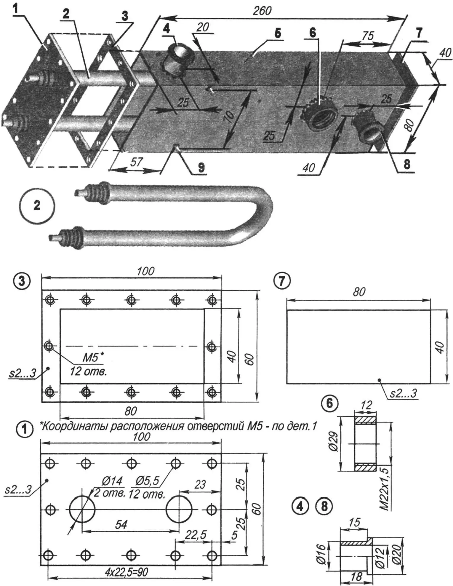
1 — front cover (St3, sheet s2–3); 2 — heating element 1.5 kW; 3 — flange (St3, sheet s2–3); 4,8 — pipes (St3, tube, bar 20); 5 — body (St3; rectangular tube 80x40x2.5, L260); 6 — nipple; 7 — rear cover (St3, sheet s2–3); 9 — pump mounting (M6 stud, 2 pcs.).
I started solving the problem by analyzing similar systems installed on various vehicles. Unfortunately, domestic cars, when equipped with heaters at all, have rather primitive and inefficient ones—for example, heating engine oil through the dipstick, installing special elements in the crankcase, or even briefly turning on the headlights to warm the battery, etc.
In expensive imported cars this task is usually solved more radically: by circulating preheated coolant. But implementing this approach in an ordinary home garage is very problematic: special plugs (“pads”) coated with a semiconductor compound for wireless heating must be fitted into the engine water jacket.
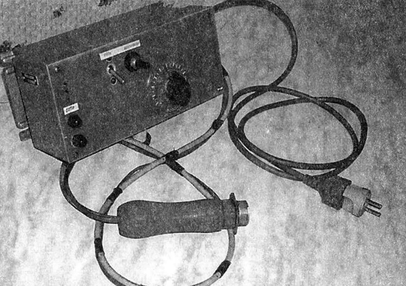
As a result I took heating by coolant as the basis, but implemented this principle in my own way, according to what was available. The whole system is divided into two main units: the metal structure of the heater itself and an electronic unit that provides setup, operation in optimal mode, and emergency shutdown of the system in abnormal situations.
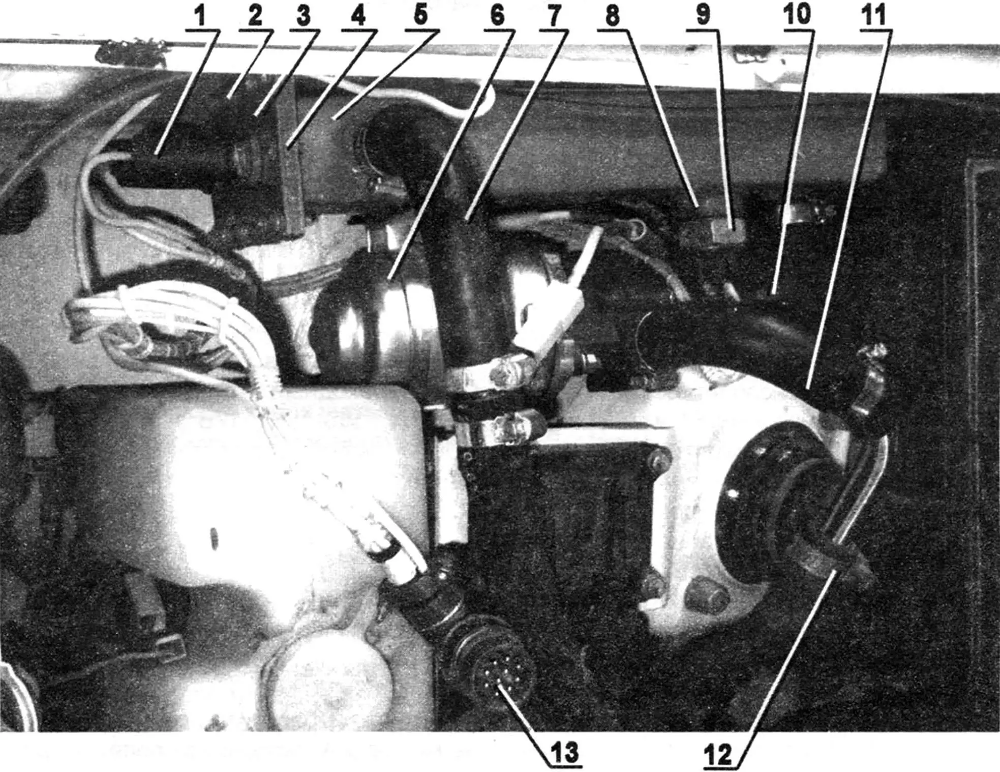
1 — heating element (TEN) terminals; 2 — heater cover mounting (M5 screw, 12 pcs.); 3 — heater front cover; 4 — front flange; 5 — heater body;
6 — pump (from Gazel vehicle); 7,10 — coolant supply/return hoses; 8 — temperature sensor nipple; 9 — coolant temperature sensor (any automotive, 90°C); 11 — pump hose; 12 — hose clamp (standard automotive, as needed); 13 — control unit connector.
The heater body is a 260 mm length of rectangular steel tube 80×40 mm in section with 2.5 mm wall thickness. One end is welded shut with a flat cover, and to the other a flange frame with 12 M5 threaded holes is welded; the front cover with the heating element, seated on heat-resistant sealant with a gasket, is bolted to it. Heating element power is 1.5 kW—enough to serve an engine of 1.7 L.
Two pipes for coolant supply and return hoses are welded to the side walls of the body by CO₂ welding (do not mix them up when installing), a nipple for the temperature sensor, two M6 studs for mounting the electric pump (mine is from a Gazel), and two lugs for mounting the whole assembly to the engine bay wall. The fully assembled heater is checked for leaks and fixed with two screws in any convenient place in the underhood space. All that remains is to connect two hoses in the break between the heater core and the engine block and one angled hose from the pump to the preheater. Hose clamps are standard.
The device operates as follows. When switched on, the heating element warms the coolant, the pump pushes it into the engine, heating the cylinder block; it goes in a small loop because the thermostat is closed, feeds the cabin heater core, and returns to the preheater. Thus the system heats the reservoir itself, the battery, and the underhood space, and ensures that preheated air reaches the engine at start-up.
The electronic part of the device, as mentioned above, is intended to ensure normal operation and safety of the whole system powered from 220 V mains. First, the temperature sensor, set for a maximum of 90°C, when that is exceeded energizes relay P1, which cuts power to the generator built around transistor VT1, and heating stops.
In series with the normally closed contact of P1 is the normally open contact of a reed switch. The reed coil is in series with the pump motor. Because of the small heater volume, running the heating element without the pump is not possible, so if there is an open in the pump motor circuit, the reed coil will be de-energized, its contacts will open, the generator will stop, and heating will cease.
Another case: if the electric pump stops for any reason, current in the circuit will rise sharply, fuse FU3 will blow, the reed coil will again be de-energized, contacts will open, cutting power to the generator, and heating will stop. This protects the device from possible mishaps.
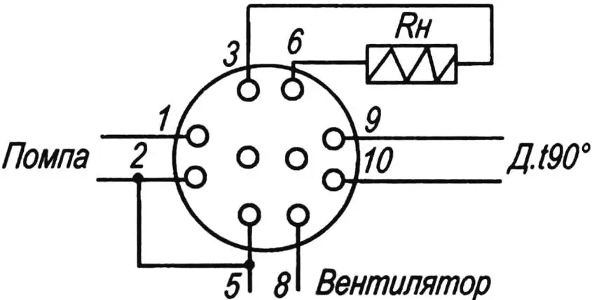
Indicator lamp EL1 indicates operation of the cabin heater fan, and EL2 the electric pump. Now about the electrical side of the developed system. It is split into two parts. The first part is mounted directly on the vehicle. On the preheater are: a 1.5 kW heating element; a pump rated 12 V, 2.7 A; a temperature sensor with normally open contact from any car, trip 80–90°C. Two wires are also brought out from the cabin heater motor (12 V, 1.5 A). All leads of the above equipment are terminated on a connector according to the diagram.
The electronic circuit is assembled separately in a suitable enclosure by point-to-point wiring and works as follows: when SA1 is switched on, voltage is applied through 10 A fuse FU2 to the voltage regulator built on unijunction transistor VT1.
The regulator plays the main role in experimentally matching the degree of coolant heating to the car model and ambient temperature. In this case heating of the element can be adjusted from minimum to maximum depending on its power. Transistor VT1 sets the firing angle of thyristors VS1 and VS2. Capacitor C1 charges through resistors R2 and R4. At a certain voltage on C1, VT1 turns on and a short pulse goes through winding I of transformer TR2. Depending on the mains phase, thyristors VS1 or VS2 turn on in turn. By varying the charge rate of C1 with variable resistor R4, the thyristor firing angle and thus the load power—here the heating element—is adjusted. Thyristors are mounted on heatsinks of at least 150 cm2 each.
Regulator supply, after dropping resistor R1, goes through the normally open contacts of the reed switch and the normally closed contacts of relay P1 (needed because the automotive sensor contacts are normally open).
When the maximum coolant temperature marked on the sensor body is reached, its contacts close, relay P1 operates and opens the regulator supply. Thyristors VS1 and VS2 turn off and heating stops. As the coolant cools, temperature drops, the sensor opens the circuit, P1 releases and applies supply to the regulator, and heating starts again. The cycle repeats.
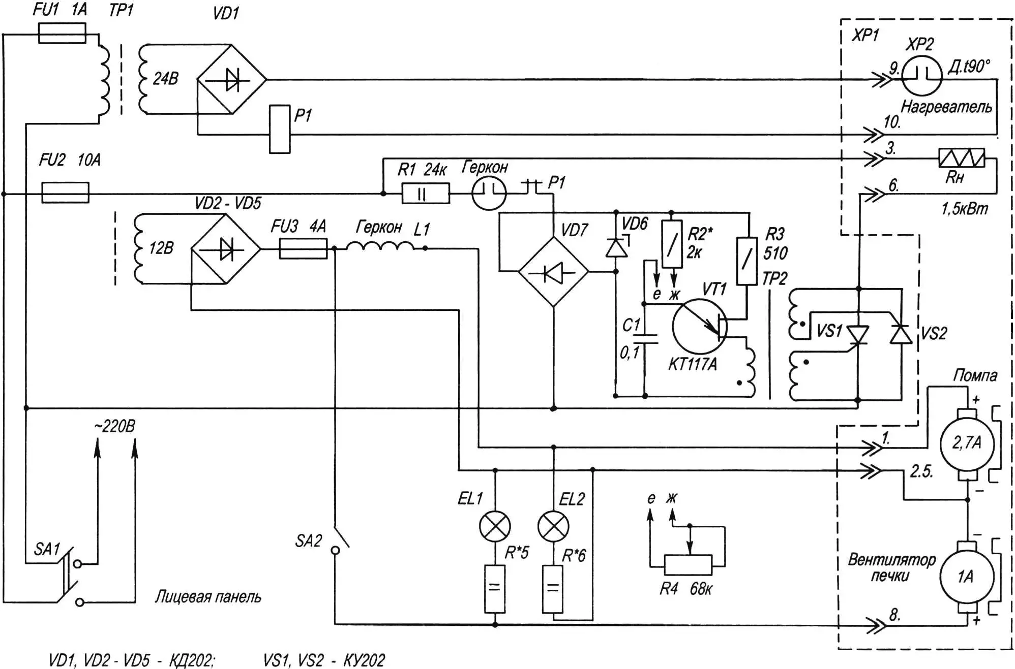
The pump is powered from winding III (12 V) of transformer TR1. Through 4 A fuse FU3 and reed coil L1, power is fed to the pump motor (2.7 A). In an emergency—e.g. pump overload or open circuit—no current flows through the reed coil, its contacts open, the VT1 generator stops, and heating stops.
The cabin heater fan is switched on manually by SA2, though any timer set to turn on after 10–15 minutes (time needed to warm the block) can be used. Connecting the fan motor is convenient without removing it: one wire to the panel switch, the other to ground.
A few words on the parts. Unijunction transistor VT1—KT117A or KT117B; zener VD6—any 18–22 V, 20 mA (or two D814D in series); rectifier bridge VD7 on 402, 405 diodes (any suffix); VD1–VD5—any 5 A; capacitor C1—low TCC type K73-24, K73-17; relay P1—any 24 V with contacts rated at least 5 A; reed relay—home-made with 8–10 turns of PEL-1-0.8 on its body; transformer TR1—any 220 V with secondaries 12 V×5 A and 24 V×200 mA; TR2—any pulse type MIT-4 or home-made on 20×10×6 mm 2000NM ferrite ring, 40 turns PEV-1-0.31 per winding.
Setup consists in selecting R2 for maximum load power. Disconnect one thyristor gate. Substitute a filament lamp for the load (Rh). If needed, swap the gate winding ends of the thyristor under test. Repeat for the second thyristor with the first disconnected. Connect both gates. The lamp should dim and brighten smoothly from minimum to maximum.
To check the temperature sensor, short its contacts: the load should turn off. Remove the short after testing.
With that, system preparation for use can be considered complete.
Safe travels!
«Modelist-Konstruktor» No. 10’2007, V. ZHELEZNYAKOV
Recommend to read
 CLOSURE TWO HOOK
Neat craftsman, working in his workshop, be sure to tie a safety apron — so as not to stain or damage clothing. And not to bother with a drawstring, it is better to attach to the apron... AMPHIBIAN AMPHIBIED
It’s tempting, isn’t it, to leave your house on a velomobile, get to the nearest body of water and, rolling down from a low bank, continue moving along the water? This will become possible...
