
 This year — 100 years since the birth of S. P. Korolev, the father of the Soviet space program, the outstanding designer of the first artificial satellites and spacecraft, the Creator of Russian strategic missiles. His interest in rocketry could arise even during his studies (he graduated in 1930 Bauman.Bauman), and finally strengthened with the creation of the public organization gird (Hoppy the study of reactive motion), where he developed and tested the first Soviet rocket “gird-9” and “gird-X”.
Later, on the basis of gird and Leningrad Gasdynamic laboratory created the Jet propulsion research Institute (RNII), in which great attention was paid to missile technology.
In RNII S. P. Korolev in 1934 directs the Department of cruise missiles; in 1936 tests they developed the first cruise missiles — anti-aircraft artillery managed 217 and 212.
Developed by here (headed by Yu. a. Pobedonostsev and G. E. Langemak) missiles were successfully tested in the battle of Khalkhin Gol while conducting combat operations against Japanese forces in 1939, and then was widely used during the great Patriotic war. Here was created and the famous jet “Katyusha”.
In September 1945, S. P. Korolev was sent to Germany in the composition of the team of specialists to familiarize themselves with captured German jet technology.
With the first samples, more precisely with the wreckage of German rocket technology, our specialists were able to see in the autumn of 1944 after the entry of the Soviet Army on the territory of Poland and the seizure of missile testing station. Even the wreckage of the missiles struck them. Hardly anyone was able then to imagine that you can create a liquid rocket engine and missile combat such gigantic size — height in four-storey building and a diameter of more than 1.5 m.
However, at the end of the war, Nazi Germany carried out a systematic bombardment of the UK, including London, ballistic missiles V-2 (A-4), which with a starting weight of over 13 tons were carried almost solid warhead at a range over 250 km. of Protection from these attacks was not because the speed of the rocket reached an incredible value of 1450 m/s Situation so alarmed the British that they had appealed to the Soviet government with the request to assist in obtaining intelligence information about weapons.
Soon intelligence found that the heads work on the rocket engineer Werner von Braun. It testing centre “peenemünde” is located on the island of Usedom on the Baltic sea. The Germans managed to mass-produce missiles A-4 in the underground plant “Mittelwerk” in Thuringia, which used the labor of prisoners of concentration camps. In December 1944 the British air force launched a massive bombing on the test center and destroyed it, but to get to the underground plant was impossible. After the war it became known that the Germans managed to produce about 5,000 missiles. Most of them were produced in England from launch sites located in Holland.
Creation V. von Braun collected from more than 30 thousand items, was a liquid rocket engine thrust 27 tons operating on liquid oxygen and 72% ethanol. Fuel supply was carried out turbopump Assembly, using a vapor-gas, which was formed as a special generator in the decomposition of hydrogen peroxide. Stability in flight was provided-developed aerodynamic stabilizer consisting of four consoles. This was controlled aerodynamic rudders, mounted at the ends of the stabilizer brackets, and gas rudders located behind the nozzle of liquid rocket engine (LRE). The main construction material was steel All the compartments missiles, except the warhead and tail consisted of a cross (ribs) and longitudinal (stringers and longerons) of the power components, covered by a casing and connected by riveting.
In the nose of the rocket were installed the warhead, carrying about 800 kg of explosives and fitted with impact fuse. The trail was located in instrument compartment control systems, telemetry and radio control, for installation and service of which there were four quick-release hatch in addition, in the compartment were mounted tear-off connectors for communication with ground equipment. Cable network linking the tail and instrument compartments were held outside the fuel.
On average, the fuel pod, were two drop tanks for fuel components And a tank of liquid oxygen was located behind the tank with fuel, consumable highway which passed inside of the oxidizer tank. In the tail section of the rocket housed a rocket engine with a turbopump Assembly (TNA), a gas generator, a toroidal tank of hydrogen peroxide, steering gears drive the gas and aerodynamic rudders, units and elements of the valve system fuel. On a pair of the stabilizer brackets were located antenna systems, telemetry and radio control.
After the war, the underground factory was captured by Americans, although he had to move to the Soviet zone of occupation. The allies received more than a hundred intact rockets that were exported to the U.S. moreover, they got the biggest trophy — the Wernher von Braun with a group of leading employees who chose to surrender to American troops.
In the Soviet zone of occupation was organized by the Institute “Nordhausen”, the staff requested the collection of technical information and search parts and components of rockets. His superior was appointed Lieutenant-General Lev Mikhailovich Gaidukov (former member of the Military Council of the guards mortar units), and chief engineer Sergey Pavlovich Korolyov, (recently released from prison). Before them stood a very difficult task, as the Americans, leaving the territory transferred to the Soviet occupation zone, almost all were taken, and what did not — destroyed. Our experts got scattered drawings, the remains of the missiles, individual components and assemblies.
Research R-1 E:
1 — head; 2 — the instrument compartment, 3 — telemetry antenna, 4 — cell, 5 — side containers; 6 — the rear compartment, 7 — console aerodynamic stabilizer; 8 — aerodynamic control surfaces; 9 — gas rudders; 10 — nozzle rocket engine RD-100.
I — welding seam; II — riveted joint (rivet round head); III — overlap of panels; IV — rivet joint (rivet with countersunk head); V — round head screws
As a result, complicated hard work of parts and assemblies found in the warehouses of different companies in Germany, Czechoslovakia and Poland, has gathered 29 of the rockets, completely rebuilt the design documentation, instructions, and also prepared 10 sets of parts for the Assembly of missiles in the USSR.
The staff of the Institute “Nordhausen” was the designer of rocket engines Valentin Petrovich Glushko. Under his leadership were organized and conducted bench testing of rocket engine rocket A-4. They showed that the engine can be boost up to 37 and even up to 43 tons of thrust. To accelerate the adoption of new weapons was formed a special military unit artillery brigade of special purpose.
Attaching great importance to enhancing the defense of our country, in may 1946, the government issued a decree on the development of missile technology. Had to create a new industry. Work on the creation of domestic missiles were concentrated in the Department No. 3 of the new Institute NII-88 of the Ministry of armament (now TsNIIMash). The head of Department and Chief designer of the missile, designated R-1, 9 August 1946 he was assigned to the S. P. Korolev. The engine development was headed by V. P. Glushko, control devices — V. I. Kuznetsov and Apilogin, radio systems, M. S. Ryazansky. The chief designer of the ground equipment was appointed V. P. Barmin. For testing missiles created the State Central test site of the Ministry of defense, located in the interfluve of the Volga and Akhtuba, now known as the cosmodrome Kapustin Yar.
In the spring of 1947 S. P. Korolev proposed to conduct experimental launches of missiles of the German A-4 for acquisition and accumulation of experience. To ensure the realization of these works was formed by a special train, consisting of 72 wagons for different purposes.
The first launch took place on 18 October 1947 in October-November, 11 rockets were fired successfully — only 5. Causes of accidents were engine failures, control system, leaky fuel lines, bad designs. These findings and about such statistics were kept and found in Germany, the test report A-4, who testified about the low reliability of the rocket by about 60%.
Employees at NII-88 and the Department had lot of work on the issue of new technical documentation based on the use of domestic materials. Had to pick up the 86 grades of steel, 56 grades of non-ferrous metals, coatings, 159 non-metallic materials, etc. In the process of design work was necessary to resolve a number of deficiencies identified in the prototype design of the rocket to improve its reliability and to solve the problem of long-term storage of the product. For the first series of R-1 designers as possible to a short time, sought immediately to implement new technical solutions was substantially revised designs of the tail and instrument compartments with the purpose of gain and was increased refueling to achieve a range of up to 270 km.
17 Sep 1948 launched the first domestic ballistic missile long-range (BRDG) R-1.
This start-up started its flight tests. With the launch of the first batch of missiles was revealed a number of observations. The most unpleasant was the “cotton” at the time of launch of rocket engines, sometimes resulting in accidents. It was established that it was caused by inadequate design of the ignition device. It has developed a new design, completely eliminate this disadvantage. Tests were completed with a series of launches 20 missiles, of which 17 completed the task. According to their results in November 1950 the R-1 was adopted by the Soviet Army under the index 8А11 and 1952 put into series production at plants No. 88 (now ZEM RSC Energia) and No. 586 (“Yuzhmash”),
Further, the government resolution of 30 December 1949, he identified a list of works on conducting high-altitude experiments using missile R-1. Chief designer S. P. Korolev believed these studies are very important and have created in your KB special Department dealing with the development of a research missile based combat products. On the basis of the R-1 was created by research rockets (from R-1 And R-1 E), where the military installed a specially designed head part (MS) of scientific equipment, and modifications to the cabin for the animals. In addition, the control equipment has been redesigned to provide a vertical flight of the rockets.
Launches began in 1949 With their help, managed to obtain the first data on the properties of the atmosphere up to 100 km and, in addition, they had perfected a system design save head parts, which first flew living creatures — dogs. Also worked out the salvation of the body of the missile using four-domed parachutes, equipped with two exhaust domes. Rocket R-1D and R-1E scientific instruments were not only in the head part. Two ejecta container located on the lateral surface of the cylindrical part of the rocket body. During the period from 1950 to 1956 were produced 12 launches of rockets R-1B R-1E.
“Deuce”—the successor of the R-1
The development of ballistic missiles of distant action (BRDG) R-2 was started in the postwar period of stay of Soviet specialists in Germany. The starting point for this was the ability of engine boosting missiles A-4. The directions were to improve the design BRD, stemmed from the analysis of the famous Tsiolkovsky formula: 1) increase of the velocity of the gases from the engine (i.e., increase in its specific impulse); 2) improving the design of the rocket itself (to reduce its mass in relation to the fuel).
There were several versions of the new missile. The main adopted the design with an extra long 1.4 m cylindrical portion of the housing (to increase the volume of fuel tanks). The remaining units are left unchanged. A missile was released a full set of design documentation, which made three copies BRD. In April 1947 at NII-88 held a defense of the conceptual design, R-2, where doubts were expressed as to ensure the strength of the rocket body at the entrance to the dense layers of the atmosphere at a speed exceeding 2 km/s. this, in turn, required increasing the mass of the structure.
Since the development of rocket engine gave little hope for a radical increase in the flow rate, the attempts needed to focus on the improvement of the design of the rocket to reduce its mass. Needed a new constructive solution. And S. P. Korolev as chief designer, offered to make detachable at the end of the active leg of the flight the head part. In the future, this decision has become a classic for all subsequent developments of ballistic missiles.
Detachable head part (MS) allowed to drastically reduce the strength requirements for the hull, as it was not necessary to withstand the enormous aerodynamic loads during entry into the dense layers of the atmosphere. And this, in turn, made it possible to exclude a protective shell tanks, making them carriers, and apply in the design of the rocket body lightweight aluminum alloys. In addition, it was possible to simplify the tail section, removing the stabilizers.
By the end of 1947, the draft of the R-2 was modified, however, the new scheme was implemented only partially: limited to carrying tank of fuel, leaving the protective shell of the oxidizer tank and tail section and stabilizers. To make oxygen tank carrier was assumed in the final version. According to preliminary calculations, the adoption of such solutions allowed to increase the range BRDD up to 550-600 km, the mass of its construction increased by only 300-400 kg with increasing initial masses up to 20 tons.
In the beginning of 1948 there was a decision of the government on the development of the technical project BRD R-2. In accordance with it was offered the first version of the missile with a single main tank, which received the designation R-2E. Lead designer R-2 S. P. Korolev was appointed P. I. Basis. In the design of the WARHEAD, a number of problems that demanded the full-scale experiments. For testing the design and separation mechanism MS developed an experimental rocket R-1 A. For work identified eight captured missiles A-4 that had too much to drink and had made the necessary replacements, in particular mounted tail compartments of his own design, as well as the separation mechanism and the actual WARHEAD.
The successful testing of the R-1 And passed in may 1949, Six launches were given the opportunity to fully develop the design and WARHEAD separation mechanism. The data obtained allowed to deploy a full-scale work on rocket R-2E. The development of the engine for the R-2 was assigned to the team under leadership of V. P. Glushko. New liquid rocket engine (LRE) under the designation RD-101, was created on the basis of the RD-100 R-1. Dvigatelisty managed to bring the thrust of the new engine up to 370 kN and thus to relieve him of 15 kg; to increase the specific impulse of 2100 N. s/kg (at the expense of using fuel as 96% ethyl alcohol); reduce to 350 mm the length (due to the rearranging of the units); and increase engine life by 20 p.
The increase in firing range demanded to make the design a number of new devices and assemblies of devices of the frequency control of the flight and the emergency shutdown of engine in case of large lateral deviations from the desired path. Developed a new telemetry system “don”, which had 12 continuous and the same number of discrete channels. In addition to the established use of the system of distanziali, which assumed the use of radar and measurement speed. Improved and ground equipment (chief designer V. P. Barmin), acquired such an organic relationship with the rocket, all taken together was called the missile complex.
Flight tests of the R-2E was held at the state Central landfill Kapustin Yar in September—October 1949, he Conducted five launches, of which the third and the fifth was an emergency because of a fire in the tail section. However, the state Commission gave a generally positive review of the tests. This allowed us to come up with a proposal to manufacture two batches of R-2-15 specimens for joint testing with the customer. The missiles were intended primarily for the verification in situ of several new control options to ensure the specified accuracy. For this and provided a two-stage engine shutdown.
Flight tests of the first batch of R-2 was held in October—December 1950, During that time he made 12 starts, which revealed a number of problems—lack of strength of head parts and severe vibration aluminum tail section. On the other hand, it was found that for effective missile control channel roll just need one pair of aerodynamic rudders. The first problem arose due to the high heat WARHEAD construction at the entrance to the dense layers of the atmosphere, and she was eliminated, increasing the thermal protection.
Strong vibration of the tail section made a large interference in the operation of the system of missile control. In the result, it was decided to return to the steel structure. The only one pair of aerodynamic rudders simplified the control system and positively impact on its reliability. These measures allowed to confirm the high flight and operational characteristics in the course of joint testing with the customer of the second batch of missiles in July 1951, In the course of conducted 13 launches, of which only one was unsuccessful—due to a manufacturing defect.
The next batch (already mass-produced rockets) was intended to control tests and define the adoption of missiles into service. Ordered 16 missiles, and two of them were used for training of personnel of military units—teams of special purpose. Control tests were held in August and September 1952 of the 14 missiles, 12 completed the task. The results of these tests BRD R-2 with ground equipment at the end of 1952 was accepted into service with the Soviet Army and launched into serial production under the symbol 8Ж38. Later for the R-2 has developed a special heavy-weight warheads for firing at intermediate range. Now BRD R-2, installed as a monument, can be seen at the entrance to the city of Queens.
By 1954, the need arose to study the properties of the atmosphere at altitudes of 200 km and more, which was associated with the development of missiles of Intercontinental range and the first artificial satellites. For these studies on the basis of the R-2 began to design the geophysical rocket R-2A, can reach a height of 200 km. the basis of the adopted technical solutions previously used for research modifications of R-1.
For the R-2A have developed a new WARHEAD with a mass of 1340 kg and the R-1E, scientific instruments was also located and paired lateral container located on the body of the oxidizer tank. The instruments installed on R-2A, was designed to study the chemical composition of air and measuring the pressure at altitudes of 150-200 km, registration, ultraviolet radiation from the Sun and photographing the surrounding space, the survival and life of animals; testing of the recovery system MS, determining processes in the ionosphere and the density of the air ionization.
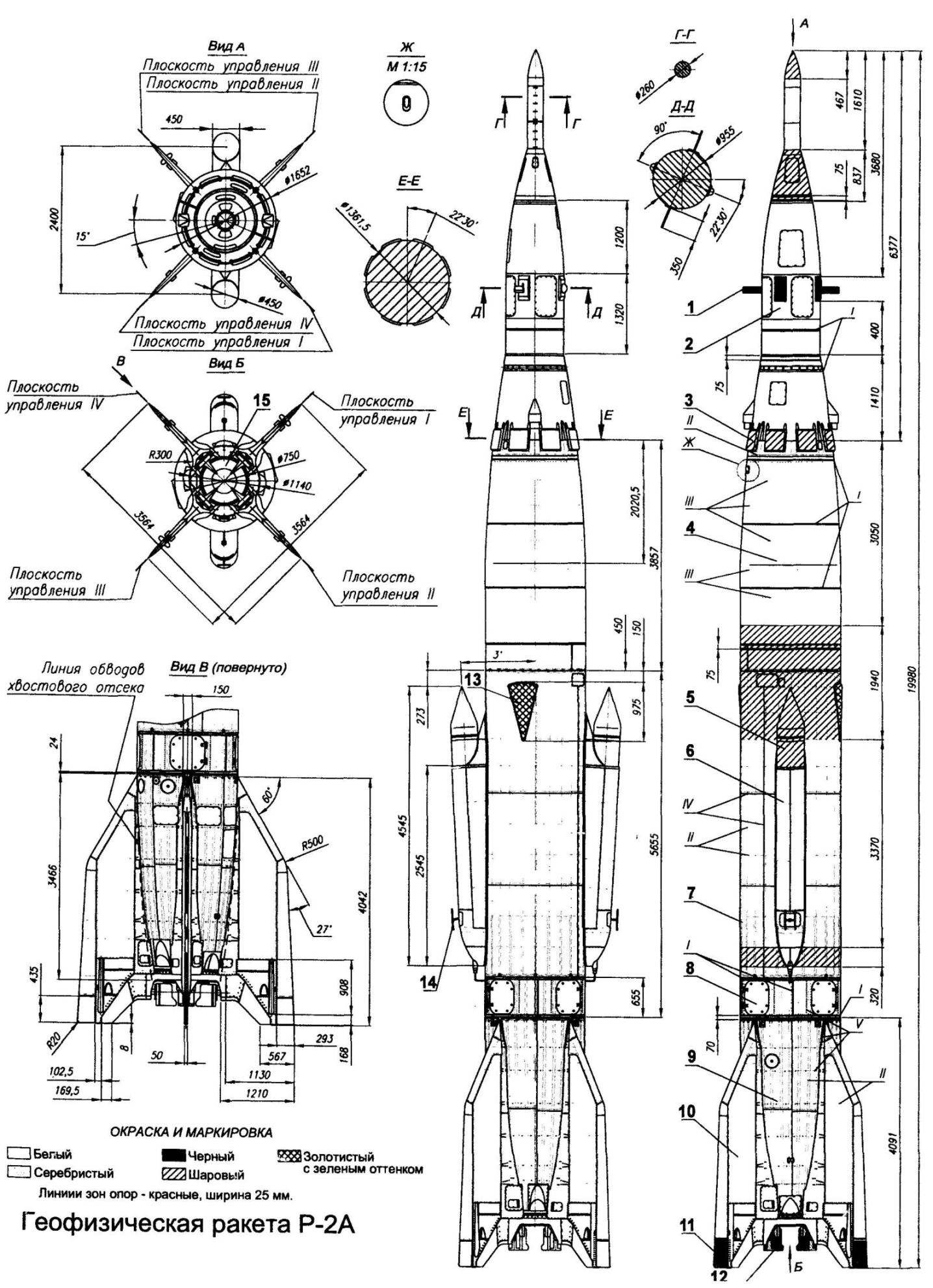
Geophysical rocket R-2A:
1,3—telemetry antenna head; 2—warhead; 4—fuel tank; 5—instrument container fire back; 6—side-housing; 7—fuel compartment; 8—instrument compartment; 9—the rear compartment; 10—console aerodynamic stabilizer; 11 —aerodynamic control surfaces; 12—gas rudders; 13—antenna of the frequency control; 14—telemetry antenna; 15—nozzle rocket engine RD-101. I —joints; II—riveted joints (rivet with countersunk head); III—spot welding; IV—overlap panels; V—, riveted joints (rivet round head)
Side containers significantly improved and performed in two variants—one with data transmission via telemetry system and at the other, with the measurements on the container. The side containers were placed in special mortars and fired a pneumatic pusher at a slight angle to the longitudinal axis of the rocket on the ascending branch of the trajectory at a height of 55-60 km, and Then they flew solo to heights of 200-210 km, then free fall up to 2 km and then descended by parachute.
The head part was a pressurized module intended for the study of survival and animal wastes that are not ejected and escaped with GCH. On the head part could be established models for aerodynamic testing or spectrograph for optical observations. On separate instances of geophysical rockets instead of containers strengthened smoke containers to determine the direction and wind speed at heights. Deceleration of the head portion to transonic speeds was provided by opening the brake flaps. Next, from the height of 4-5 km WARHEAD was inhibited by the consecutive input of three of the pilot chute and subsequent disclosure of the two main domes at a height of 1.6—2.6 km.
Total from 1957 to 1960 conducted 13 launches of geophysical rockets R-2A, of which 11 were successful. This story about the history BRD R-2 it would be possible to complete, but I want to highlight another little-known fact of the history and activities of S. P. Korolev.
In 1957 the government of the people’s Republic of China appealed to the leadership of our country with the request to assist in the development of rocket technology in China. Our government has decided to provide such assistance, and ordered OKB-1 and its chief designer to convey the fraternal Chinese people for two BRD R-2 with a full complement of ground equipment (and one of the missiles in the form of training-split layout). In addition, to send our specialists for training Chinese comrades, and to develop educational posters on missiles and ground equipment. More was to donate the license for the production of R-2 and units of ground equipment to them, and also to send to China a complete set of technical documentation required for their manufacture and testing. Finally, transfer components for assemblies and systems of the R-2, to prepare and transmit educational-methodical documentation in the R-1 and R-2, samples of components, assemblies, devices and components of systems as visual AIDS in lectures.
The head of our specialists and the chief designer in China was the lead designer of R-2 P. I. Mileshin. Just sent of 45 professionals. S. P. Korolev personally supervised the execution of the decision of the government to assist China in the development of rocket technology. The result of this work is the first launch of Chinese BRD R-2 on November 5, 1960 It was as if the report of the fraternal Soviet people to the anniversary of the October revolution.
The first strategic
Initially, in the formation of NII-88, the government entrusted him with the development of three themes. The first two ended with the adoption of the ballistic missiles (BRDG) R-1 and R-2. The third theme N-1 was set the task of creating a ballistic missile with a maximum range of 3,000 km. Preliminary design BRD R-3 was defended in November — December 1949, He suggested the development of a single-stage ballistic missile with a launch mass of 65 — 70 tons For it was planned to create an entirely new liquid propellant rocket engine (LPRE) RD-110, with a thrust of 120 — 140 t, working on liquid oxygen and kerosene. Also needed a new control system, as in the design of the rocket was supposed to use aerodynamic design without stabilizers carriers and tanks of both components of liquid fuels. Special research and design solutions required the task of thermal protection for the descending branch of the trajectory of the warhead. She had to enter the dense layers of the atmosphere at a speed of 3.5 — 4 km/s.
In the defense of the conceptual design was expressed about the need to create experimental rocket (designated R-IN) for testing new technical solutions for future R-3. The project is of such missiles were developed by 1950, an Experimental rocket was to have a launch weight of 23.4 tons, and the construction of about 4 t and the thrust of the engine 40 of the vehicle. The estimated range of 935 km fuel Components, ethanol and liquid oxygen. Beginning of flight tests was planned for October 1951
In April 1950, the government, considering the progress in the development of BRD, made the decision about formation of the special design Bureau No. 1 (OKB-1) on the establishment of long-range missiles. Its head and chief designer was appointed S. P. Korolev. In-depth study of the project R-the OKB-1 showed that on its basis you can develop and implement a project BRGD combat with a maximum range of 1200 km. This was the basis of S. P. Korolev in October 1951 to apply to the government with a proposal to create such a missile later index R-5. This proposal was accepted. The project BRD R-5 was completed by the end of October. For it was to be used rocket engine RD-103 is being developed under the leadership of V. P. Glushko and representing a further modification of rocket engine RD-102 for BRD R-2.
According to the draft R-5 was to have: detachable warhead weighing 1425 kg, both carrying the fuel tank and aerodynamic design without stabilizers. The starting mass of the rocket made 28,61 t, and design — 4,93 t to increase the range from 935 km from R-3A to 1200 km at the R-5 was required to enter the nozzles on the nozzle of the engine, which allowed to hope for a slight increase in specific impulse, and not sealed and therefore a heavy instrument compartment. Exception aerodynamic stabilizers significantly reduce the mass of the tail section and used in his construction aluminum alloys in contrast to the previous R-1 and R-2. Save valuable mass gave the use of both all-welded load-bearing fuel tanks with a rear-mounted tank of liquid oxygen.
To improve the reliability of the control system, which was developed under the leadership of chief designers N..Pilyugin and Kuznetsov were supposed to post the control devices and their sensing elements (gyroscopes and gyroscopic integrators). Themselves instruments of control were the instrument compartment, located just behind the tank of liquid oxygen and being one with him, and the sensing elements are mounted on special brackets in the inter-tank section compartment. This design allowed us to dramatically reduce the vibration from the engine, greatly affect the operation of gyroscopic instruments. The tanks design has made special varanaviciene system, which reduced nesebor the remains of the fuel components for 100 kg.
To solve tactical problems when shooting at an intermediate range to be fitted with the missile for more mounted combat units (2 or 4 pieces depending on range) up to a total weight 3830 kg. in addition, because of the large range was necessary to introduce the radio range. Development of a complex ground and launch equipment was assigned to the team, which was led by V. P. Barmin. The complex consisted of: technical position (where the rocket passed prelaunch training), fuel and starting equipment.
BRD P-5 consisted of the head part (representing a pointed cylinder), upper instrument compartment, fuel tank, magbabago compartment, oxidizer tank, tail section (located in it LPRE RD-103) and toroidal tank of hydrogen peroxide. On the body the tail section was located pylons with aerodynamic rudders, and in its end frame — start-up supports attached to them with gas rudders.
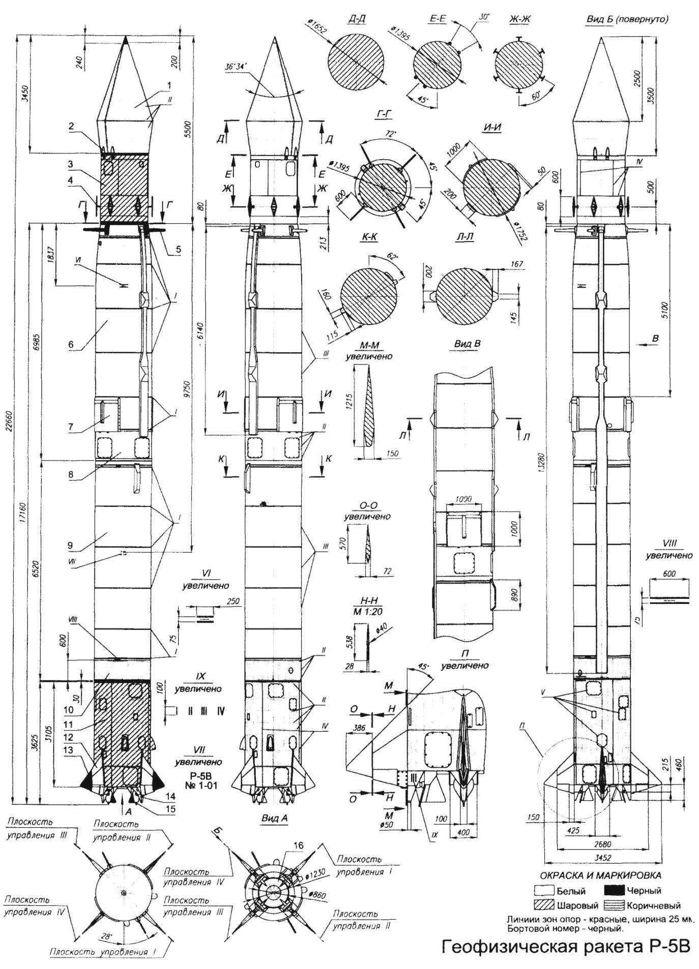
Geophysical rocket R-5V:
1 — fairing; 2 — joints of the head fairing; 3 — the case of the head of the scientific equipment; 4 — telemetry antenna head portion; 5 telemetry antenna; 6 — fuel tank; 7 — antenna control range; 8 — libacovea compartment; 9 — oxidizer tank; 10 — instrument compartment; 11 — the rear compartment; 12 — console of the stabilizer (the pole); 13 — aerodynamic handlebars; 14 — start-up support; 15 — gas drive; 16 — nozzle rocket engine RD-103 (colour — silver). I — joints; II — riveted joints (rivet with countersunk head); III — spot welding; IV — overlap panels; V — round head screws
The first phase of flight tests BRD R-5 was conducted at Kapustin Yar from 15 March to 23 may 1953 Just in this phase of testing was launched eight missiles. At start-up to a range of 1200 km, on 8 April, the accident occurred due to the destruction of the rockets in the loss of stability. The analysis showed that the cause was insufficiently reliable steering gears. In preparation for the second phase of flight testing in the design Department head of the rocket and control system was introduced a number of changes. The second phase of testing was conducted from October 30 to December 9, 1953 G. One of the seven rockets crashed due to damage to the cable network, which caused premature engine shutdown. In the third phase of testing, conducted from August 12, 1954 February 7, 1955, was carried out 19 launches, which identified the failures of the radio system range with the weakening of signals due to the influence of the jet engine. No additional work on the finalization of the missile was conducted as in December 1954 there have been three successful launches of rocket R-5M was designed according to the government resolution of April 10, 1954 G.
BRD R-5M was derived from rocket R-5 and was intended to deliver a nuclear warhead to a range of 1200 km. Work on it began in late 1953 it was Necessary to create a new head part, which would ensure the reduction of speed meetings with the ground twice. In the result, the head part took a conical shape, which resulted in a decrease in the length of the rocket and a significant change in its aerodynamic characteristics. And to use the gained experience in the training management system of the R-5, it was necessary to provide for the R-5M aerodynamic characteristics close to the characteristics of R-5. This condition is fulfilled by the installation of small stabilizers (pylons).
To ensure the reliability of the control system introduced the duplication of control circuits, said two independent channels of operation of the automatic stabilization, the number of steering machines was increased to six. Four of them worked for the gas rudders (one on each wheel), and the remaining two in his pair of aerodynamic rudders connected kinematically. This established work on each channel simultaneously stabilize all four wheels.
The new block layout of the devices of the control system gave the possibility to reduce the number of cables and connectors. Replacement power number of elements from onboard sources on the ground have greatly reduced the number of critical elements on Board and improve the reliability of the remaining. Also significantly simplified pneumatic-hydraulic circuit of the missile by entering the fully automatic start of the engine.
From 20 January to 9 July 1955, has held two subsequent test phase BRD R-5M, which launched 14 missiles. This has revealed a number of separate lekarstvennyh shortcomings. One of them was the fluctuations (flutter) of the air rudders, the solution of which changed the design of the rudder and increased the stiffness of the kinematics of the drive.
The final stage of flight tests took place from 9 August to 19 November 1955 was launched 10 missiles, eight of which task was accomplished. From 11 January to 6 February 1956 passed the scoring test of six products, one of which started 2 February, carried a real nuclear warhead. All the launches were successful and in June 1956 BRD R-5M with ground support equipment was put into service under the symbol 8К51 and put into series production. Earlier, in Soviet period in the open press it was known as “the first strategic missile”. In 1959, two regiments, armed with missiles R-5M was on combat duty in the Crimea and in Kaliningrad region. For this assignment the team of OKB-1 and the number of its employees received state awards, and the S. P. Korolev and his first Deputy V. P. Mishin was awarded the title of Hero of Socialist Labor.
On the basis of the R-5M has developed a new series of research rockets from R-5A to R-5ВАО. They reached a height of 482 km. the Missiles were designed to measure the air pressure at altitudes of 400 — 500 km of the study of micrometeorites, the ionosphere, the ultraviolet part of solar radiation, survival and animal wastes when lifting to a height of 500 km, a test of recovery system the head part. For the R-5A have developed a new head part. Unlike the previous it was equipped with the brake flaps to an initial deceleration and stabilization, with the result that the descent speed was about 2 km/s. launches of geophysical rockets R-5A and R-5B, which began in 1958, reached the height of 473 km.
In 1963 appeared subsequent modification of missiles — R-5V (- 5V). It was equipped with a new stable warhead for the study of solar ultraviolet radiation. These experiments were continued in 1963 with a high-altitude astrophysical Observatory (VAO). Spherical container station is located under the conical nose fairing, which is reset at the end of the active leg of the flight, and then separated the whole head part.
After braking in the dense layers of the atmosphere the container down on a parachute. These missiles had a single index — R-5ВАО.
In the 1970’s, the rocket was modified for use on the international space program of socialist countries — Interkosmos (“Vertical”), has created a new version of the R-5ВАО, better known as “Vertical-1”. For it has developed a new head part with a mass of 1300 kg, consisting of a cylindrical instrument compartment and a spherical reentry of the container. In the cylindrical compartment located instruments to measure the density of electrons and ions and temperature of electrons depending on the height of the photometer to measure ultraviolet and submillimeter component of the solar radiation.
In the spherical container were instruments for photographing the Sun in x-ray spectrum, x-ray spectrometer and instruments to study meteors.
“Vertical-1” was launched from the Kapustin Yar cosmodrome in November 1970, the Head part was separated after the end of the active phase and reached an altitude of 483 km and the payload was ejected streams of ions in the upper atmosphere. Ground tracking stations observed the emission and receiving telemetry data, measured radiomovlennya in the ionosphere. After the reduction to the height of 100 km spherical container was separated from the head part and is saved by parachute.
The carrier rocket Sputnik
24 Oct 1957 in human history, a momentous event occurred—the Earth’s orbit was launched the first artificial satellite. And it was done in our country! The launch took place at 22 hours 28 minutes Moscow time from the launch pad of the fifth test site of the Ministry of defense of the USSR, now known as the Baikonur cosmodrome. The whole world has heard the call sign of the first small spacecraft made by human hands. People all over the world could watch his flight. But in fact, they saw not the satellite, and the second stage booster that carried it into orbit. And she had a significant size—about 25 meters in length and weighing more than 7 tons.
It was the fourth test launch of an Intercontinental ballistic missile R-7, created in OKB-1 under the guidance of academician S. P. Korolev.
The first study of a ballistic missile with Intercontinental range was launched in 1947 in the framework of the project R-3. They were carried out on the instructions of S. P. Korolev research Institute-4 of Ministry of defense group headed by M. K. Tikhonravov. It was found that for Intercontinental ballistic missiles (ICBMs) are the most rational design scheme is a two-stage longitudinal division steps (scheme “package”). The main factors dictate in the circumstances of the choice of the constructive scheme, was the level of development of liquid rocket engines (LRE) and the possibility of transporting by rail. The scheme of the “package” is allowed to create ICBMs weighing 250-300 t on the basis of five missile units (Central and four side) with the same engine.
Further study of the “package” scheme were research themes of the NC and T1, made in OKB-1 in 1950 -1953. under T1 was developed a draft design of the missile with a flight range of 8000 km and a warhead weight of 3 t and a start—up to 170 t In October 1953 of the legislative bodies changed the design task—warhead weight (warhead) were identified in 5.5 t, while maintaining range. In this regard, required radical recycling of the conceptual design.
The government decree on the establishment of the ICBM R-7, received index 8К71 and designed to deliver a powerful warhead weighing 5.5 t at a distance of 8500 thousand kilometers, adopted in may 1954 And in July of that year was ready for its preliminary design. Leading designer ICBM R-7 was appointed D. I. Kozlov. Dimensions and weight of the warhead, as well as the specified range and then the possibility of engine determined the appearance and mass-dimensional characteristics of MBR. It was supposed to be a two-stage rocket “package” scheme, are equipped with a unified liquid rocket engines with a thrust of 800— 900 oC, using the new fuel a couple of “liquid oxygen—kerosene”. Such rocket engine was developed in OKB-486 under the leadership of V. P. Glushko. These motors are open circuit had four combustion chambers and turbopump supply system of fuel components, driven by a turbine that uses the vapor-gas generated in the gasifier with catalytic decomposition of hydrogen peroxide.
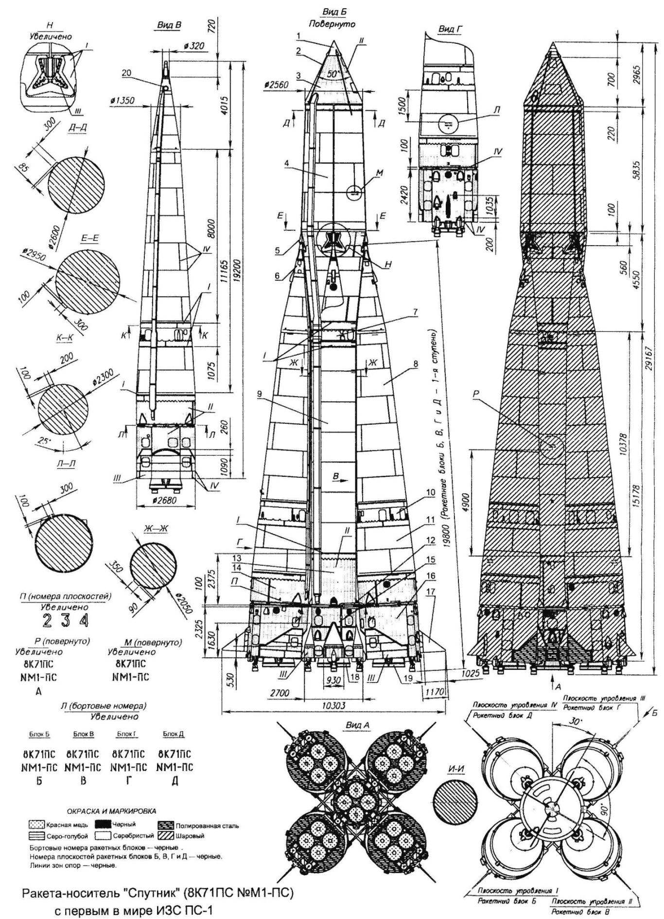
The carrier rocket Sputnik:
1 fairing SS-1; 2—antenna of the satellite; 3—fairing; 4—oxidizer tank of the unit A; 5—power bracket; 6—power cone; 7—milakovic Bay unit A; 8 — oxidizer tank of the side blocks; 9—fuel tank of unit A; 10—libacovea compartment side blocks; 11 — fuel tank side blocks; 12—rod ties; 13—compartment tanks of hydrogen peroxide and liquid nitrogen unit A; 14—compartment tanks of hydrogen peroxide and liquid nitrogen side blocks; 15 — the rear compartment of the unit is A; 16—rear compartment side blocks; 17—aerodynamic wheel; 18—RD-108; 19–the RD-107; 20—nozzle vent boost pressure from the oxidizer tank side blocks.
I—spot welding; II—riveted joint (rivet with countersunk head); III—riveted joint (rivet with a hemispherical head); IV—welding seam
To ensure the required reliability of abandoned hydraulic connections between the blocks. The approved scheme of separation of stages in flight practically does not require additional energy reserves. For these purposes boost the oxygen tanks of the side blocks. A repulsive force was created with the help of reactive jets flowing out of the built-in tanks are special nozzles that are triggered at the right time. Part of the separation process served and thrust aftereffect engines side blocks. The starting point of the separation process was a team off of these engines.
Control and stabilization of the missile was carried out steering a rocket engine, developed in OKB-1 led by M. V. Melnikov and included in the design of the main engines. In the initial phase of flight was used and aerodynamic control surfaces mounted on the pylons of the side rocket units. Machines and control devices were developed under the leadership of chief designers N..Pilyugin and Kuznetsov.
Preliminary design included the launch using a launch pad. However, in this case you would need to build a wind-shelter wall height of not less than 2/3 of the length of the rocket, having a high “windage”. In December 1954, decided to abandon this beginning. There was the option of suspension of the missile in a special starting system, excluding wind protection with minimal starting loads. The need for special facilities was due to the fact that in flight the Central unit before the division was hanging in the side blocks due to their greater thrust-weight ratio. Therefore, on the launch facility, the rocket was suspended for these side blocks. The launch complex and the technical position was created under the leadership of chief designer V. P. Barmin.
A special place in the preparations for testing the R-7 took the question of choice of area for construction of the landfill. The special Commission considered several options for the placement of a polygon and opted for the desert is 35 km from the Tyuratam station South-Eastern railway, linking Central areas of the country and the Central Asian republics. In may 1955, the first military construction units arrived at the scene and began to prepare the site for construction of the launch complex and technical positions. It was the beginning of the Baikonur cosmodrome. For a residential area chose a site on the shore of the Syrdarya river a few kilometers from the station.
The design of the ICBM R-7
The package is formed by a Central block (rocket block) with rocket engine RD-108 with four steering engine (total thrust at the ground 812 kN) and arranged around it on the planes of stabilization, four identical conical lateral blocks (rocket pods B, C, D and e) with rocket engine RD-107 (with a total thrust of 821 kN), each of which had two steering chambers of combustion. In flight, the blocks rested its front spherical bearings on special brackets placed on the power frame of the tank oxidizer Central unit. The design of the brackets is provided only transfer longitudinal loads from the side of the blocks and prevented the free exit of their front legs with the disappearance of the longitudinal force when turning off the engines. To transfer tangential loads served break the tie located at the bottom of the power zone, pivotally mounted on the side blocks.
The Central unit consisted of (bottom to top) of the tail section 15, which was installed rocket engine RD-108, compartment tanks of hydrogen peroxide, 13 (it was a toroidal tank of liquid nitrogen), a cylindrical tank 9, magbabago compartment 7, compartment of an oxidizer tank 4 and the instrument.
Tail section riveted construction was made in form of cylindrical shell, reinforced from the inside power set (stringers and frames). It made some hatches for access to engine and instrumentation. At the bottom of the compartment to control surfaces were located fairings to accommodate the steering chambers of RD-108, the Pro-forming of the compartment. The engine was mounted on front end frame with tubular frame. On the front bulkhead were the security ring with four brackets mounted on the control surfaces. They have served to embed pnevmatikos, joined by tie rod 12, the lower connections between the blocks. The screed is connected to the hinge locks and therefore does not interfere with the lateral movement of the block relative to the Central plane tangent to the generatrix of the housing of the Central unit.
To the front end bulkhead of the tail section is attached to a tank of hydrogen peroxide, also made in the form of backed up by power set of a cylindrical shell with front and rear “skirts”. Inside the compartment has passed the pipelines of the oxidizer and fuel. To the frame of the front “skirt” of the compartment attaches all-welded cylindrical fuel tank placed inside the elements of pneumatic and hydraulic circuits and pipe tunnel, through which passed supplies the pipeline oxidant. Tank of fuel through libacovea compartment riveted construction, which housed some of the elements of automation and appliances control system, connected with all-welded tank of oxidizer. To access the devices in inter-tank section compartment there were hatches.
Oxidizer tank was formed by two shells in the form of truncated cones, facing large grounds to each other. Shell connected powerful power frame. To it spot welded was welded to four power bracket 5 complex shapes with fixed ball bearings. They included ball end walls of the power cones side blocks. Each tip had a cylindrical bore the axis of which is perpendicular to the axis of the rocket, in relation to the generatrix of the oxidizer tank. In the recess was a part of the cylindrical finger tip ball side block, preventing its turning with respect to the Central plane tangent to the generatrix of the conical shell of the tank oxidizer Central unit and lateral rotation of the unit around its longitudinal axis, but allow rotation in the plane stabilization, corresponding to the side of the block.
On the front end of the oxidizer tank was located conical instrument compartment riveted construction. Inside it on a special frame mounted devices of the control system, the control units and other equipment. To access them in the skin compartment were several large hatches. On the front bulkhead of the compartment were mounted the fittings which were attached three explosive bolts for connection to a payload. Pipelines charge cables on-Board power supply was held outside and closed the fairing. The design weight Central unit with the engine was 6000 kg.

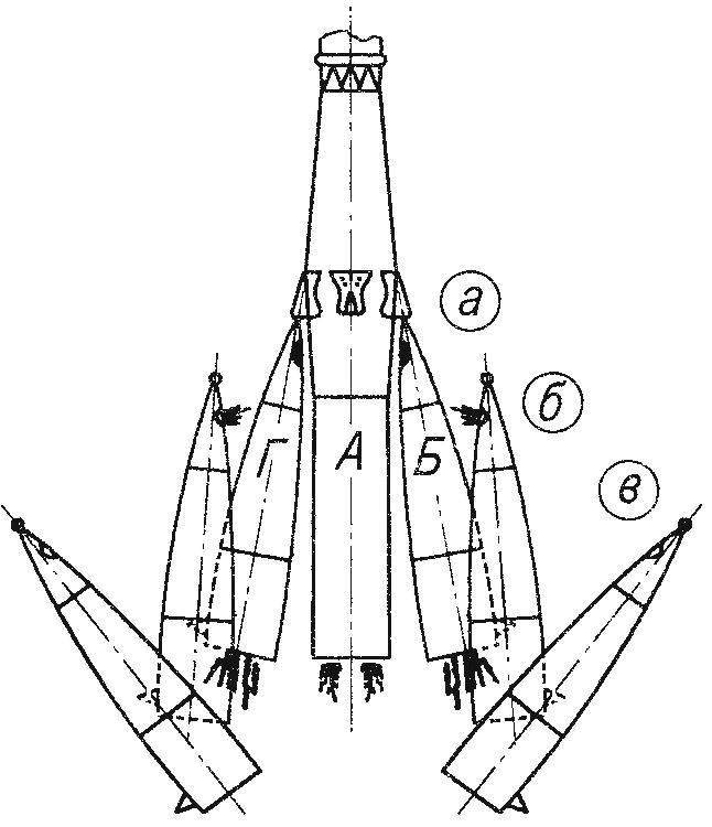
The sequence of separation of the side blocks of the R-7 rocket:
and the disclosure package under the action of thrust of the main engines; b—opening nozzles positioned on the inner side force of the cone; the withdrawal of the side units to the sides
Design of unit side consisted of a force of the cone 6, the oxidizer tank 8, magbabago compartment 10, tank 11, tank compartment, hydrogen peroxide and liquid nitrogen 14, and a cylindrical tail section 16. Oxidizer tank is a welded structure had at the top the bottom of the hatch to reset the internal charge pressure through a special nozzle 20 in the separation of the side blocks. Libacovea compartment was made in the form of a conical, reinforced with longitudinal (stringers) and transverse (two frames) the power set of the shell. It housed some of the instruments and control elements providing the control side unit during the period of the joint operation as part of the launch. To access the devices in the compartment there were hatches closed lids.
Fuel tank is all-welded, extending inside the pipe tunnel, through which the pipeline is laid oxidant. Inside the tanks of fuel and oxidizer were elements of pneumatic and hydraulic circuits. To the rear of the tank were joined by a short Bay, within which was suspended a toroidal tanks of hydrogen peroxide and liquid nitrogen. Compartment was made in the form of a shell reinforced with longitudinal and transverse power set. To his end the frame attaches the cylindrical tail section, the body of which has also been riveted construction shell, reinforced power set. In the tail section housed a rocket engine mounted on the frame. On the lateral surface mounted single aerodynamic wheel 17 and a pylon for the drive which used electric steering apparatus. The rear end and part of side compartment surface facing to the Central unit, were covered with heat-reflecting screen from sheets of asbestos and polished steel. To access the engine and control mechanisms in the body compartments were made hatches closed lids. Pipelines charge cables on-Board power supply was held outside and closed the fairing. A lot of the design side of the unit with the engine was 3750 kg.
As structural materials for manufacturing the main elements of the R-7 rocket was used welded aluminum alloys and power of the cone side of the block—titanium alloys.
The process of separating the side blocks were as follows: their boosters were transferred to the low-thrust mode, and the control engines shut down. Pnevmatiki freed of the ties, and the “package” was opened from below under the action of the traction engines. Spherical stops are rotated in and out of engagement with the brackets on the Central block, which went forward. At this point closed limit switches. Their team off the engine side of the blocks and opened the nozzle, located on the inner side of the power cone through which vented the boost pressure of the oxidizer tank. The reaction force is bred top side of the blocks, taking them from a Central to a safe distance.
The R-7 rocket and its modifications were fixed on the launch facility (as mentioned above) in limbo. Cross-section, in which the binding, lies in the plane of the power bulkhead of the oxidizer tank. For the suspension in the force cones of the side units had a special “pockets” with reference planes. They included the brackets of the four security pillars of the starting structure. When starting the engine, the load on the brackets with the growth of the engine thrust is decreased, and when the load is removed power support, spinning under the action of the counterweights came out of “pockets” and deviated to the side, allowing the missile to leave the launch facilities.
Test of an ICBM R-7 began in may 1957, According to visual observations, the first flight took place normally to 60, and then the tail section emerged the flames. Analysis of telemetry information showed that the fire started before the separation of the rocket. This led to premature engine shutdown emergency unit and disruption of normal flight.
In August 1957 the first “regular” flight of the R-7, which was the official message. Despite the fact that, according to the reports, he was normal, the head part when entering the dense layers of the atmosphere was destroyed. Subsequent launches of 1957 passed without incident.
In September 1955, the S. P. Korolev turned to the government with a proposal to launch a simple satellite of the Earth using the rocket R-7 in the framework of the International geophysical year. This proposal was accepted. At OKB-1 created a special Department for the development of the spacecraft, which was headed by M. K. Tikhonravov, who joined with a group of employees from NII-4. They designed a satellite weighing 1.5 tons, which was intended to equip scientific equipment developed in the institutes of the Academy of Sciences. However, the target time this instrument was not ready, and the engines of the R-7 did not develop the installed specific thrust. So Sergei Korolev for the conquest of the priority suggested in the shortest possible time to produce and launch the simplest satellite (PS). In February 1957 the government adopted corresponding resolution.
The first artificial Earth satellite (AES)
It was a polished aluminum sphere with a diameter of 580 mm and weight 83,6 kg, equipped with a transmitter and four whip antennas, with a length of one pair of 2.4 m and the other is 3.9 m. the Antenna was mounted on spring loaded brackets, distributing them at an angle of 35 degrees from the longitudinal axis. Sphere was formed by two paleobiologii 2 mm thick, with docking frames, fastened by bolts 36. Inside the satellite were mounted: a transmitter, a power supply with three batteries, remote switch, and fan dual relay control systems, control thermostats and barrele. After assembling the satellite was filled with dry nitrogen to a pressure of 1.3 ATM. The inclusion of the radio transmitter and the temperature control system was made remote switch, triggered by heel contact at the moment of separation of the satellite from the carrier.
The transmitter periodically emits a signal duration of 0.4 second alternately, in two waves with a length of 7 m and 15 m. When the temperature in the satellite is above +50°C or below 0°C and when the pressure inside is below 0,35 ATM was supposed to be thermal or Barrela, therefore changing the duration of periodic signals emitted by a radio transmitter. The temperature in the satellite to the extent necessary provided the fan starts when the temperature rises above 30°C and off when the reduction of 20-23°C. the Fan ran dual thermostats. Lead designer of the object SS was M. S. Khomyakov.
For the launch of the satellite used a modified ICBM R-7 (product 8К71ПС). With the missiles off the front of the instrument compartment and warhead, and instead mounted a conical fairing riveted construction, the top frame which is cemented PS-1 (the simplest satellite 1), which was destined to go down in history. At the top it is closed by a small, conical Radome, in which the passages for the antenna. Fairing it was dropped by the team before the separation of the satellite. PS he was separated from PH pneumatocoeles.
Start PH 8К71ПС number M1-PS was held on October 4, 1957 the Second stage of the rocket satellite went into orbit with a perigee of 228 km and an apogee of 947 km and the time of one revolution around the Earth at 96.2 minutes, the satellite separated from the PH at 315 seconds after launch. The satellite was in orbit until 4 January 1958, having made 1440 turns. The Central block of the rocket made 882 revolution around the Earth and entered the dense layers of the atmosphere 2 Dec 1957
On 3 November 1957 was launched PH 8К71ПС No. M1-2ПС, which put into orbit the second satellite, which became the world’s first spacecraft. On Board were a living creature—the dog Laika.
Technical data BRD R-1:
total length………………………………..14,275 m
case diameter ………………………….1,652 m
the scope of the stabilizer…………………..3,654 m
starting weight…………………………..13 430 kg
lots of designs………………………..4030 kg
warhead weight………………………1075 kg
thrust LRE (earth)……………………….272 kN
the maximum range…..270 km
Technical data of the R-1E:
length…………………………………………………………..17,955 m
case diameter…………………………………………..1,652 m
the maximum transverse dimension of the housing…..2,59 m
the range of stabilizers…………………………………3,564 m
the length of the head portion……………………………………4,83 m
starting weight……………………………………………14,211 t
the thrust of the engine………………………………………………272 kN
the engine run time…………..70 with
maximum altitude………………………..100km
Sequence diagram of the missile R-1E:
start………………………………………………………………………………………………………………………………………..0 with
shooting a pair of side containers (velocity 800 m/s, height 67 km), time………………………………103 with
Department head of the — (velocity 35 m/s, altitude 95 km), the time………………………………………….188 with
the apogee (altitude 100 km), vrama…………………………………………………………………………………………………..195 with
entering the recovery system of the rocket body (altitude 90 km), the time from apogee…………………………………….45 with
the shooting of the 1st container from GC…………………………………………………………………………………………………..the altitude of 90 km
the shooting of the 2nd container GC…………………………………………………………………………………………………..the altitude of 42 km
the disclosure of the parachutes to MS and kill the containers (altitude 5 km), time from start…..400
the landing corps rakety…………………………………………………………………………………………………….40 min
Technical data BRD R-2:
length……………………………………………..17 650 mm
case diameter……………………………..1652 mm
the tail swing……………………………..3564 mm
maximum firing range….576 km
missile launch weight…………………..20 300 kg
the weight of the warhead………………………1500 kg
the mass of the rocket design……………….4460 kg
thrust rocket engine (on the ground)………………………..370 kN
specific impulse (on the ground)…………..2100 N. s/kg
Technical data R-2A:
length………………………………………………….19,98 m
case diameter………………………………….1,652 m
the range of stabilizers………………………..3,564 m
the length of the head portion…………………………..6,377 m
starting weight…………………………………..20 685 t
the thrust of the engine……………………………………..370 kN
the engine run time….100
maximum altitude……………….200 km
Sequence diagram of the missile R-2A:
start………………………………………………………………………………………………………………………………………0 with
shooting a pair of side containers (velocity 800 m/s, height 67 km)……………………………………….103 with
Department head of the (velocity 35 m/s, height of 195 km)……………………………………………………..188 with
the disclosure of the parachutes to MS and kill the containers (altitude 5 km) — time from start….400
Technical data BRD R-5:
starting weight………………………………..28 570 kg
the weight of the structure…………………………….4200 kg
warhead weight…………………………..1425 kg
the mass of the suspended warhead……………………………to 3830 kg
thrust rocket engine (on the ground level)………………43 TS
length……………………………………………….22115 mm
case diameter……………………………….1652 mm
the scope for aerodynamic rudders….2640 mm
Technical data BRD R-5M:
starting weight………………………………..28 680 kg
the weight of the structure……………………………..4390 kg
flight time………………………………….637 with
the height of the peak of the trajectory………………….304 km
maximum speed……………………..3016 m/s
thrust rocket engine (on the ground level)……………….43 860 kg
the duration of the work………………..115,4 with
specific thrust…………………………………….219,3 kg. s/kg
length………………………………………………..20 747 mm
case diameter……………………………….1652 mm
the scope for aerodynamic rudders….3452 mm
Technical specifications R-5A:
length…………………………………….23740 mm
case diameter……………………1652 mm
the range of stabilizers………….3452 mm
the length of the head portion…………….6367 mm
starting weight…………………….29 314 kg
the thrust of the engine……………………….438,6 kN
maximum altitude 482 km…
Technical data P-5V:
length…………………………………………………22660 mm
case diameter…………………………………1652 mm
the range of stabilizers……………………….3452 mm
the length of the head portion………………………….5500 mm
starting weight………………………………….29 500 kg
the thrust of the engine…………………………………….438,6 kN
the engine run time…100
maximum altitude………………485 km
Technical data PH Sputnik
Starting weight………………………………………………………………………………267 t
The weight of the structure……………………………………………………………………………22 t
Common dline……………………………………………………………………………………29,167 m
The scope for aerodynamic rudders…………………………………………………10,3 m
Side blocks (1st degree) length (hull)………………………………..19,2 m
the maximum diameter…………………………………………………………………….2,68 m
the thrust of the main engine earth……………………………………………………821 kN
The Central unit (2 tier) length (without payload Bay)….26,2 m
the maximum diameter…………………………………………………………………….2,95 m
mass of payload………………………………………………………………………to 1327 kg
the total thrust of the engines of the Earth………………………………………………….3980 kN
Sequence diagram of the start PH Sputnik
Lift-off……………………………….0 min 00,0 from
The separation of the 1st stage……………………..1 min 56,38 with
shutdown control of the Central unit….4 min 54.6 from
the separation of the object PS-1…………………..6 min 14,5 with
Advice to the Modeler
Research rocket R-1E may serve as a model for modeling a class of models for realism of flight for a fairly experienced young rocketmodeler. If you use the motor МРД10-8-4 the most suitable to be scale 1:25. Complex aerodynamic shapes allow to hope for a high enough score bench evaluation. The model can demonstrate in-flight special effects — separation of the head portion, the ejection side of the container and the descent of the rocket body on the four-domed system of salvation. It will also allow you to obtain a high grade flight. For sustainability-models in flight, it is necessary that the position of its center of mass was at a minimum distance of 443 mm from the nozzle head part, if the model is made in scale 1:25.
Research rocket R-2A can serve as a model for modeling a class of models for realism of flight for a fairly experienced young rocketmodeler. If you use the motor MRD 10-8-4 most suitable to be scale 1:25. Complex aerodynamic shapes allow to hope for a high enough score bench evaluation. The model can demonstrate in-flight special effects—separation of the head portion, the ejection side of the container and the salvation of the missile body. It will also allow you to obtain a high grade flight.
To ensure steady flight-models it is necessary that the position of its center of mass was at a minimum distance of 527 mm from the nozzle head part, if the model is made in scale 1:25.
Geophysical rocket R-5V has long been popular with the young rocketmodeler. It has long been demonstrated in the exposition of the pavilion “Space” at ENEA USSR. Such models are copies, made in scale 1:25 the prototype repeatedly and successfully presented at competitions rocketmodeler of the suburban town of Elektrostal. Scale 1:25 for the simulation is the best. It results in a large model, which can be repeated all the details of the prototype and if you use the motor MRD 20-6-4 to visually attractive flight.
Such a model in flight can execute the following special effects as the prototype — reset both halves of payload fairing separation and the layout of the payload, i.e. the model will be split up in flight into four parts, each of which are saved on your parachute. To ensure steady flight-models requires that the position of the center of mass of the fully loaded model was at a distance of 525 mm from the nose fairing. This is ensured by centering weight, which are best placed in the layout of the payload.
To simplify pre-flight preparation, we recommend the following technological partitioning of the model: the two halves of the fairing, the layout of the payload, chassis, aerodynamic and gas rudders.
If you want to build a flying model, for the Central and side blocks I recommend to use constructive solutions described in the magazine “M-K” No. 11,2002, and No. 5, 2003, on the model of copy of the carrier rocket “Soyuz-U2”.
Literature
1. Gatland K. W. the Development of rockets. — M.: Foreign literature, 1956.
2. Rocket and space Corporation “Energia”.With.P.Queen. Under the editorship of Yu. p. Semenov. 1996
3. S. P. Korolev and his cause. Light and shadow in the history of space exploration. Under the editorship of academician B. V. Rauschenbach. — M.: Nauka, 1998
V. MINAKOV, engineer
Recommend to read
 THE WATER IS HEATED THE SMOKE
Having a stove ( coal or wood), it is possible to provide hot water sink in the kitchen and even the shower using the heater device, allowing the use of the heat of the hot gases that... THE LACES FROM THE HATS…
Sometimes it is difficult for the elderly person to tie a shoelace. To help out maybe round hat elastic, forever laced and tied. After this improvement, the boots are easy to put on with...
