“SUPER SABRE” OVERCOMES “THE SOUND”

Supersonic aircraft F100D Super Sabre. During the Korean war, which lasted from 1950 to 1953, in service with the us strike aircraft consisted of jet planes F-86 “saber” (“Sabre”) and the F-94 (“Starfire”) with transonic speeds. These machines served in first line until the mid 1950-ies, when they began to be replaced by new, this time a supersonic aircraft. New generation cars to be called Centuty fighters (fighters of the century) or “acres”, according to their numerical index. First among these has been the aircraft of the company “North American”, which received the designation F-100 “Super sabre”.

The company “North American”, which had enough experience in the production and fine-tuning the best at the time of the American F-86 sabre, began design work on the new aircraft in February 1949.
 
The F-100 was a logical continuation of the F-86 and initially was called the same as the predecessor — “sabre” index 45 (which meant that the sweep angle of the wing). In the first phase the company has worked on own funds — without having order. In January 1951 the situation changed for the better — “North American” received from the military Department an order for two prototypes and 110 production vehicles with the designation F-100A “Super sabre”, and work on the prototype started to move faster. In September of the same year the results of its pre-project handed over to representatives of the air force.
 
Finishing “Super Sabre”, however, was not simple, as evidenced by the differences of the leading experts of the project of Raymond rice and ed Schmid regarding aerodynamic solutions that eventually led to the departure of Schmid company in August 1952.
54 months of hard work of designers and manufacturers — and by 24 April 1953, the first prototype YF-100A was completed and transported with the aircraft plant in Los Angeles, on a test basis Edwards. And already on may 25 in the cockpit sat the chief pilot of the company “North American” George Welsh for the first time lifted the car into the air.
 
At that time, the developers of the new jets paid great attention to the advertising record flight to establish world records. A lot of attention to such advertising aircraft of its own paid and the company “North American”. One of those flights on the first prototype YF-100A for setting the world record made on 29 October 1953 test pilot Colonel Frank Everest. Pyatnadtsatikilometrovaya distance at an altitude of about 100 m, the pilot flew twice. The average flight speed reaching 1215,287 km/h, which corresponds to the number M= 1,09, which was a new world speed record. The height of the span over the dimensional database according to the rules of the FAI was supposed to be about 100 m, and the speed record is counted only if it exceeds the old by more than one percent.
 
F-100C
 
F-100D USAF
 
F-100D USAF
 
Those days for “North American” memorable for another reason — George Welch took off in one of the three first production F-100A, which later, in November 1953, included in the 479-th wing, stationed at George air force base.
 
The testing of the prototypes and the first production cars revealed some shortcomings of the aircraft; the main of them was a small margin of directional stability. Despite the objections of test pilots, the supply of production vehicles to the customer continued. Shortcomings of the aircraft ultimately led to disaster — the car that was piloted by George Welch, went into a dive and collapsed in the air, pilot died. This disaster was followed by two more, and then, in November 1954, the flights of the first series was banned. Subsequently, they have strengthened and enlarged tailplane and increased the wingspan.
The subsequent series of machines developed in the process of production.
 
The U.S. air force received 203 machine version of the F-100A (fighter variant) with armament of four 20-mm guns M-39F Aircraft equipped with turbojet engine “Pratt & Whitney” L57-R-7 6000 kgf thrust in afterburner, and starting with the 168th released machine — more powerful turbojet J57-P-39. Serial production of this version ended in April 1955. In combat units, they gained popularity, and soon they were replaced by F-100S.
 
Fighter-bomber F-100D Super Sabre
 
Fighter-bomber F-100D Super Sabre
 
Fighter-bomber F-100D Super Sabre:
 
1 —rod receivers of air pressure; 2—fold intake of the auxiliary turbine; 3—cone system emergency discharge of fuel; 4—fold hatches that covered the straps of the braking parachute; 5—compartment brake parachute; 6—fold niches main landing gear; 7—brake flap; 8—fold niche of the front landing gear; 9—ports of guns; 10—receiver system in-flight refueling; 11—a beam holders hanging weapons or fuel tanks; 12—flap

 
The new aircraft was a conceptual fighter-bomber, which is confirmed by its operation, which showed that the aircraft is not only the classic fighter, and with minor modifications can be used to support ground troops.
 
For this F-100C, representing the fuselage of the production F-100A, connected with the new enhanced wing, equipped with a suspension system for bomb armament with a maximum load of 3178 kg This hybrid first took to the skies in July 1954.
 
The first production fighter-bomber F-100S flew on 17 January 1955. Subsequently, it was released 476 of these machines.
 
The race for the world record was not spared and the new aircraft version. On it 20 Aug 1955, Colonel Horace A. Hanes set a new world speed record 1323,31 km/h (M = 1,24) on the altitude of 12 000 m.
 
In late 1955 instead of F-100S began to produce the F-100D. The car finished the wing between the ailerons and fuselage mounted flaps that were not present in previous versions. The payload brought to 3405 kg and updated instrumentation.
 
The first instance of the F-100D flew in January 1956. Total built 1274 of the machine.
 
The last production aircraft version of the “D” had the attachment points of the rocket boosters maximum thrust of about 58 cu, which was used for take-off without a run — for example, from the launch pads of specially equipped vehicles or fallout shelters.
 
Fig. 2. Ejection seat pilot
 
Fig. 2. Ejection seat of the pilot:
 
1—guide rail; 2 — visor head protection; 3—a headrest; 4—the back of the chair; 5—belt harness system; 6—the handle to bring the catapult in action; 7—step; 8—Cup for stowing the parachute

 
Fig. 3. The cockpit
 
Fig. 3. Cockpit:
 
1—left instrument panel; 2—arm tilt canopy; 3—bulletproof glass; 4—sight; 5—Central dashboard; 6—pedals control rudder; 7—right instrument panel

 
The next and last production option — double F-100F, converted from a single F-100D by lengthening the fuselage by 0.9 m to install a second chair. Machine, armed with paired cannon, had decreased to 2719 kg payload. The first prototype Sparky took off on August 3, 1956, and the first production machine — March 7, 1957. It was built 339 aircraft F-100F, considered as combat units along with single.
 
Series production aircraft “Super sabre” ceased in 1959. In subsequent years, the remaining machines have undergone several improvements. For example, they replaced sash auxiliary air turbine more reliable, borrowed from the aircraft the F-102 “Delta Dagger” and changed the shape of toplivoprovode rod with a straight to curved.
 
The U.S. air force used “Super sabre” and in combat in Vietnam, where they were pushed mostly “Phantom II”. In 1967 they transferred to the aviation of the national guard, and then in 1980 he retired.
Europe’s “Super Sabres” were exploited by the French air force until 1976, after which he was transferred to Denmark and Turkey, where they served until the 1980s.
 
In 1960, 80 aircraft version “And” altered version “D” and transferred to the Taiwan air force.
 
A few cars F-100F converted in towing aerial targets, giving them the designation DF-100F, and 81 “Super sabre” overage — unmanned aerial target designation ° F-100.
 
Design description
 
The aircraft was a supersonic single-engine single-engine airplane had all-metal construction with swept wing and tail.
 
The fuselage is semi-monocoque consisted of two parts, joined at the rear edge of the wing for ease of replacement of the engine. In the front was the air channel of oval cross section, which was held under electrical and radio compartments and the cockpit, then the channel cross section smoothly into the round inlet to the engine.
 
The pilot was housed in the ejection seat, which provided a safe evacuation of the aircraft at all speeds up to supersonic. Air brake served located in the lower part of the fuselage is a flap that could be deflected at an angle of 50 degrees. At the top of the fuselage behind the cockpit was the auxiliary air turbine generator — in case of failure of the engine it was developed for on-Board electricity consumers.
 
Behind, on the left side of the fuselage was located 17 hatches that covered the straps of the braking parachute, which was placed in the compartment between the stabilizer and the fuselage. In the front part of the fuselage under the engine intake was installed rod air receiver pressure; the Parking lot is “lance” “broken” and worked my way up.
 
The all-metal wing with a sweep angle of 45° to the front edge had a profile with a relative thickness of 7%. Wing consisted of 36 main parts, which together with two spars and stringers formed caisson compartment. The wing was equipped with automatic slats. In the rear of the wing between the ailerons and fuselage were located flaps with a system of blowing boundary layer.
 
The tailplane had a similar wing design. The stabilizer was all-moving, otklonivshesj at an angle of 20°. Above the rudder on both sides of the keel were fairing system emergency discharge of fuel. Drive rudders — hydraulic, with automatic damping.
 
The main landing gear with wheels dimensions 856×224 mm, equipped with anti-skid devices were cleaned by means of a hydraulic system to the fuselage. There was hiding and a-pillar with dual wheels dimensions mm. 446×139 main landing gear upon their release, closed doors to prevent the ingress of dirt. The sash could be opened manually on the ground for maintenance.
 
F-100D with external fuel tanks
 
F-100D with external fuel tanks
 
F-100D of the air force of Denmark
 
F-100D of the air force of Denmark
 
F-100D of the French air force, painted in the colors of the 48th tactical fighter wing of the US and installed in the Park of the American airbase, Lacanha (England)
 
F-100D of the French air force, painted in the colors of the 48th tactical fighter wing of the US and installed in the Park of the American airbase, Lacanha (England)
 
F-100D at regular work
 
F-100D on routine work
 
The cockpit of an F-100D-55
 
The cockpit of the F-100D-55
 
The basis of the power plant of the aircraft is twin-shaft turbojet engine “Pratt & Whitney” maximum thrust 5310 kgs, equipped with an afterburner. Afterburner thrust is achieved 7700 kgs. Fuel tanks total capacity 6582 l housed in the fuselage and wing. If necessary, under the wing of suspended fuel tanks, and could be refueled in flight by the receiver located on the right wing.
 
Built-in armament consisted of four 20-mm guns M-39E with ammunition, 200 rounds per gun, housed in a front lower part of the fuselage guns was Rate of fire of 1500 rounds per minute.
 
Various combinations of missiles and bombs total weight up to 3405 kg is suspended under the wing.
 
Color plane produced in different versions — depending on time and location. Machine the U.S. air force was mostly silver with black letters and signs on the left half of the wing from the top, right — bottom, and on both sides of the fuselage. Many of them attended the colored supplements and signs of aviation parts.
 
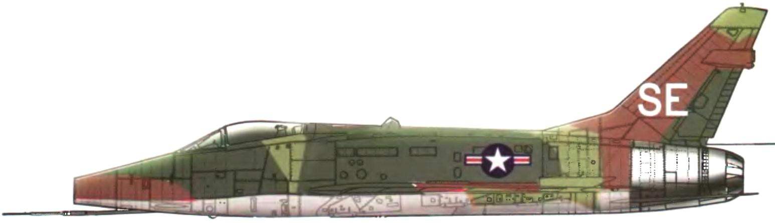
Planes some parts had top tri-color camo, in the form of spots of irregular shape, dark green, light green and brown. The lower surface is light gray. Similarly painted and machine French and Turkish air force. Planes Denmark are not painted either entirely covered with silver paint. They were later kamuflirovannaya paints a muddy brown and green colors on all surfaces.

Recommend to read

  • THE TAPE — SEWING MACHINETHE TAPE — SEWING MACHINE
    Usually a polyethylene film for greenhouses connected by heating with a soldering iron or the edge of the iron. While we don't always get a strong and reliable connection, especially...
  • TABLE GARDENERTABLE GARDENER
    Most of the work in the garden tedious due to the fact that one has to bend down. Create some "comfort" will help mobile stool, consisting of small plates and axle with wheels (you can...