A well still has no less significance today than before, especially given the popularity of dacha and cottage construction. No tap water, even passed through modern filters, can compare to well water.
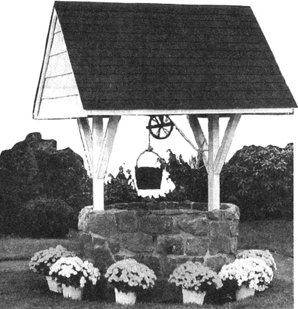
Given its usefulness, a well deserves that its visible part not only performs protective functions but also serves as decoration, as a decorative element of the site’s design. For those who have their own well, we recommend that when equipping its above-ground part, you don’t limit yourself to a simple canopy with a lid, but finish the canopy, for example, as shown in the photo. The roof superstructure shown here will suit both an active well and can simply serve as its imitation, a beautiful detail of a recreation area, if you don’t have the opportunity to dig a well.
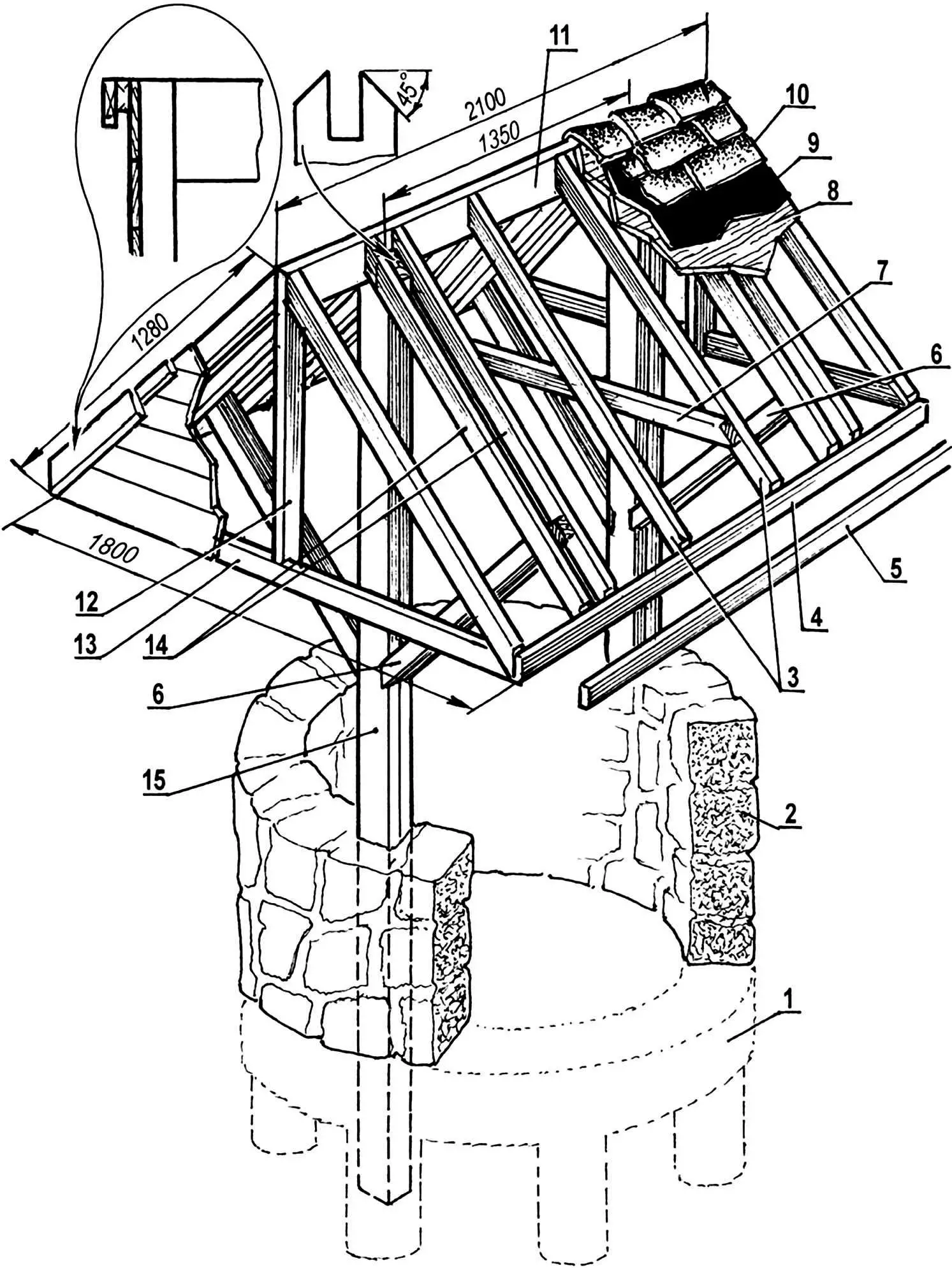
1 — foundation; 2 — base masonry; 3 — rafters; 4 — rafter binding; 5 — overlay strip-clamp for roofing felt; 6 — struts-spacers; 7 — rafter tie; 8 — rafter sheathing; 9 — roofing felt; 10 — tiles; 11 — ridge board; 12 — end post; 13 — end rafter tie; 14 — doubled rafters under strut-spacer; 15 — columnar support-base
The proposed roof superstructure variant is called a “Danish well” by specialists. Its base is a ring of large unhewn stones bonded with cement mortar. Its inner diameter is 1.2 m, and the outer diameter is 1.5 m. Such massive stone masonry requires a solid foundation. This can be the existing concrete rings of the dug well or ones made specially, laid to the depth of ground freezing in winter for the given area. To save material, such a foundation has not a solid ring shape but is made in the form of a row of concrete columns that later connect into a ring only in the upper part.
Having marked the place for the foundation, a 15-cm layer of soil is removed under it along the diameter of the future masonry. Then along this circumference, a trench 200 mm deep and 300 mm wide is dug, in which several holes are drilled to a depth of 600 mm using a drill (for example, a garden one). The form thus obtained is filled with concrete to ground level, and even before the mortar fully sets, the first row of stone masonry is laid.
Simultaneously with pouring the foundation and laying the first ring, two columnar supports for the well canopy are installed, secured in the stone masonry and its foundation with cement mortar. After the concrete sets, masonry continues. To give it an “antique” appearance, crushed stone can be added to the mortar, and the mortar between stones can be recessed by 6 — 12 mm.
The canopy itself consists of a triangular-section roof, assembled separately on the ground and then put on, like a kind of papakha, on these two supports. The latter can be made either from solid timber or a post, or composed of two boards. The roof part is additionally connected to them using four spacers.
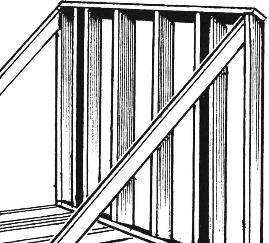
As already noted, the roof is pre-assembled on the ground from 50×100 mm timbers. First, the rafters of one side are connected to the ridge and the lower longitudinal strip. The rafters of the other side are conveniently secured by placing the first half-assembly on the ground: since the angle between the slopes is 90°, the rafters of the second side will take a convenient vertical position for work. The rafters of both slopes are fastened with transverse bars.
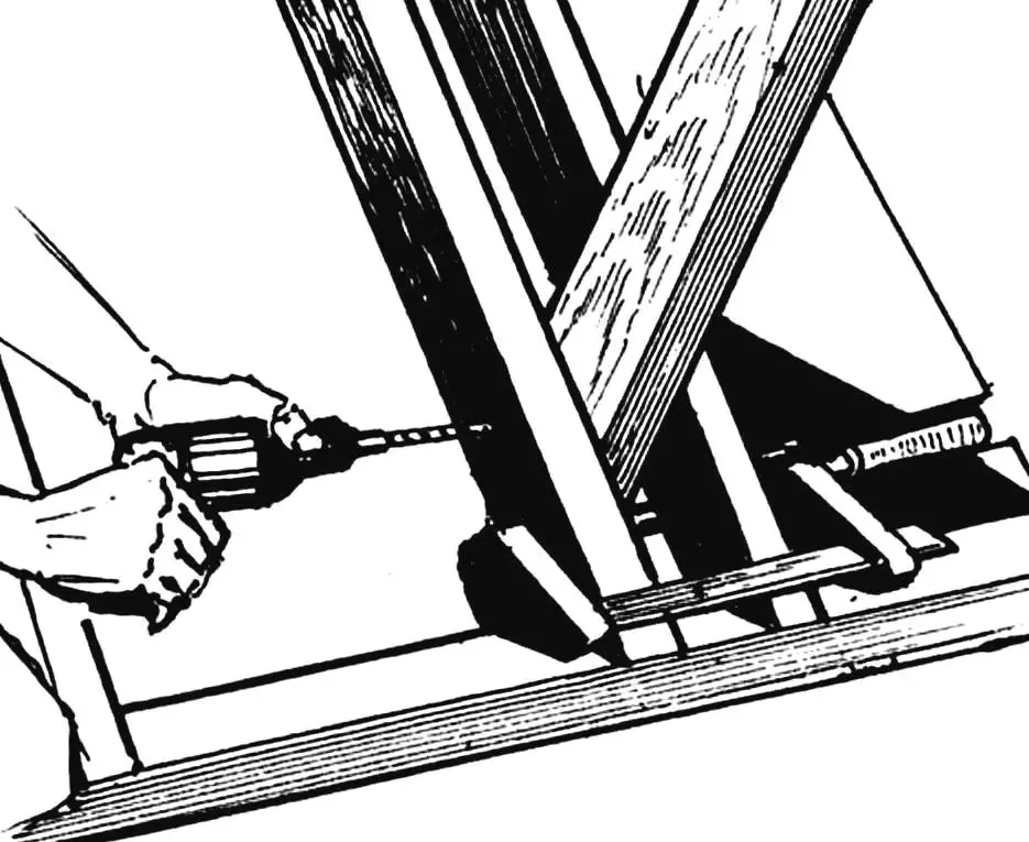
Before proceeding to install the roof frame on the load-bearing posts, grooves for the ridge beam must be made in their upper part. The four roof supports are connected to the load-bearing posts with a tenon, with inclined grooves; they are fastened to the rafters with bolts.
Before installing the roof on the supports, its slopes are prepared for sheathing, which consists of three layers. The first, lowest (battens), can be board or plywood, laid directly on the rafters. Roofing felt is laid over this layer, and on top of it — ceramic tiles, modern metal-plastic tiles, or slate. The end sides of the roof can be sheathed with boards.
The construction is completed by installing a wooden windlass or metal wheel-pulley with a wooden bucket tied to a rope or chain.
«Modelist-Konstruktor» No. 4’2008, based on materials from the magazine «Mechanic Illustrated» (England)
Recommend to read
 SEALANT – SKI-WAX
In the kitchen under the sink plastic drain from the knee all the time leaking water. Not only that I did: the gaskets were replaced, and wrapped the connections with electrical tape and...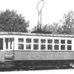 THE EVOLUTION OF THE BIAXIAL
From the history of the tram car. The fact that on the tram lines of the country "standard" rolling stock occupied by the end of 1930-ies a dominant position, does not mean that he was...
