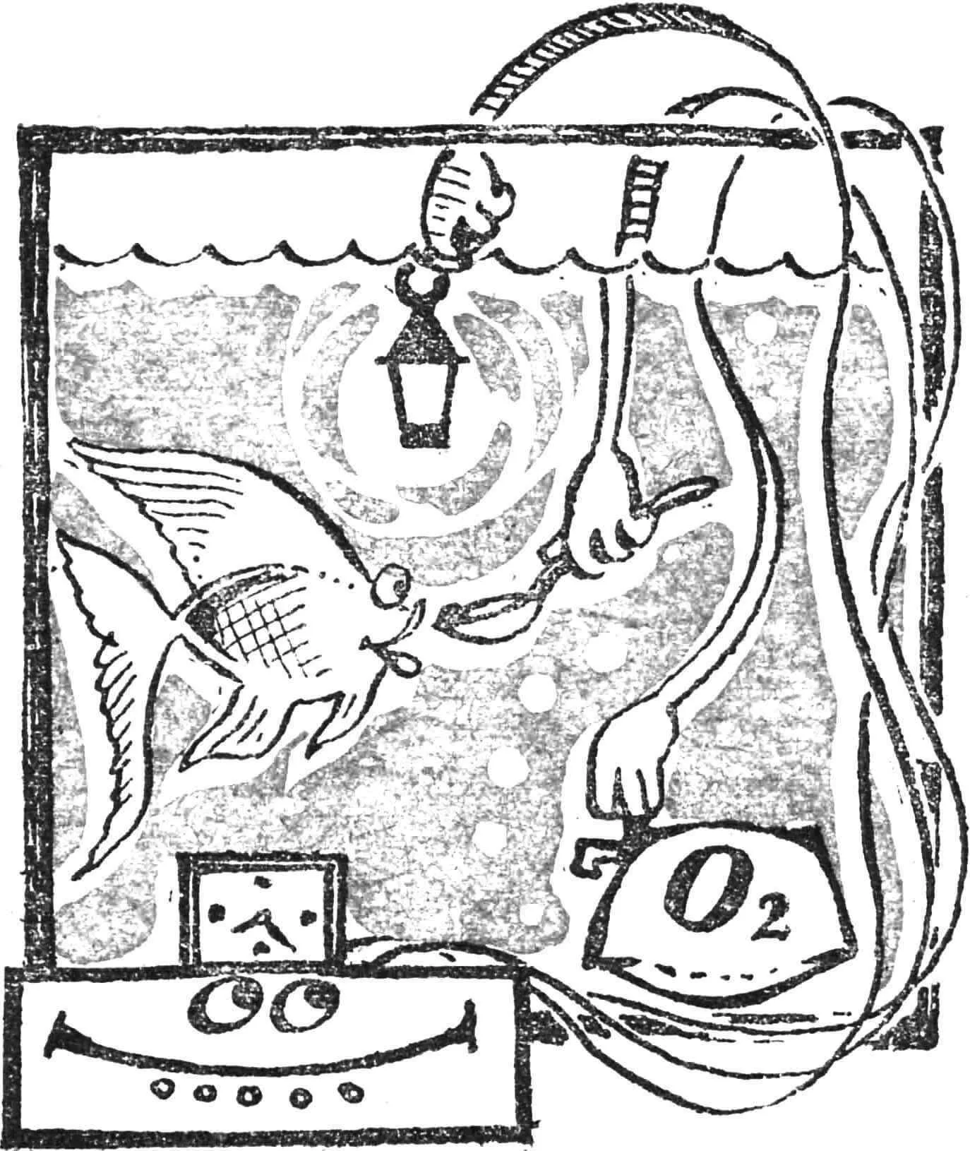
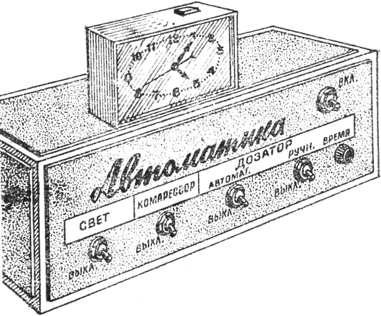
Summer vacation time is approaching. To the numerous concerns related to preparing for the upcoming vacation, aquarium owners have one more: how to provide everything necessary for the underwater inhabitants during the owner’s absence. If you have no one to entrust your aquarium to, entrust its care to an automaton (Fig. 1) and rest peacefully.
On commands coming from the “Slava” electromechanical clock, the automatic assistant will feed the underwater inhabitants at a set time, refresh their water, and turn the light on and off. For this purpose, through connectors installed on the back of the housing, the clock, lighting lamps, compressor, and dispenser are connected to the automaton.
The lighting is controlled using contacts S4, S5 (Fig. 2), installed under the clock hands. When toggle switch S2 is on and contact pair S4 is closed, relay K1 operates and blocks itself with its contact system K 1.3, while K1.1 and K1.2 turn on the lighting lamp H1. It will burn until the hand opens contact S5, de-energizing the K1 relay winding. With toggle switch S3, the light can be turned on at any time or the operation of relay K1 can be checked.
The compressor control device is identical to the previous one, with only lamp H1 replaced by electric motor Ml. But the dispenser automation is more complex. If toggle switch S7 and clock contact S10 are closed, relay K5 operates, which turns on (K5.2) a standby multivibrator on transistors V14, V15 and relay K4 (K5.1). At the same time, it disconnects the multivibrator with its contact pair K4.1, preventing it from operating several times in a row while the K5 armature is attracted. The multivibrator oscillation period is set by the chain C3, R6, R7.
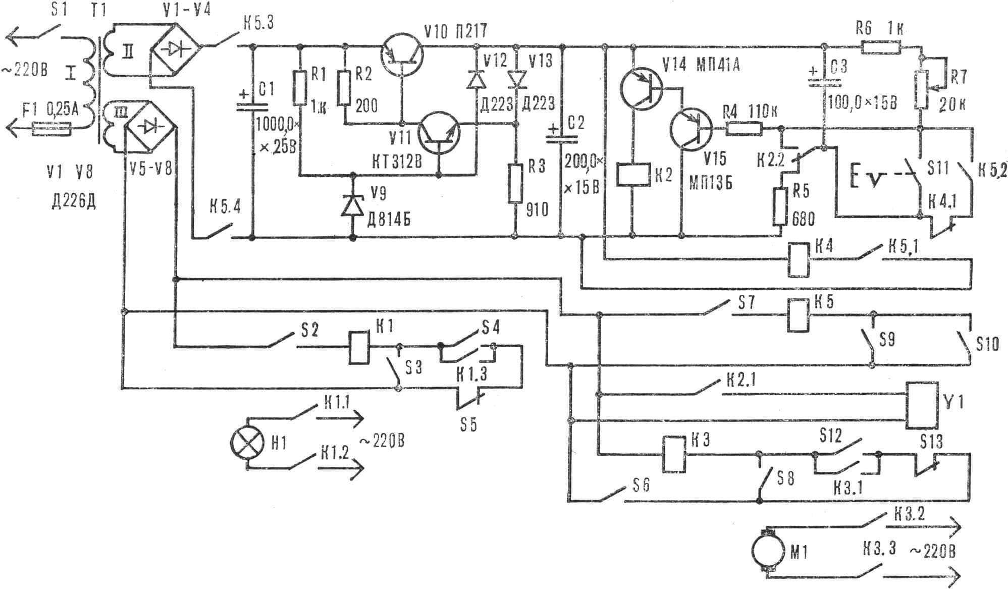
In the initial state (contact plates K5.2 are open), capacitor C3 is connected through resistor R5 to the power source — transistors V14, V15 are closed. When contact K5.2 is restored, capacitor C3 is connected in parallel to resistors R6 and R7. A negative bias voltage appears on the base of V15 and semiconductor triodes V14, VI5 will open. Relay K2 blocks (K2.2) contact pairs K4.1, K5.2 and turns on (K2.1) the electromagnet Y1 winding. Capacitor C3 discharges, and after some time (it depends on the resistance R6+R7) relay K2 releases.
Switch S9 and button S11 are used to test the multivibrator.
The power supply consists of a power transformer with two step-down windings, bridge rectifiers V1—V4, V5—V8, and an electronic voltage stabilizer on transistors V10, V11.
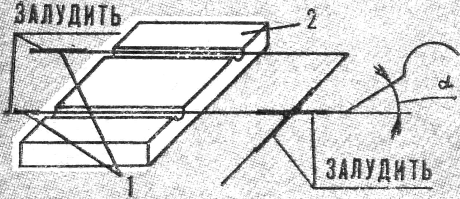
1 — wire, 2 — base.
Now about the parts and construction. Contact pairs S4, S5, S10, S12, S13 are homemade. They consist of wire segments PEL or PEV 0.51, 45 and 50 mm long, installed under the clock hands on plastic platforms measuring 5X10X2 mm. At a distance of 10 mm, the wire is stripped and tinned on one side: the automatic device is connected here. Then, stepping back 20 mm, a 15 mm long section is stripped and tinned. The remaining part of the longer wire is bent at a right angle. Contact pairs are installed in slots on the platforms and glued (Fig. 3). If the contact is closing, the right-angled bend should be under the straight wire and not touch it. For opening contacts, the mutual arrangement of wires making up the contact pair is reversed. In both cases, the clock hand runs onto the section bent at an angle α ≈ 30°.

1 — shutter, 2 — rubber suspension, 3 — hopper, 4 — base, 5 — distribution block, 6 — electromagnet.
The dispenser (Fig. 4) is made of transparent plexiglass. The electromagnet coil contains 4300 turns of PEL 0.25 wire, wound on an insulating frame 30 mm long. It consists of a base Ø 10 mm, with two cheeks 1—2 mm thick glued to its ends (Fig. 5).
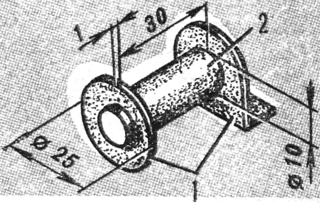
1 — cheek, 2 — base.
The automaton uses MLT-0.5 or VS-0.5 resistors, electrolytic capacitors K50-6, K50-3. Relays K1, K3 MKU-48 (passport RA4.500.457 or RA4.500.232), K2, K4 RES-9 (passport RS4.524.200 or RS4.524.201), K5 RES-22 (passport RF4.500.131). Relay K2 must be adjusted so that it operates at a voltage of 7 V, and for K5, the contact system must operate in this order: K5.3, K5.4, then K5.1 and last K5.2.
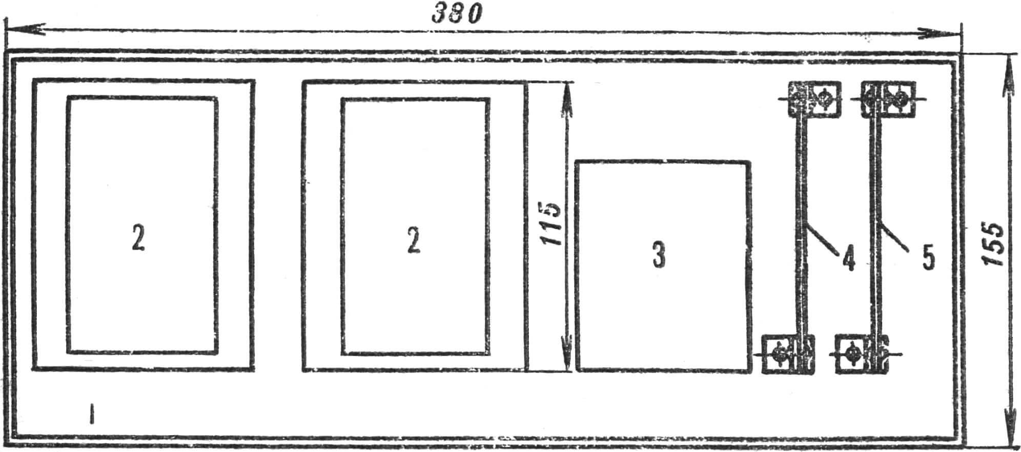
1 — housing, 2 — MKU-48 relay, 3 — transformer, 4 — rectifier board, 5 — dispenser board.
Power transformer T1 is ready-made, with a power of at least 20 W, with secondary winding voltages of 24 V and 15 V. The stabilizer, diodes, and electronic part of the dispenser are mounted on two getinax boards measuring 115X115 mm. The schematic arrangement of elements in the automaton housing is shown in figure G.
The top of the housing is covered with colored decorative plastic or “wood grain” film.
L. CHISTYAKOV, Kyiv
Recommend to read
 BRISTOL “BLENHEIM”
SB was briefly the fastest bomber in the world. In June 1936 in the UK launched the "Blenheim" at about 30 km/h. This aircraft was created initially as a high-speed passenger type "142",... THE ENGINE OF THE “BURAN”: REVEAL RESERVES
The engine RMZ-640 "Buran" Rybinsk engine production plant is widely used not only on the same snowmobile, but deltalyo. However, if a separate snowmobile owners its characteristics...
