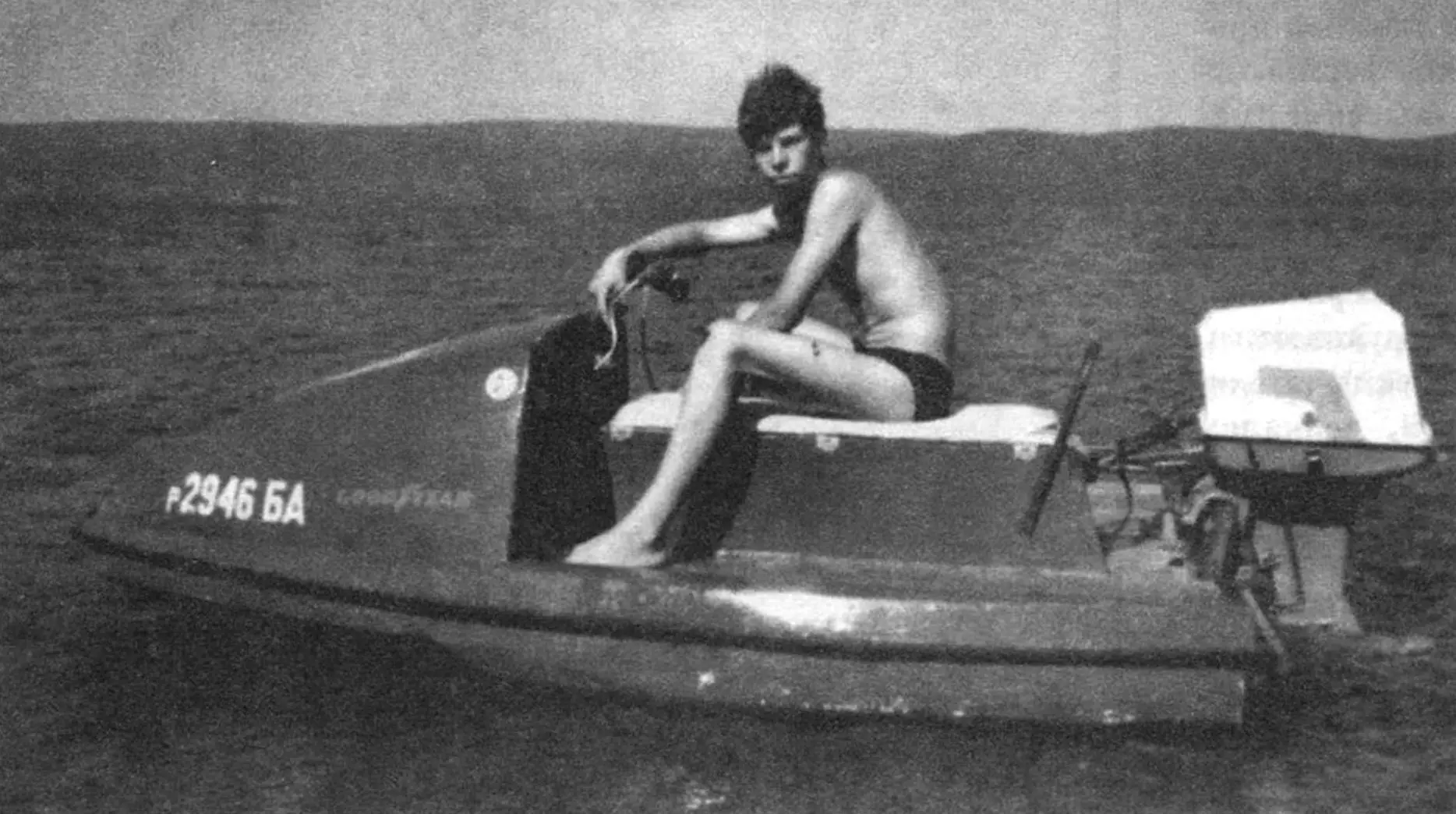
Readers of our magazine are already familiar with the best examples of technical creativity by S.P. KOROVIN, a designer from Kumertau (Bashkortostan). In “Photo Panorama” (see “Modelist-Konstruktor” No. 1’2000), his most famous designs were presented: the “Visit” aircraft, a children’s car, the seven-seat “Orbita-1500” car, and a jet ski (personal watercraft). Later, readers appreciated another development by Stanislav Petrovich — the “ASKOR” minibus (see “Modelist-Konstruktor” No. 4—5’02). Now we present “Marlin” — an improved version of the personal watercraft previously published in “Photo Panorama.” “Marlin” surpasses its predecessor in maneuverability, convenience, and design.
There are many rivers and lakes in Bashkortostan where people can spend weekends wonderfully on the shore. On many fine summer mornings, the Korovin family got into their “Orbita-1500” and drove to the nearest body of water. But relaxing only on the shore is one thing; relaxing on the water is another. Stanislav had a motorboat, but transporting it required a rather bulky trailer. So they never actually took the boat with them…
Once, while looking through technical literature, Stanislav suddenly understood how to solve the water recreation problem at last. In one technical magazine he saw a drawing — three projections of a personal watercraft with overall dimensions. And a short explanatory text. Stanislav remembers only that the craft was called “Marlin.” He later kept this name for his own machine as well, although he developed its power layout and manufacturing technology independently. He also tested this new design himself.
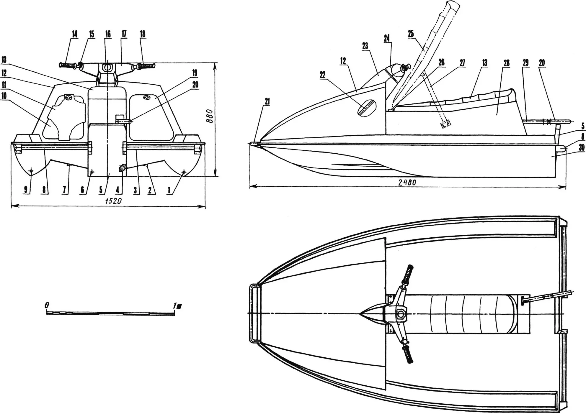
1,9 — holes for draining water from the hull; 2,7 — longitudinal spray rails; 3,8 — transom handrails; 4 — bracket for an external water pressure pickup (speed sensor); 5 — transom board; 6 — hole for draining water from the aft luggage compartment; 10 — left hatch of the bow luggage compartment; 11,19 — removable hatch covers; 12 — bow luggage fairing; 13 — two-seat saddle; 14 — left handlebar grip; 15 — starter button and “stop” switch; 16 — speedometer; 17,24 — halves of the decorative steering cover; 18 — right handlebar grip with carburetor throttle control (throttle grip); 20 — engine turning rod; 21 — bow handrail with brace; 22 — steering shaft; 23 — steering fairing; 25 — seat in raised position; 26 — seat hinge; 27 — raised-seat latch; 28 — wall of the aft luggage compartment; 29 — steering linkage; 30 — hull bottom
Designing and building the watercraft took several winter and spring months. In summer, Stanislav mounted a “Veterok” outboard motor (eight horsepower) onto the transom board and launched the “Marlin”… into the city pond. With one rider, the craft even got onto plane there! But for two people, the “Veterok” motor power was insufficient.
Later, another engine was tested — an unusual combination of “Vikhr” and “Privet.” The point was that in the “Rotor” ultralight aviation club, where Stanislav worked, the upper parts of “Privet-22” outboards were used to make engines for hang gliders. And all corners of the club were piled with unused lower units. In one corner there was also a “Vikhr-30E” with electronic contactless ignition that delta pilots did not want.
Without hesitation, Stanislav made an adapter plate from duralumin, turning the “Vikhr” on it so that it could both mate with the “Privet” column and fit under its cowling.
The very first tests of “Marlin” with the new engine showed: this is exactly what was needed! At a speed of 50 km/h, the craft confidently got on plane and easily towed a water skier.
To transport his machine, the designer built a nimble trailer cart with rubber-lined supports. Together — his wife Olga took the bow rail, and Stanislav took the transom handrails — they lifted “Marlin” and placed it onto the trailer. Then they put the outboard motor in the car trunk and drove from the garage home to pick up the children, so the whole family could go out of town to the water. Often to fairly distant places. For example, the Korovins repeatedly stayed on the shores of the Nugush reservoir, located 80 km from Kumertau.
“Marlin” stays on the water very well. It can only be capsized with great effort. Therefore, unlike similar imported machines, you can fish from its deck (there is enough room to store the catch), not fear waves from a passing vessel, stand at full height calmly, and an adult can climb aboard from the water not only from the transom but even from the side. “Marlin” heels but does not overturn.
And what about handling? It is so simple and light that Olga, who had never touched a car or motorcycle steering control before, mastered it on the first try!
In addition, the Korovin craft is quite inexpensive to operate, because it runs on affordable A-76 gasoline, while imported watercraft require expensive AI-95 and equally expensive imported oil.
HULL DESIGN
The hull of the personal watercraft consists of many isolated compartments: bow and aft luggage compartments, as well as twelve (six per side) sealed side volumes formed by frames, longitudinal walls, deck, and bottom. In addition, the sides also add buoyancy, since they too are small but sealed cavities.
The structural materials used to build “Marlin” are fiberglass (a multilayer composite of glass cloth, mostly grade T-25, and epoxy binder) and foam plastic (mostly grade PS-200). Duralumin, stainless steel, plywood, wood, and synthetic leather were used for individual assemblies and parts.
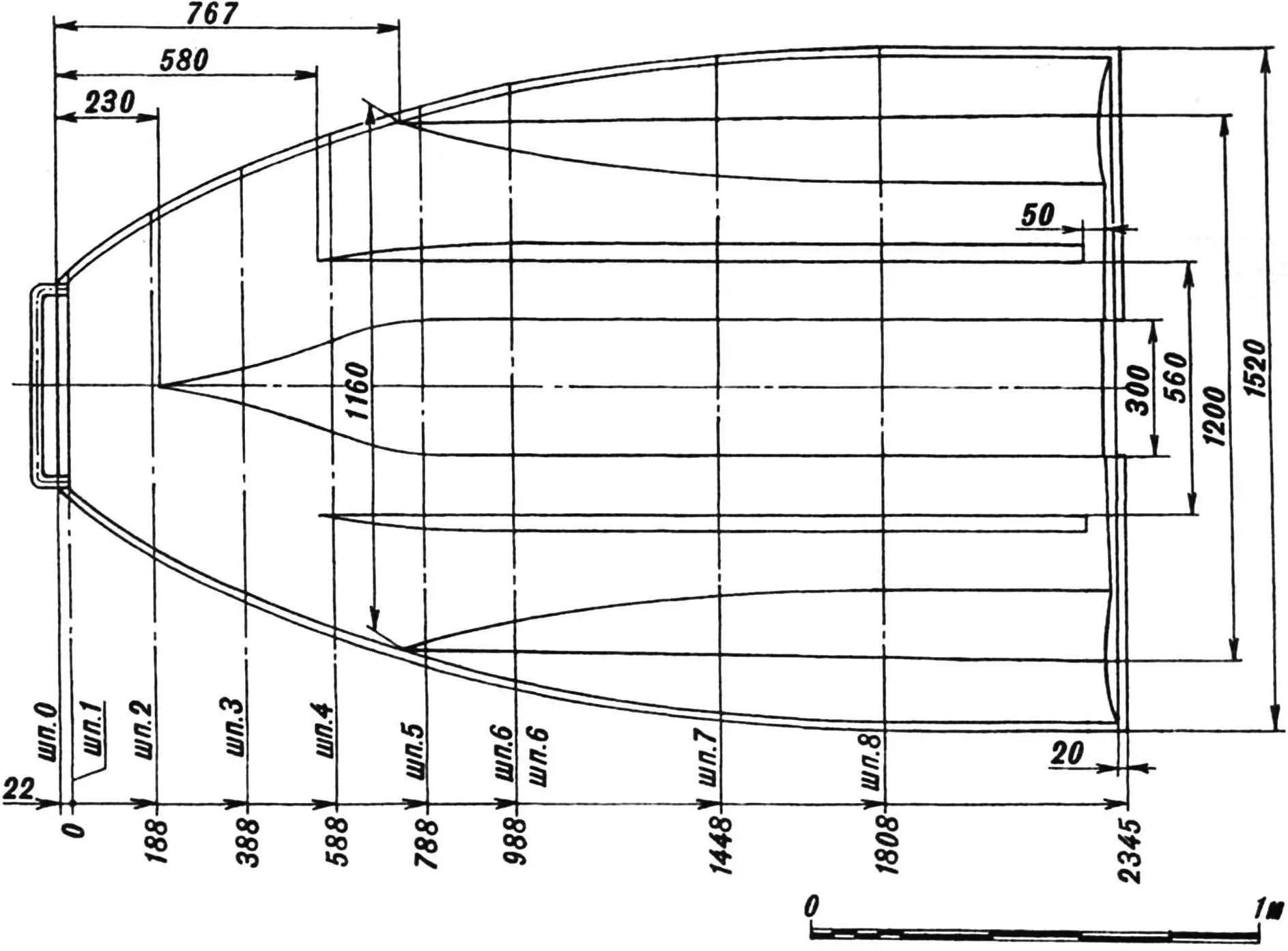
The hull was made in sections. The bow luggage fairing, bottom, and sides were laminated separately over plywood molds (usually from four layers of fiberglass cloth with epoxy adhesive). The fairing is reinforced inside by three upper stringers and four diagonal overlays, and the bottom by four stringers (inside) and two longitudinal spray rails (outside). All these reinforcements are foam strips of various cross-sections covered with fiberglass tape. A powerful keel beam is also bonded into the bottom — a thick-walled duralumin profile, to the front end of which a shoe bearing for the steering shaft is bolted.
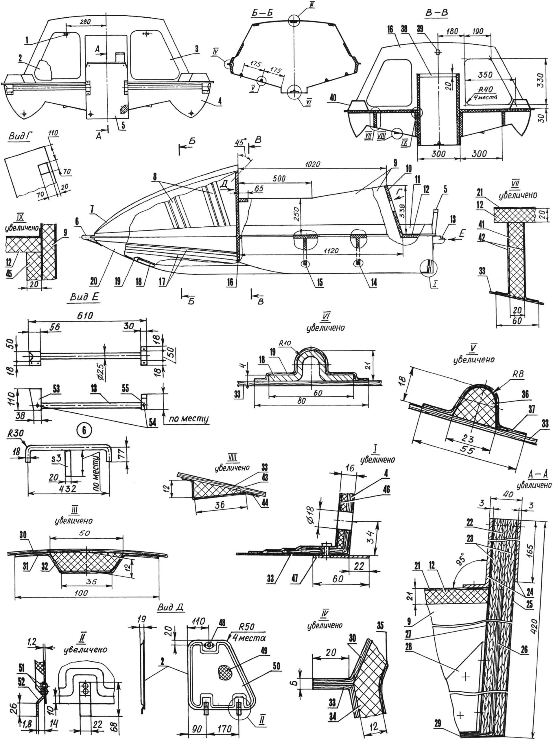
1 — lock hinge of the left bow luggage hatch cover; 2,3 — bow luggage hatch covers; 4 — transom (foam); 5 — transom board; 6 — bow handrail with brace (titanium, tube 18×1; sheet s3); 7 — bow luggage fairing; 8 — right diagonal overlays; 9 — side walls of the aft luggage compartment; 10 — end wall with opening for steering linkage; 11,40 — gunwales (4 fiberglass layers each); 12 — deck (foam); 13 — left transom handrail (D16T, tube 25×2); 14 — frame No. 8; 15 — frame No. 7; 16 — frame No. 6; 17 — bottom stringers; 18 — keel beam (D16T); 19 — keel beam shell (2 fiberglass layers); 20 — bottom; 21 — deck covering (2 fiberglass layers); 22 — transom board core (plywood s5); 23 — outer layers of transom board (plywood s12); 24 — transom board overlays (D16T, sheet s3); 25,27 — transom board laminations (4 fiberglass layers each); 26 — transom (fiberglass laminate s5); 28 — right gusset (D16T, sheet s3); 29 — keel part of the bottom (4 fiberglass layers); 30 — shell of bow luggage fairing (4 fiberglass layers); 31 — upper stringer shell (2 fiberglass layers); 32 — upper stringer (foam); 33 — bottom shell (4 fiberglass layers); 34 — left side stringer (foam); 35 — side stringer shell (2 fiberglass layers); 36 — bottom stringer (foam); 37 — bottom stringer shell (2 fiberglass layers); 38 — seat mount bracket (oak, bar 65×20); 39 — steering shaft opening; 41 — left partition (foam); 42 — partition lamination (one fiberglass layer each side); 43 — longitudinal spray rails (foam); 44 — spray rail shell (2 fiberglass layers); 45 — left deck support (foam); 46 — transom lamination (4 fiberglass layers); 47 — hull water drain hole; 48 — hood lock; 49 — filler (foam); 50 — sheathing (2 layers of T-10 fiberglass); 51 — rivets Ø3; 52 — hook (D16T, profile s1.8); 53,55 — handrail mounting brackets (titanium, sheet s3); 54 — rivets (steel, tube 8×1)
After joining the bow fairing and bottom, their joint line was also reinforced inside with two side stringers — wide foam strips and equally wide fiberglass tapes on epoxy adhesive. Outside (at the front), the fairing and bottom are additionally fastened by a bow handrail made of 18×1 mm titanium tube.
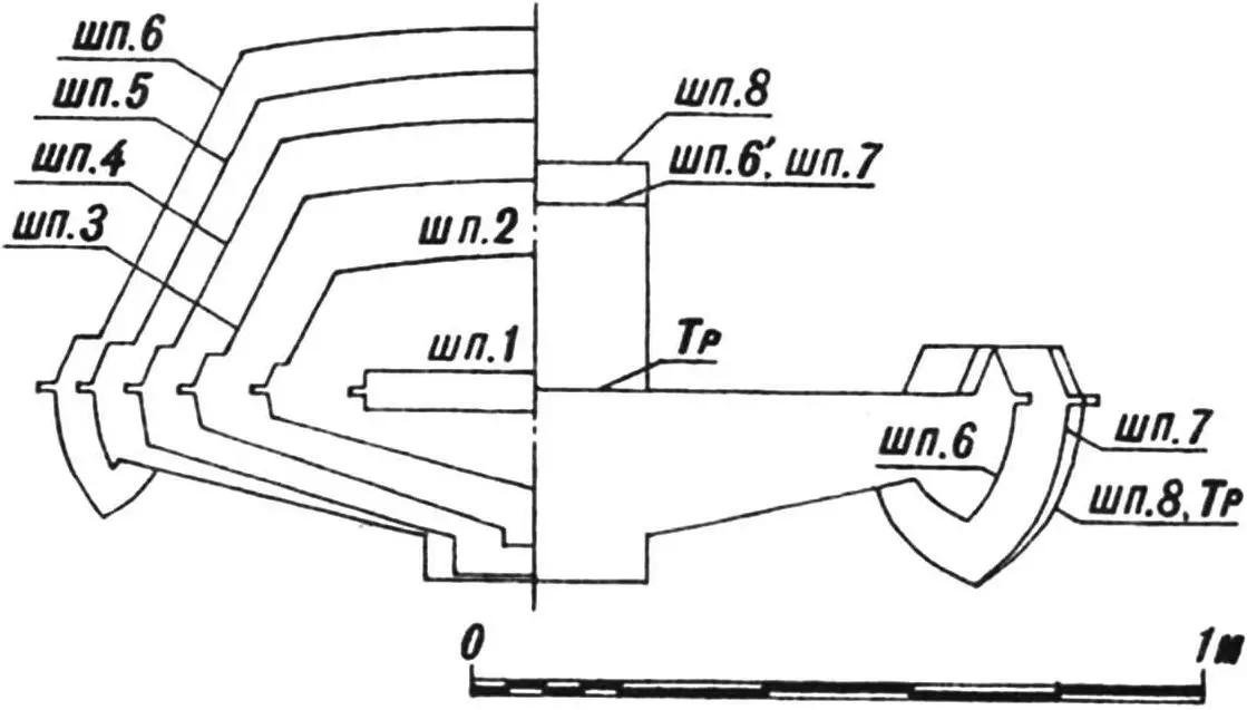
The first physically real frame, No. 6 (frames No. 1—5 are nominal), is cut entirely from 20 mm foam sheet, laminated with fiberglass on both sides, and inserted into its opening, where it separates the bow luggage compartment from the rest of the hull volume. This frame is not solid: in the center, there is an angled drilled hole for steering shaft exit, and on the sides, two luggage hatches with removable covers are cut. (The covers are equipped with quick-release hood locks that can be opened with a screwdriver tip or even the edge of a coin.) Frames No. 7 and 8 are similar to No. 6 in composition: foam and one fiberglass-with-epoxy layer on each side.
The hull structural scheme is complemented by four longitudinal elements made of 20 mm foam laminated on both sides: two partitions extending from frame No. 6 to the transom and hidden under the deck, and two walls rising above the deck and forming the volume of the aft luggage compartment. At the rear, they are connected by an end wall with a square opening for the steering linkage passage, and on top of them sits a folding two-seat cushion made of foam rubber and synthetic leather. The seat is hinged with two small window hinges to a bracket (an oak bar bonded between the walls near frame No. 6), and in folded-up position it is held by a simple latch made of duralumin parts.
The transom is formed by building up the aft end of the bottom from inside with fiberglass-and-epoxy layers to a thickness of 5 mm. Then, also from inside, the transom is reinforced with a 5 mm foam layer (except for the central zone where the transom board fits), and finally with four more layers of fiberglass.
Outside, the hull is riveted along the transom contour with a stainless steel strip protruding below the hull by up to 22 mm. This protrusion is needed so that water jets during planing do not cling to the transom and create additional bottom drag. Holes are drilled in the transom to drain water that seeps into the compartments. The holes are closed with tight plugs.
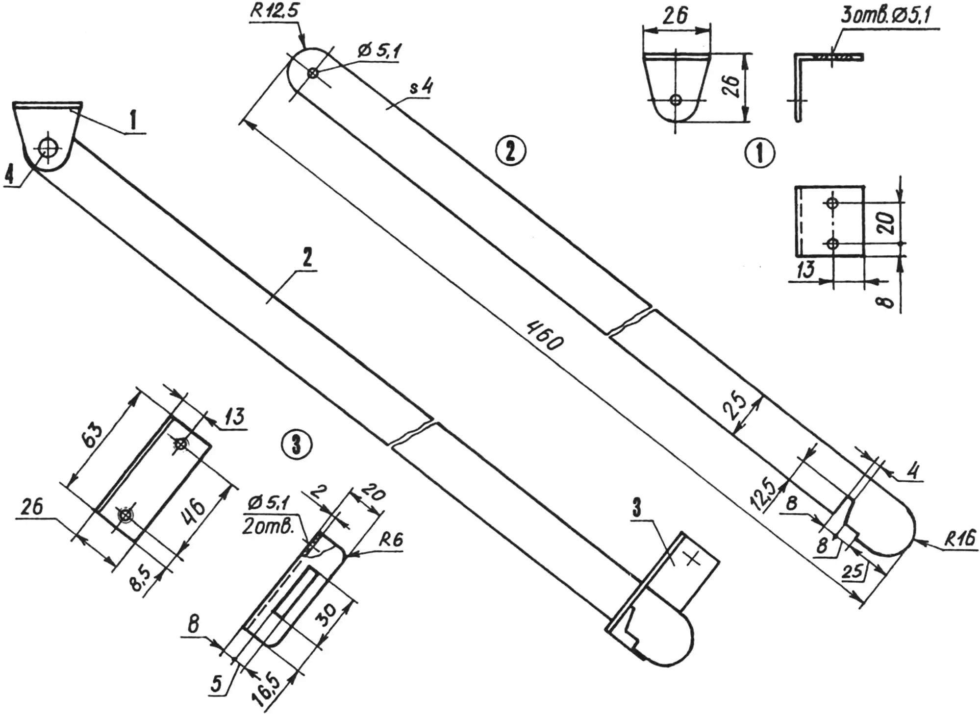
1 — hinge (D16T, angle 26x26x2); 2 — lever (D16T, sheet s4); 3 — stop (D16T, angle 26x20x2); 4 — rivet Ø5 (AMts)
A transom board is installed with epoxy adhesive onto the central transom zone, and the outboard motor is mounted to this board. The board consists of three plywood layers of different thickness. After installation onto the transom, it was laminated on both sides with fiberglass (four layers each) and reinforced with two duralumin overlays under the motor clamp area. This entire package is tightened along the contour with six M5 bolts through the overlays, and the flange of the front overlay is additionally fastened to the deck with three screws.
Since the main engine load is transferred to the hull through the transom board and the walls of the aft luggage compartment, the joints between the board and the walls deep inside the compartment are reinforced with two triangular gussets made of 3 mm duralumin sheet. Each gusset is pulled to the board by its 20 mm rear flange using four screws with epoxy adhesive, and by its triangular plane to its wall with four through M5 bolts.
Outside, handrails made of duralumin tube are attached to the transom and transom board with M5 bolts; their brackets are riveted from sheet titanium. Among other things, these handrails are used when towing a water skier. The tow line (nylon cord 5 mm in diameter and 30 m long) is attached by a carabiner to the outer handrail brackets.
The deck of the watercraft is also made from 20 mm foam sheet laminated with fiberglass on top. The deck rests on frames No. 7 and 8, longitudinal partitions, and the ends of the aft luggage walls, and also on supports made from 20×20 mm foam bars bonded with epoxy to the aft luggage walls. Along its contour, the deck is bonded to frame No. 6, the bottom-to-side joint, and the transom.
One more detail: in the lower left corner of the transom board there is a hole for draining water accumulated in the aft luggage compartment, closed by a tight plug, and in the lower right corner there is a bracket for an external pickup of incoming water flow pressure (speed sensor). The pickup is connected to the speedometer by a thin rubber hose laid along the aft luggage wall and routed through a special opening in the end plug of the compartment at deck level. In one bundle with this hose are also the battery cables and the throttle cable from the handlebar carburetor throttle control. From the same end plug, the fuel hose is led out through another opening, with an in-line priming bulb inserted.
STEERING CONTROL
All controls of the watercraft are concentrated on the handlebar located at the cut of the bow luggage fairing. The steering shaft — a 20 mm steel tube — rotates in two bearings: in the socket of a U-shaped shoe bolted to the keel beam, and in a polyurethane washer built into the decorative steering cover. A handlebar crossbar made from 25 mm steel tube is welded to the top end of the shaft; motorcycle grips are fitted onto its “horns” (the speedometer and controls are also motorcycle-type here).
The first “Marlin” had no decorative fiberglass steering cover. But in the new version it appeared and, it must be said, significantly improved the craft’s design. At least now it looks complete.
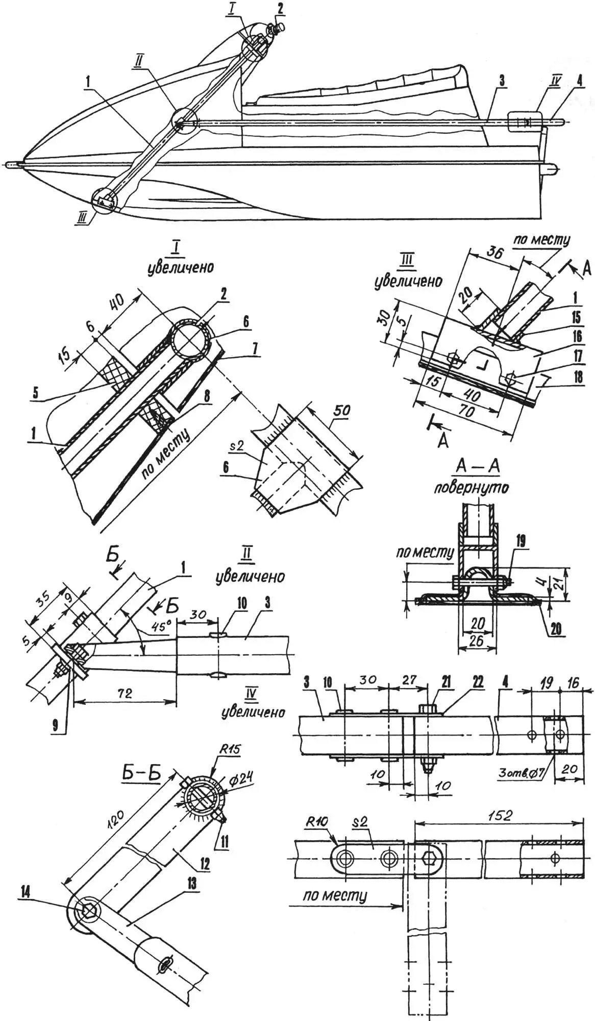
1 — steering shaft (steel, tube 20×1.5); 2 — handlebar (steel, tube 25×2); 3 — steering linkage (D16T, tube 25×2); 4 — engine turning lever (D16T, tube 25×2); 5 — support bearing (polyurethane); 6 — plate (steel, sheet s2); 7 — decorative cover (fiberglass); 8 — self-tapping screw 3×10 (8 pcs. around contour); 9 — spherical bearing ShS-6; 10 — tubular rivets (steel, tube 6×0.5, 3 pcs.); 11,14,17,19 — bolts with self-locking M5 nuts; 12 — steering arm (steel, tube 24×2, sheet s5); 13 — tip (steel); 15 — socket (steel, tube 26×3); 16 — shoe (steel); 18 — keel beam (D16T); 20 — keel (bottom, fiberglass); 21 — bolt with self-locking M6 nut; 22 — shackle (steel, sheet s2, 2 pcs.)
Approximately in the middle of its length, the steering shaft has a steel arm pivotally connected to a fairly long duralumin linkage rod. A spherical bearing ShS-6 press-fitted into the arm end is used as the pivot, colloquially called a “fish eye.” It allows movement through a wide angle range, which is highly relevant in this watercraft control system where steering input through the rod is transmitted to a massive engine, causing it to rotate and change its position on the transom board.
The front end of the steering rod is equipped with a tip for connection to the spherical bearing, while the rear end is connected to a rocker arm mounted on the outboard motor.
The “Vikhr — Privet” engine combination is started with the starter button. If the battery fails, a pull-start cord is used.
Everything needed during a trip is placed onboard “Marlin.” Gear is distributed as follows: a 20-liter outboard fuel tank, tow line, fishing tackle, and other cargo — in the bow compartment; battery, tool box, folding oars, and personal items — in the aft compartment.
* * *
This is not the last modernization of “Marlin.” To explore shallow backwaters inaccessible even to motorboats, Stanislav plans to equip his watercraft with a water-jet engine, and the machine layout allows such an upgrade. Structurally, his jet unit is already one-quarter complete. So next summer, the Korovin family will probably be found not on the Nugush reservoir…
Main characteristics of the “Marlin” personal watercraft
Length, mm … 2480
Width, mm … 1520
Height, mm … 880
Weight without engine, kg … 50
Maximum speed, km/h … 55
Maximum load, kg … 150
Engine power, hp … 30
Fuel reserve, l … 20
“Modelist-Konstruktor” No. 4’2003, A. TIMCHENKO
Recommend to read
 MACHINE PLASTERER
With the development of industrial building methods became widely used details of full factory readiness. However, there still remains an urgent problem mechanization of plastering and... Foot-powered shower
It is intended for dacha and garden cabins and can also be used in field conditions. The design was approved by everyone who used it for several years. A typical dacha shower is usually...
