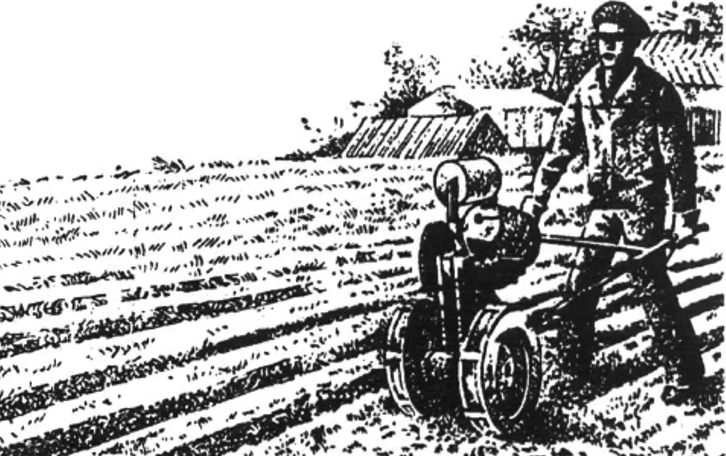
The quiet of a sunny spring morning was broken by the throb of an engine. A villager digging his garden with a spade straightened up and looked over the fence at the neighbor’s plot: what was that noise at the Ilyichyovs’ place? He saw a small two-wheeled machine emerge from behind the outbuilding into the garden, puffing bluish smoke, with the Ilyichyovs’ son, Sergei Alekseyevich, walking behind it, holding the long control handles.
The rural mechanic immediately understood what machine his neighbor had built: the plow hanging at the rear and the control handles of characteristic shape spoke for themselves. The walk-behind plow design was clearly not very complicated. The engine make was familiar to the neighbor. Exactly the same motor, together with parts from a worn-out scooter, lay in his shed under a tarpaulin — he just never got around to repairing it…
Meanwhile, Ilyichyov turned around and, opening the throttle, buried the plow in the soil. Behind him, the first furrow appeared in the ground smoothed by snow and rain. That was the “baptism by fire” of the “Vyatich”, a homemade walk-behind tractor created by design engineer Ilyichyov.
Since then, residents of the Moscow-region village of Morozki often saw the gardener’s mechanical helper at work on the plot. When the potatoes grew bushy, Ilyichyov, changing the wheels and tillage implement, took it into the garden to hill the plantings… When something had to be transported, instead of a plow or hiller, a homemade cart was hitched behind the “Vyatich”. Growling with its engine, the walk-behind tractor confidently pulled a fully loaded cart plus a rider on top — almost half a ton.
When it was time to stock firewood for winter, Ilyichyov’s micro-universal came to his aid. He removed the engine from the “Vyatich” frame together with the mounting bracket and installed it on a simple device with a pendulum disc saw.
The usefulness of a walk-behind tractor in farming is obvious.
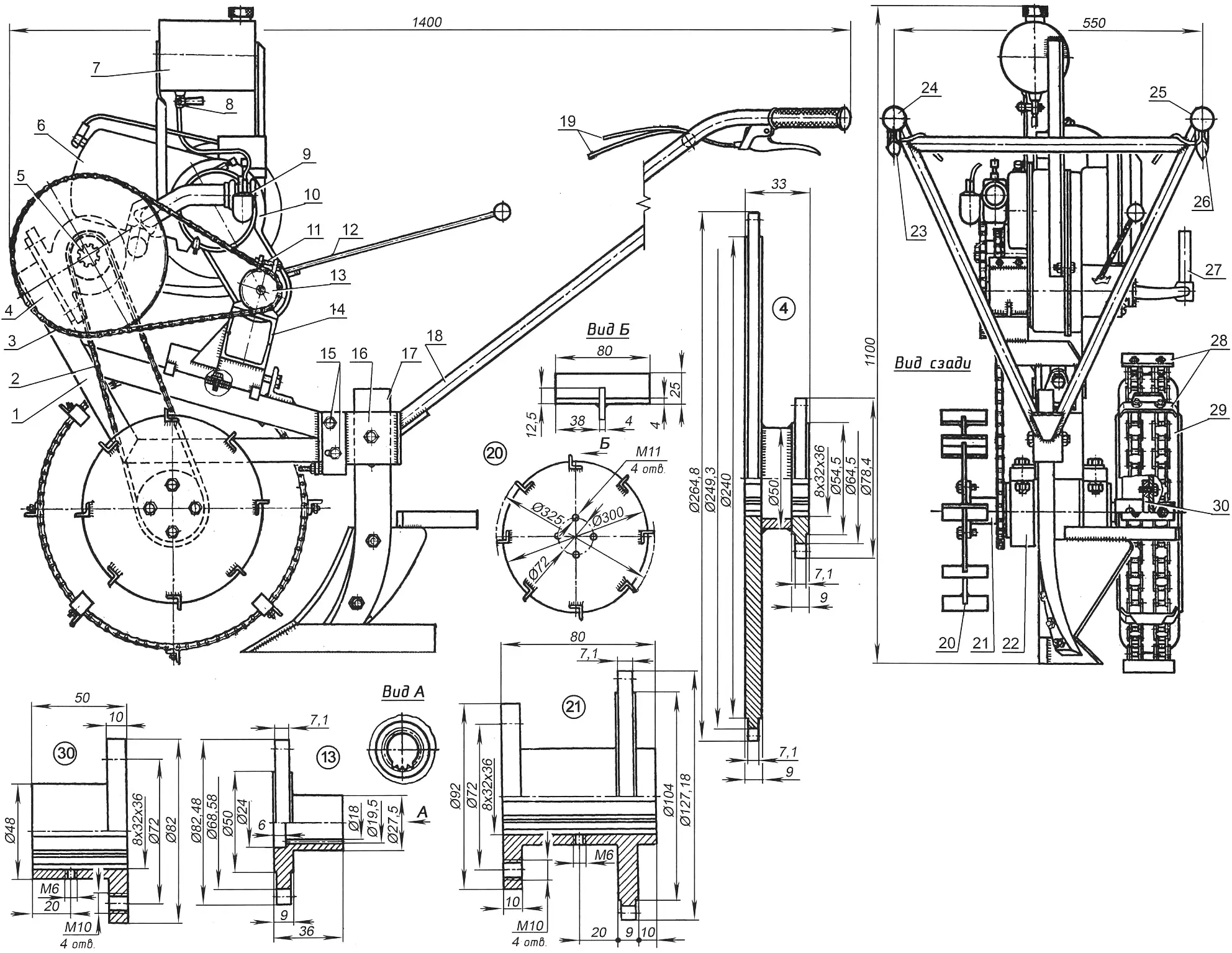
1 — frame; 2 — drive chain; 3 — driving chain; 4 — intermediate sprocket block; 5 — intermediate axle; 6 — engine cowling; 7 — fuel tank; 8 — fuel tank tap; 9 — carburetor; 10 — engine; 11 — engine mounting bolts; 12 — gearshift lever; 13 — output sprocket; 14 — bracket; 15 — holder suspension bolts; 16 — holder clamp; 17 — plow; 18 — control handle tube; 19 — control cables (shown broken for clarity); 20 — support wheel; 21 — drive sprocket; 22 — drive axle housing; 23 — clutch lever; 24 — left control grip; 25 — right grip; 26 — throttle lever; 27 — kickstarter pedal; 28 — lugs; 29 — main wheel; 30 — main wheel flange
This walk-behind tractor can be divided, conditionally, into five parts: the frame, engine group, transmission, wheels, and holder of tillage implements with controls. In that order, let us examine the design of the “Vyatich” (Fig. 1).
The frame (Fig. 2) is welded from three beams — sections of channel No. 8. In the wall of the upper beam, M8 threads are cut in two holes for mounting the engine bracket. There, slightly below the holes, a central support is welded — an angle with an M8x60 mm adjusting bolt by which the bracket can be moved along the frame. Why — will become clear later.
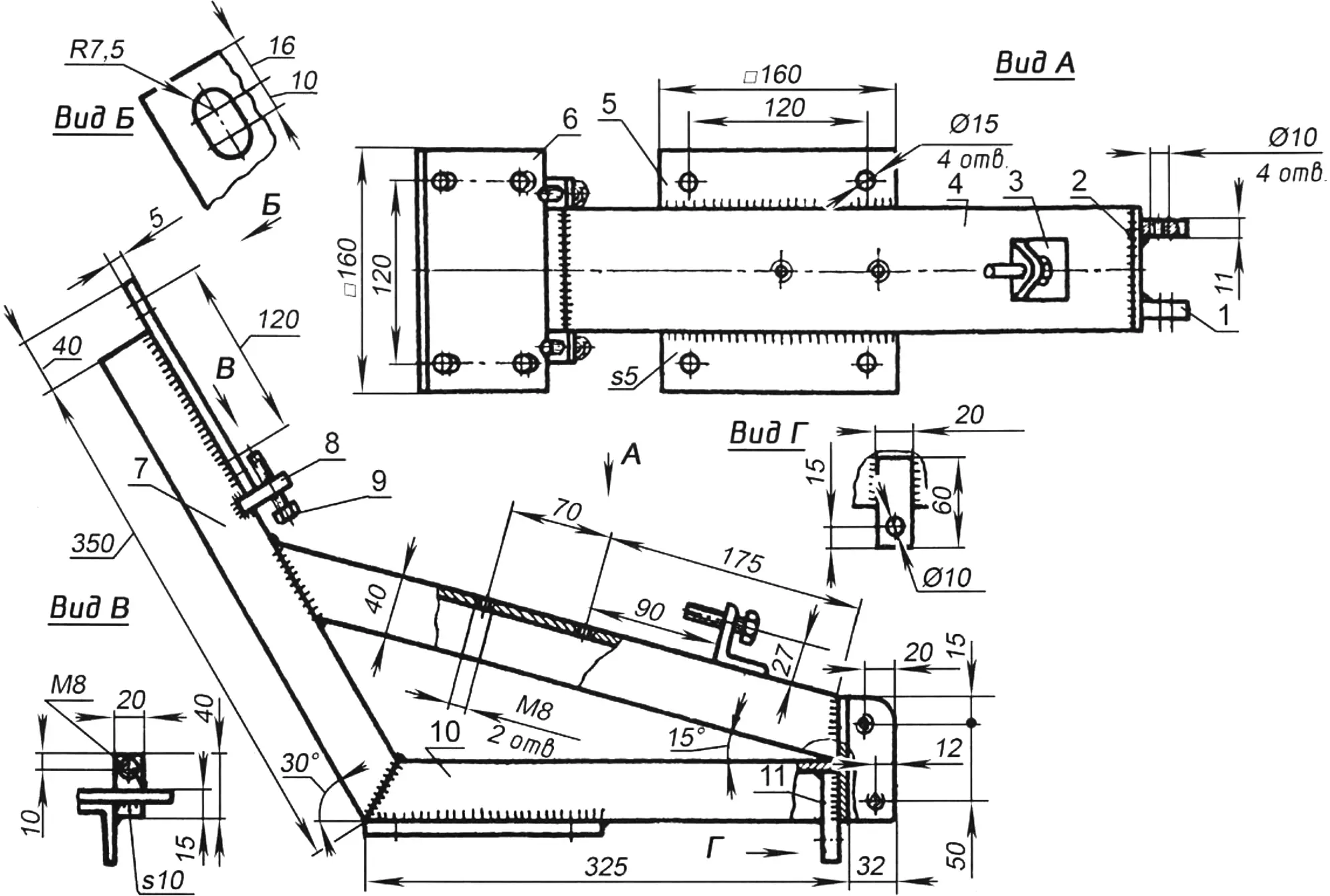
1 — holder suspension hinges; 2 — heel plate; 3 — central support; 4 — upper beam; 5 — drive axle platform; 6 — intermediate axle platform; 7 — inclined beam; 8 — side support (2 pcs.); 9 — adjusting bolt (3 pcs.); 10 — lower beam; 11 — lug
Square steel plates — platforms for the drive and intermediate axles of the walk-behind tractor — are welded to the lower and inclined beams of the frame. The holes in the drive axle platform for fastening its housing are cylindrical. In the intermediate platform they are made as slots, and below the platform two side supports with M8x60 mm adjusting bolts are welded to the flanges of the inclined beam.
A rectangular plate — the heel — is welded to the rear part of the frame, and holder suspension hinges are welded to it on the outside. A lug with a 10 mm diameter hole is welded to the inside of the heel; the holder adjusting bolt enters this hole.
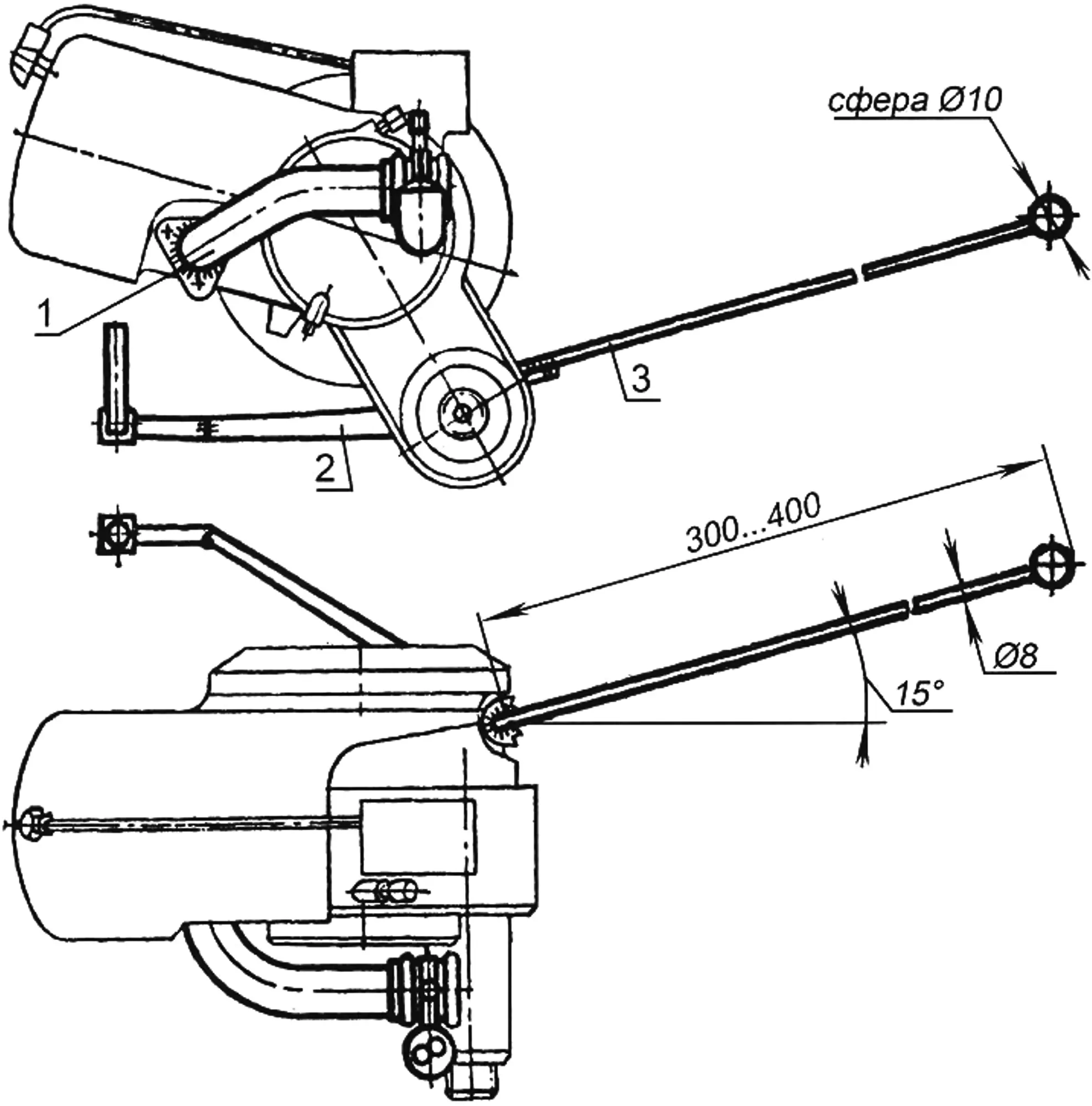
1 — carburetor intake pipe; 2 — kickstarter lever; 3 — gearshift lever
The engine group of the “Vyatich” consists of the engine, the bracket for mounting it to the frame, the output sprocket, and the fuel tank. The engine is taken from the widely known Vyatka-150M scooter (an Electron scooter will also do). It was not subjected to major modifications, but some things were changed. The carburetor pipe (Fig. 3) was separated from the flange, rotated 180° in the horizontal plane, and welded back to the flange (otherwise, when installing the engine on the frame, the carburetor would hit the structure; for the same reason the muffler was removed). The kickstarter lever was notched in two places, bent at the notches, and welded in that form. After that, when starting the engine, the lever no longer caught on the wheel when lowering.
The gear selector sector was also modified. A steel rod with a ball on the end was welded to it, which can easily be reached while standing behind the walk-behind tractor’s control handles.
The output sprocket (Fig. 1) is fitted on the engine power take-off shaft. It has 19 teeth with a 12.7 mm pitch. The splines of the sprocket and shaft match.
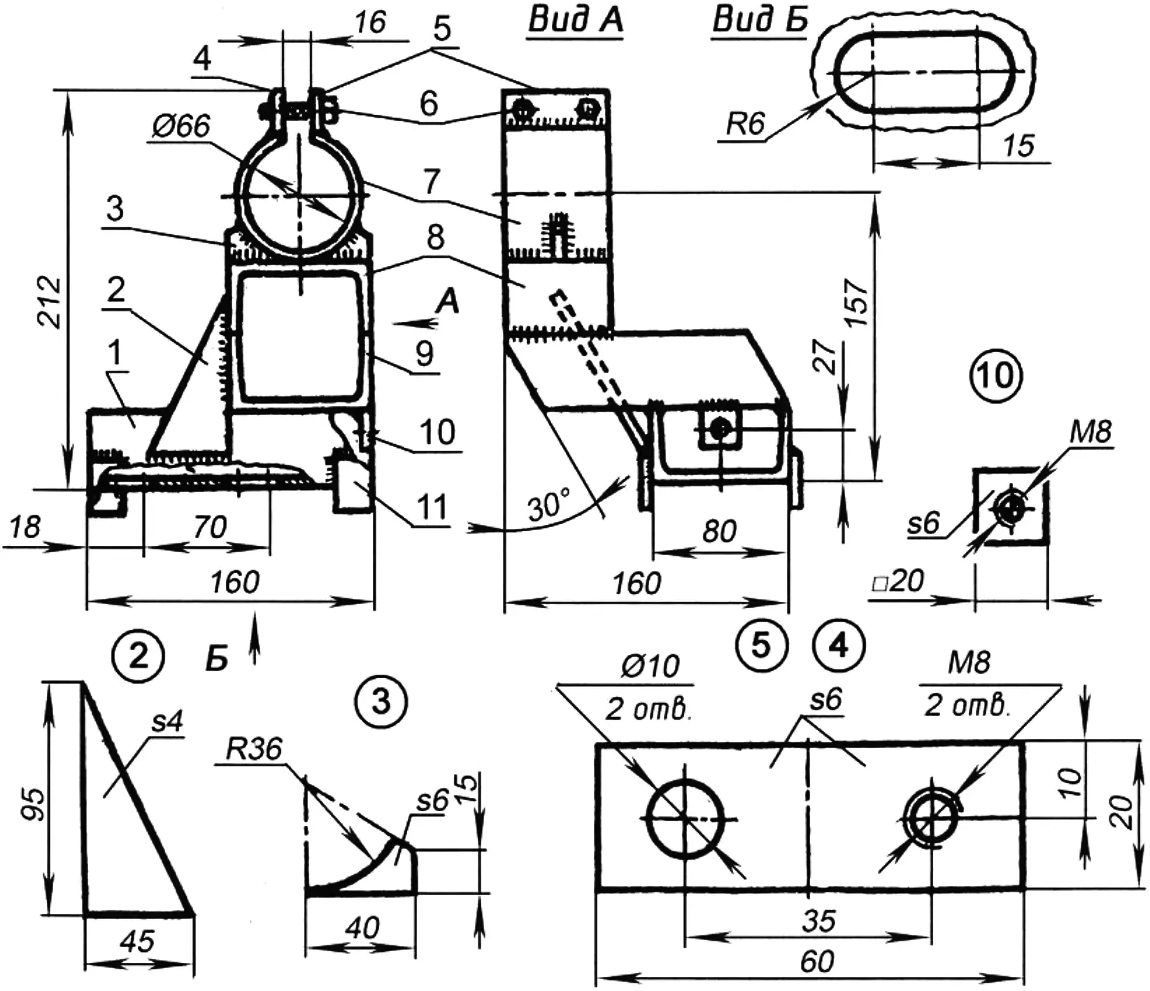
1 — base; 2 — stiffening rib; 3 — prop; 4 — front clamp jaw; 5 — rear jaw; 6 — tightening bolt (2 pcs.); 7 — clamp; 8 — support; 9 — cantilever; 10 — locknut; 11 — stop
The engine is mounted on the frame using a bracket welded from several parts, mainly from sections of channel No. 8 (Fig. 4). The bracket clamp, tightened with bolts, grips the output shaft neck and holds the engine securely. The bracket itself is attached to the frame with two M8x10 mm bolts. For this purpose, slots are cut in its base, which makes it possible to move the bracket along the frame and thereby change the tension of the driving chain (the adjusting bolt in this case turns in a locknut welded to the bottom of the cantilever). And so that the bracket does not skew during adjustment, stops welded to the edges of its base orient the bracket along the upper beam.
The cylindrical fuel tank is mounted on two posts above the engine. Fuel flows from it to the carburetor by gravity.
The transmission consists of the intermediate and drive axles (Fig. 1), taken from scrapped potato harvesters, sprockets, wheel flanges, and chains. The intermediate axle is placed on the platform of the frame’s inclined beam and can move slightly in its slots, tensioning the drive chain. Tension is adjusted with M8x60 mm bolts in the frame’s side supports.
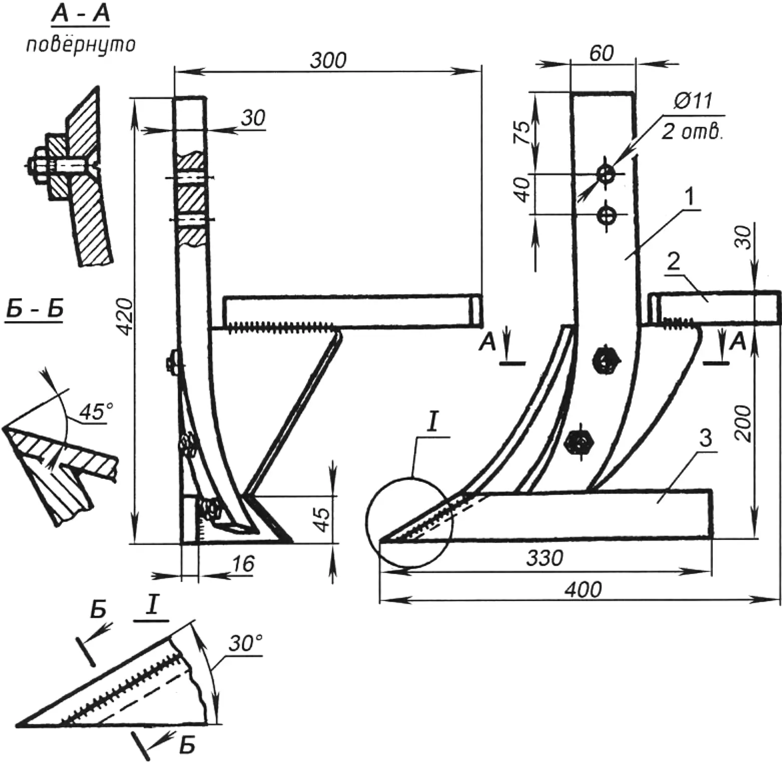
1 — coulter; 2 — deflector; 3 — stop
An intermediate sprocket block is fitted on the left splines of the axle shaft and secured with an M6x8 mm screw. The larger sprocket has 64 teeth, the smaller — 18. The tooth pitch is the same — 12.7 mm. Torque from the engine output sprocket is transmitted by chains from a Jawa motorcycle to the intermediate axle, and from there to the drive axle. There the sprocket has 30 teeth with a 12.7 mm pitch and is made together with the flange for mounting the walk-behind tractor’s left wheel. It is fitted on the splines of the left end of the axle shaft and secured with an M6x8 mm screw. On the splines of the right end of the drive axle, the right wheel mounting flange is installed and secured in exactly the same way.
The wheels on the “Vyatich” are scooter wheels (Fig. 6). Only their mounting discs to the flanges are homemade, cut from steel sheet. For better grip with the soil, the wheels are fitted with lugs — angles with 25 mm wide flanges (eight per wheel). The angles are of two types: half with tabs, half without tabs. They are attached, alternating, to two harvester chains fitted over the tires. So that the chains do not come off, the tabs on the lugs are bent toward the wheels.
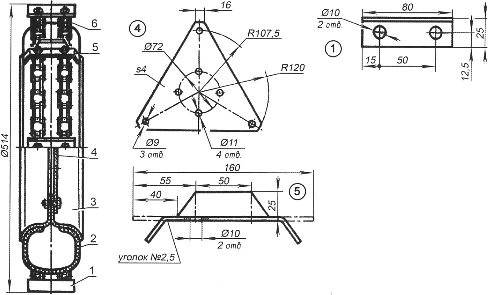
1, 5 — lugs; 2 — wheel; 3 — rim; 4 — disc; 6 — chain
During plowing, the left scooter wheel is removed and a support wheel is installed in its place. It is entirely metal (Fig. 1): the disc is cut from steel sheet, and eight lugs — from angle with 25 mm wide flanges. The angles are joined to the disc by welding. The support wheel is attached to the flange with the same bolts as the scooter wheel.
And finally, the last unit — the holder of tillage implements with controls. It is suspended on hinges at the rear of the frame. The unit is a welded structure (Fig. 7), whose main parts are sections of pipe and channel No. 8. The holder is made directly from channels: from one, with a closing wall welded to its flanges, a clamp is made (tillage implements are fastened in it); from another — an adjustable bracket. The two lower holes of this bracket are made as slots. If the mounting bolts in them are loosened, and the holder adjusting bolt is moved with nuts relative to the frame lug, the installation angle in the vertical plane of, say, the plow will change within 8°. The optimal plow installation angle for each type of soil is usually determined during operation.
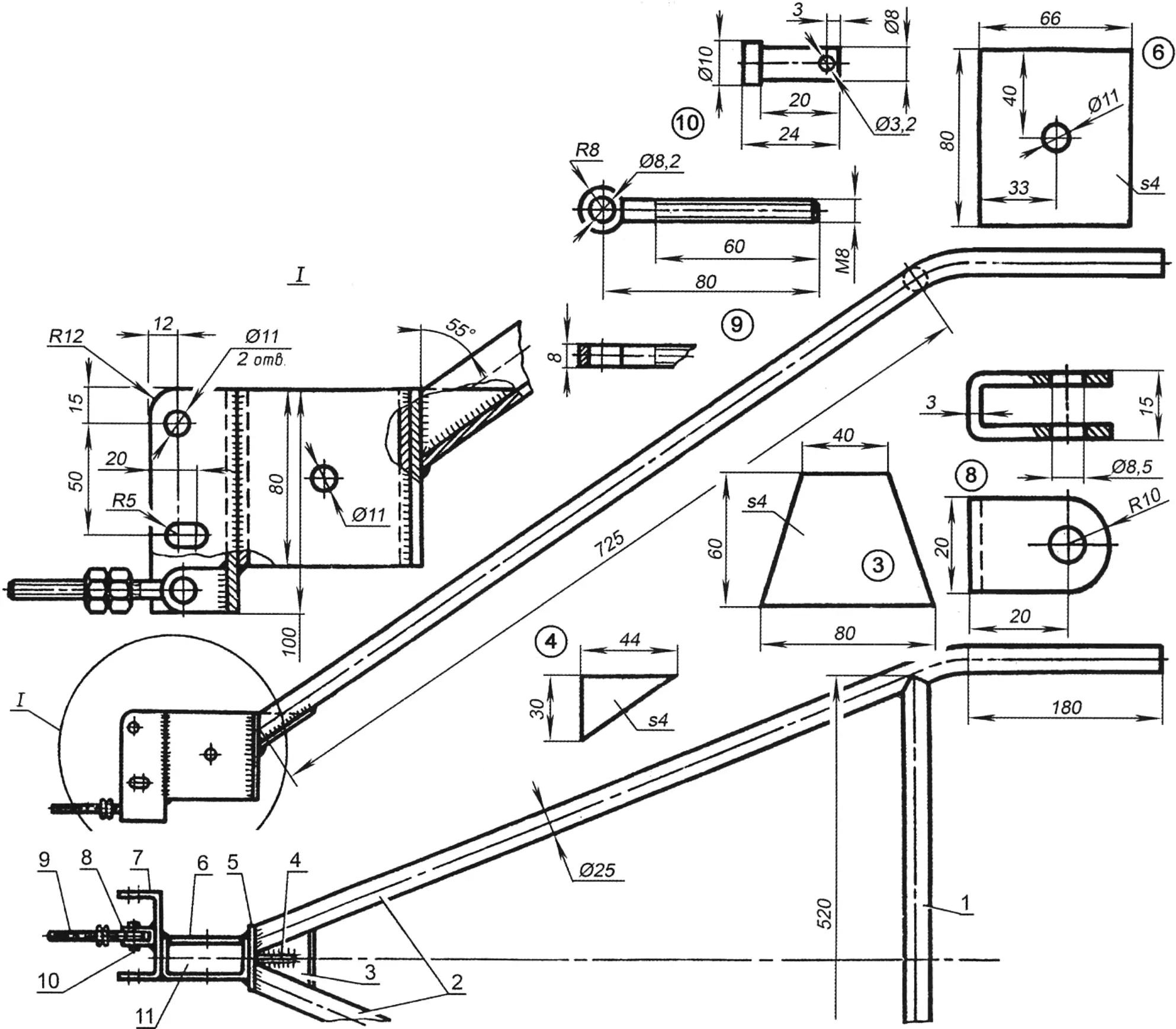
1 — crossbar; 2 — handles; 3 — gusset; 4 — stiffening rib; 5 — heel; 6 — clamp wall; 7 — bracket; 8 — fork; 9 — adjusting bolt with nut; 10 — bolt axis; 11 — holder clamp
Control handles are welded to the holder heel. To make the joint reliable, the weld area is reinforced with an overlay gusset and a stiffening rib. Plastic or rubber grips are fitted on the ends of the tubes. In front of them, M5x8 mm screws secure the clamps of the walk-behind tractor control levers: on the left — the clutch lever, on the right — the throttle. Cables from them go directly to the clutch and carburetor throttle of the engine. All these controls are from a scooter.
In conclusion, a few words about tillage implements. The chisel and cultivator-hiller are taken without modification from a scrapped cultivator. They are good for breaking up compacted soil crust and hilling potatoes. The plow, however, is homemade (Fig. 5). Its basis is the coulter of an ordinary mounted plow. A stop made of a sharpened steel plate is welded to it from below, and a deflector is welded to the moldboard from above. The additional elements help form the furrow correctly. To fasten this implement in the holder clamp, two holes are drilled in the coulter post. Using them, plowing depth can also be changed.
«Modelist-Constructor» No. 9’2012
Recommend to read
 NO WORSE THAN DIAMOND
The glass cutters with carbide rollers are widely used by home craftsmen. But those who work with glass often still prefer the diamond. And it's not just more sharpness and hardness of... THE ICE IS NOT TERRIBLE
If the sole of the Shoe to spread waterproof glue, and then not very thickly sprinkled with sand, you will feel on the ice, as on earth. R. ASTRAKHAN
