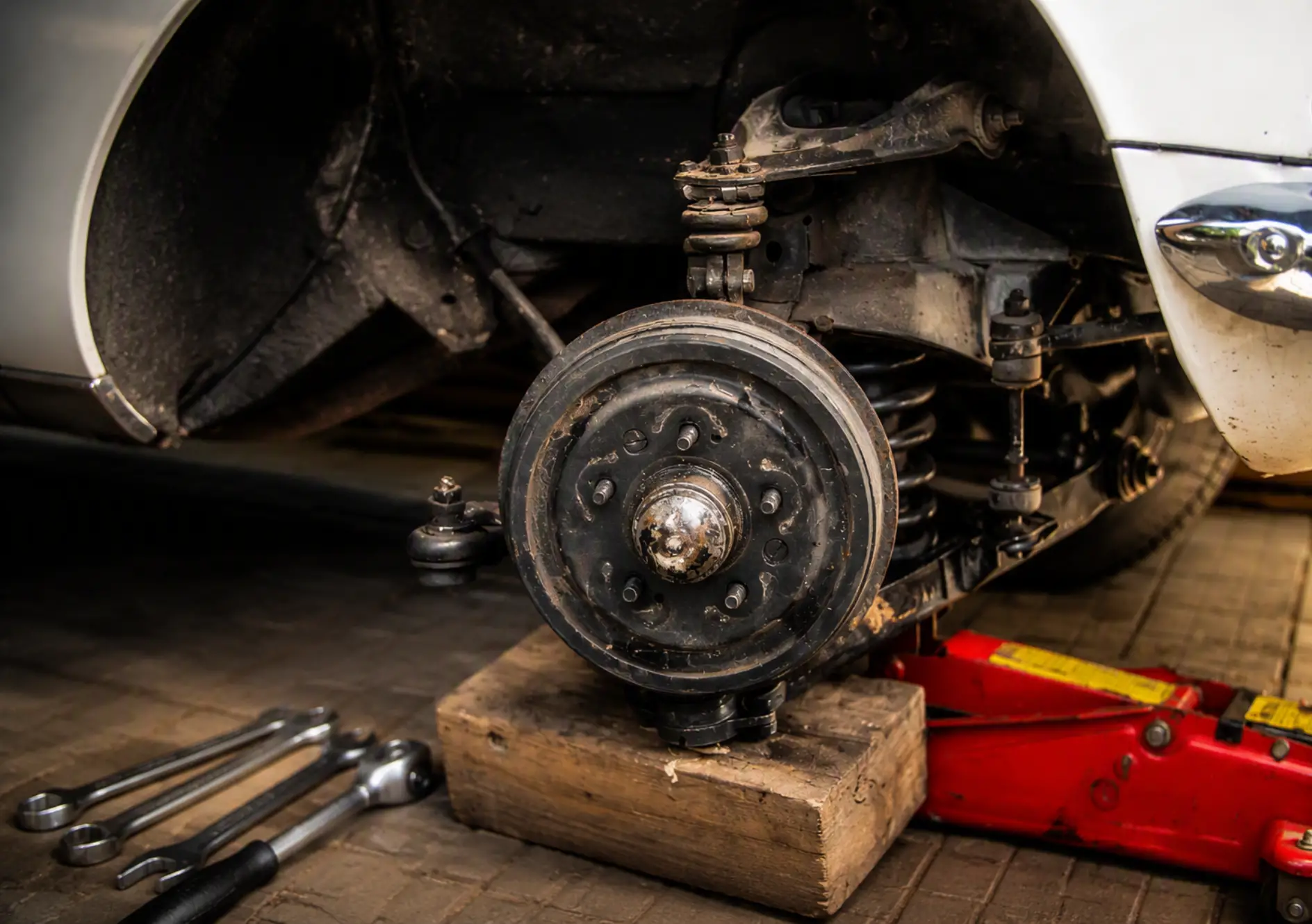
A car’s handling and tire wear, as is well known, depend primarily on the condition of the front suspension — the caster angles of the steering axes, as well as the camber and toe angles of the wheels. As a rule, all of these parameters are adjusted on special stands at service stations; however, even then the adjustment is far from always optimal for a particular car and particular operating conditions.
I managed to develop and implement a front-suspension adjustment scheme that is quite suitable for rear-wheel-drive cars of the VAZ or Moskvich type.
The adjustment scheme is shown in the figure. Before starting work, it is necessary to check the condition of the upper and lower ball joints, silent blocks, steering-rod joints, and the steering column, and if defects are found, they must be corrected. The car must be placed on a level surface over an inspection pit so that there is free access to the front wheels both from the inside and from the outside.
Technical instructions recommend adjusting the front axle under full static load (two people or 150 kg of load on the front and rear seats) and with a fully filled tank. It seems that this recommendation does not match the real operating conditions of a car. The fact is that a privately owned car spends the lion’s share of its time under a load of 1–2 people. Therefore, before adjusting the front axle, bags of gravel or sand, 25 kg each — three bags on each seat — should be evenly distributed on the front seats. If the tank is not fully filled, the fuel mass should be compensated with an additional load. Be sure to check the tire air pressure and, if necessary, bring it up to the specified value.
Checking and adjusting the front-suspension parameters is done in the following sequence:
1 — adjusting the position of the rear axle relative to the car body (axis) (dimensions OG and OV in the figure);
2 — adjusting the mutual position of the rear axle and the front suspension (dimensions AG and BV in the figure);
3 — adjusting the caster angles of the steering axes (View A);
4 — adjusting the wheel camber angles (View B);
5 — adjusting the wheel toe (dimensions L and I).
I note that the adjustments indicated in items 1 and 2 are performed only if suspension elements have been removed or replaced (for example, springs, leaf springs, longitudinal and transverse reaction rods) or after the car’s suspensions have taken a hard hit on a pothole that caused the car to “pull” to one side. These operations are carried out using a telescoping measuring bar made from curtain rods (with blades at its ends) by comparing dimensions OG and OV, AG and BV. If they differ from each other by more than 2 mm, adjustment is necessary. Points A, B, V, and G are the outermost symmetrical points on the front suspension and the rear axle; point O is the geometric center between points A and B.
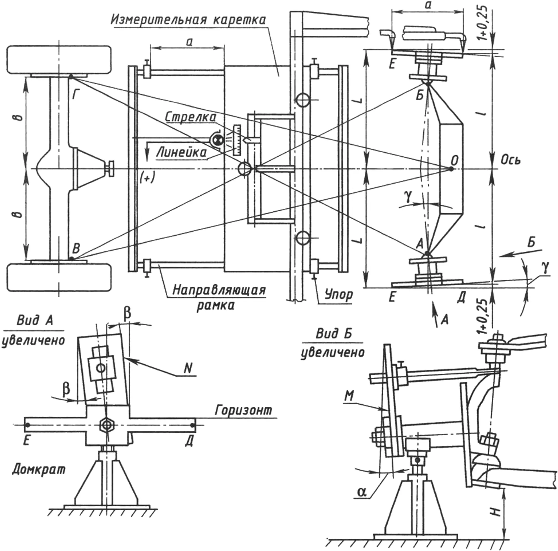
Before starting the adjustments indicated in items 3, 4, and 5, it is necessary to “pump” the front suspension — press down on the bumper with your hands several times so that the suspension arms take a mid position. After that, the values of H (View B) from the floor to the lower arm are measured on each side, and check stands (wooden or metal) of height H are made for each side. These stands may turn out to be unequal, which indicates different degrees of wear of the lower ball joints and tires.
The rear wheels are fixed on both sides with stops. After that, the front wheels and hubs are removed, and a fixture is mounted on the steering-knuckle axis, with jacks placed under them. By turning the jack screws, the lower arms are set relative to the floor to the value H (checked with the check stands). The front suspension is pumped again. Using a protractor with a measuring accuracy of 0°6″, the actual values of angles α and β are measured by alternately applying the protractor to planes M and N.
After that, we calculate how many adjusting shims and plates need to be removed or installed on each side, then install (or remove) them and, by remeasuring, determine the new (required) values of the indicated angles.
Wheel toe is checked using a measuring movable carriage that travels along guides aligned with the car’s axis.
The adjustment consists in changing the lengths of the steering rods. Before assembly, the wheels must be carefully balanced, after which a check run should be made on a level road section with no side wind.
Implementing the scheme considered here is more labor-intensive than others, but it is more accurate and, as a result, you will significantly reduce tire wear and improve the car’s handling.
“Modelist-Konstruktor” No. 5’2007, V. TOKMANENKO, mechanical engineer, Kropyvnytskyi
Recommend to read
 NOT FLOUR, AND THE CURRENT
Live in the taiga wilderness, starved (fuel for the diesel generator running out) energy rations. And next carelessly rushing river. Natural, so to speak, a source of energy, what... TO MEASURE, NOT MEASURING
If you have a lot of time to measure the volume of the same liquid or granular materials, make the appropriate mark on the measuring circle, glued at the right level strips of adhesive...
