Less and less often you’ll see nimble mopeds on our roads. And this is not surprising: the main manufacturers, by the will of fate, ended up abroad — in Latvia and Ukraine. So everything that is still sold from this range in specialized stores today are foreign-made models. Accordingly, the price…
Moreover, fickle motorcycle fashion offers consumers more convenient, more modern machines of the same class — scooters. Miniature motor scooters with a 50cc engine, equipped with automatic transmission and starter, reach speeds of up to 80 km/h, providing comfort that the owner of a “Riga” or “Karpaty” could never have dreamed of.
But why spend money on fashionable scooters if you can convert an old moped into a more modern machine of the “city-bike” class? The machine, the design of which we want to introduce you to, is distinguished by compactness, reliability, and increased comfort, fully justifying its belonging to the family of urban mini-mopeds.
It should be noted that the city-bike was created based on the “Karpaty” moped (in principle, any other moped or moped with a Sh-58, Sh-62, or V-50 engine would work). In particular, from it were used the front fork with steering column, rear swingarm fork with shock absorbers, seat, V-50 engine, and various small parts like headlight, control handles, and taillight. The city-bike’s wheels are from a Riga-produced mini-moped.
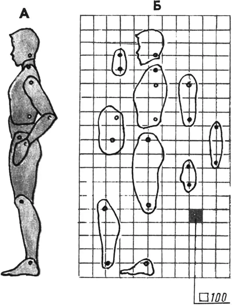
The city-bike was designed using flat models. For this, on cardboard in a convenient working scale of 1:2, silhouettes of all ready-made units and assemblies were drawn — engine, front and rear forks, shock absorber, headlight, etc. Of course, an articulated driver silhouette was also required.
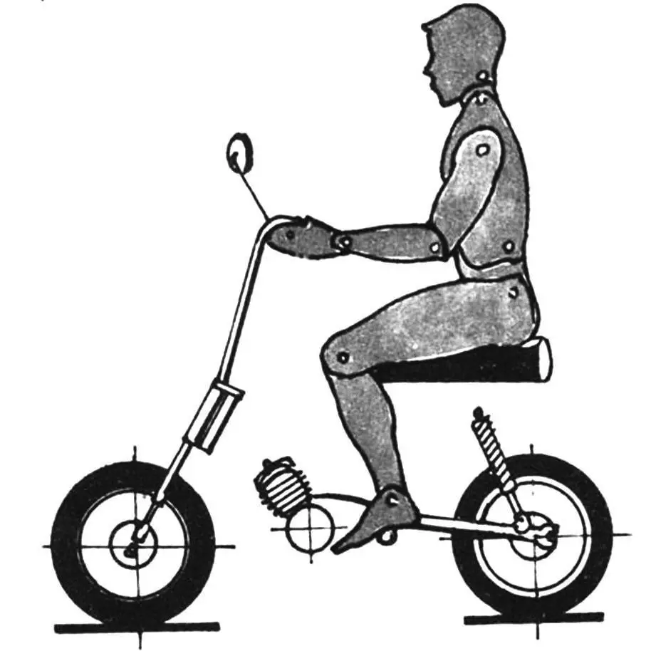
The layout development began with placing an articulated human silhouette on the drawing plane in a position convenient for riding a moped. Next, a seat and footrests were positioned under the “driver,” and handlebar grips under his arms. From the position of the grips, the coordinates of the front fork and, accordingly, the front wheel were determined, after which it was easy, having set the wheelbase (in this case 1060 mm), to determine the coordinates of the center of the rear wheel, rear fork, and shock absorber.
The next stage of work is the placement of the power unit and fuel tank. The most rational position of the engine on the frame is such that the center of the engine’s drive sprocket, the swingarm fork axis, and the rear wheel axis are on one straight line — in this case, when the rear fork swings, the drive chain tension variations are minimal. Thus, the engine’s position on the frame was also determined unambiguously. And placing a fuel tank with a capacity of about 5 liters on the moped was not difficult: the only more or less suitable place for it is under the driver’s seat.
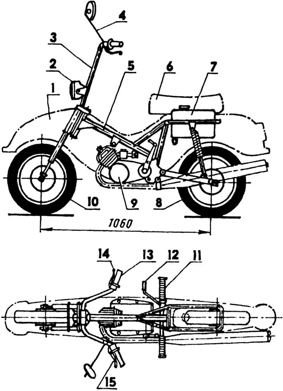
1 — fairing; 2 — headlight; 3 — handlebar; 4 — mirror; 5 — frame; 6 — driver’s seat; 7 — fuel tank; 8 — rear wheel; 9 — V-50 engine; 10 — front wheel; 11 — footrest; 12 — brake pedal; 13 — carburetor throttle control handle (“gas”); 14 — brake lever; 15 — clutch control lever.
Next came what required real design work from the layout engineer — combining all the moped’s units and assemblies with a rigid, strong, and light frame. The simplest version is in the drawing. This is a backbone-type frame made of 34×34 mm square steel tubes and 20 mm diameter round ones, with engine mounting nodes (front and rear) and shock absorber mounting brackets.
The city-bike construction began with assembling the flat part of the frame, consisting of the backbone and seat beams and steering column. These elements were joined on a particle board, on which the city-bike frame was previously drawn. Such a template allowed fitting the frame elements and controlling its geometry after welding.
The next stage is the manufacture and welding of the seat part made of 20 mm diameter steel tube to the frame. The tube was bent using standard technology: it was filled with dry sand, the bend location was heated with a blowtorch, after which the workpiece was twisted around a suitable mandrel (steel tube) with a diameter of 130 mm.
From 3 mm thick steel sheet, the cheeks of the engine mounting nodes and shock absorber brackets were cut. As can be seen from the drawing, the swingarm fork hinge and footrest mounting bushing are cut into the cheeks of the rear engine mounting node. Both the hinge and bushing are tube segments (bushing — 20×2 mm diameter, hinge — 22×2 mm). After fixing the rear node cheeks on the frame, the engine was installed in them, after which the front engine mounting node cheeks were fitted in place and tack-welded. Then the engine was removed from the frame, and the cheeks were finally welded. Similarly, the shock absorber bracket cheeks were welded to the seat part of the frame.
To check the correctness of the frame assembly, the front and rear wheels were mounted on it, then the frame was turned over, and the parallelism of the wheels was checked in this position.
The moped’s footrests are a 16 mm diameter steel rod, fixed in its designated bushing using a pair of electric rivets. Rubber covers from the moped are stretched over the footrests. On the right side, a brake pedal bent from a 10 mm diameter steel rod, which is welded to a steel bushing, is mounted. On this same bushing, a brake lever consisting of two 2.5 mm thick steel plates is welded, and on the frame bushing, a stop for the Bowden brake cable sheath is welded.
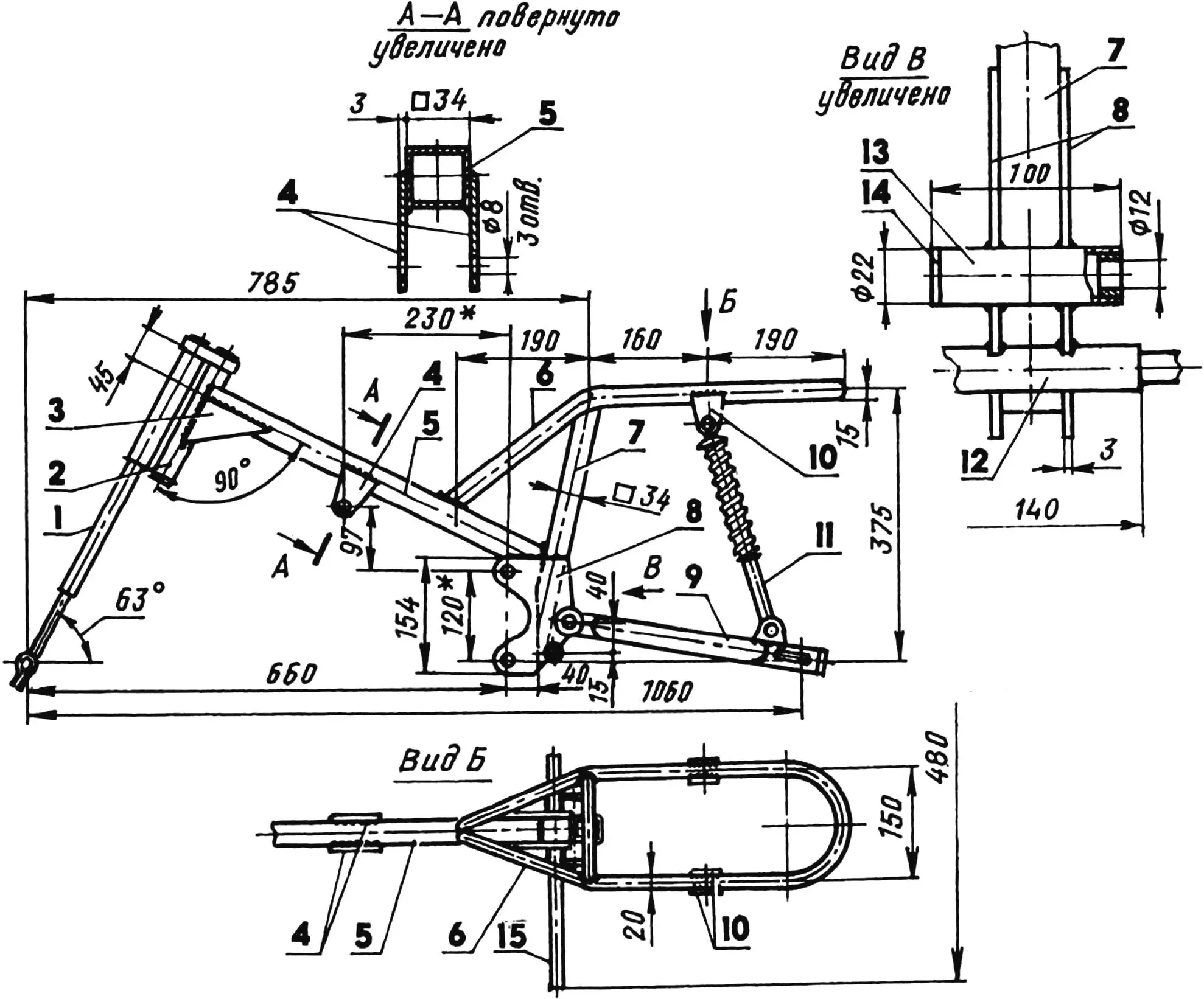
1 — front fork (from “Karpaty” moped); 2 — steering column (from “Karpaty” moped); 3 — gusset (steel sheet s2.5, 2 pcs.); 4 — front engine mounting node cheeks (steel sheet s3); 5 — backbone beam (34×34 steel tube); 6 — seat part of frame (20×2.5 steel tube); 7 — seat beam (34×34 steel tube); 8 — rear engine mounting node cheeks (steel sheet s3); 9 — swingarm fork, rear (from “Karpaty” moped); 10 — left shock absorber mounting bracket cheeks (steel sheet s3); 11 — left shock absorber; 12 — footrest mounting bushing (22×3 steel tube); 13 — swingarm fork hinge body (22×2 steel tube); 14 — bushing (textolite or fluoroplastic); 15 — footrest (Ø16 steel rod).
Dimensions marked with * are determined during assembly.
The city-bike’s fuel tank is from a suitable 5-liter canister. For fixing the canister on the seat part of the frame, cradles made of 30×2 mm cross-section steel strip are provided. In the lower part of the canister, a standard motorcycle tap with filter-sediment bowl is located. In the fuel tank cap, a drain hole with a simple valve made of thin sheet oil-and-gasoline-resistant rubber is provided, preventing fuel leakage in case of accidental moped fall.
The city-bike’s handlebar is from a Riga-produced mini-moped, however, it’s not that difficult to make it yourself from a 22×1.5 mm diameter steel tube. The headlight is fixed in brackets welded to the handlebar.
After mounting the seat, engine, and exhaust system on the city-bike’s running gear, the machine was adjusted and tested on the road.
Last, a lightweight fiberglass fairing was made, giving the moped the right to be called a city-bike. The fairing was designed for laying up from fiberglass cloth over a mold, and this allowed giving it a somewhat unusual shape.
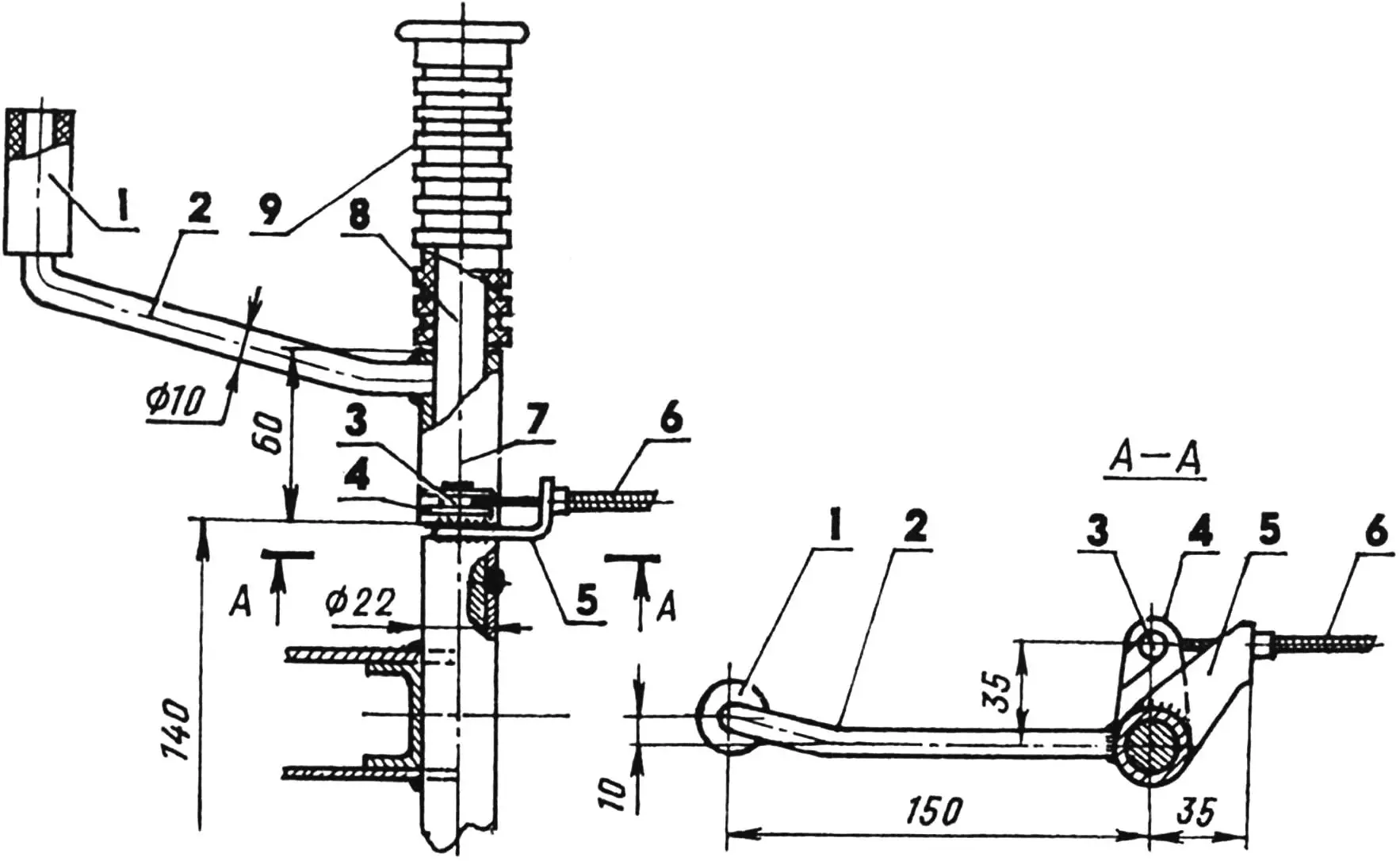
1 — pedal sheath (rubber hose segment); 2 — brake pedal (Ø 10 steel rod); 3 — brake cable ferrule; 4 — brake lever (steel sheet s3); 5 — stop (steel sheet s4); 6 — brake cable sheath, Bowden; 7 — brake pedal bushing (24×4 steel tube); 8 — footrest (Ø 16 steel rod); 9 — footrest cover.
The mold was assembled from construction foam blocks. To make the fairing symmetrical, the following method of mold processing was used. First, only its left side was finished, puttied with plasticine, and several templates (from thick cardboard) were taken from the mold. According to these templates, the right side of the mold was processed. To complete the work, a thin polyethylene film was rolled onto the plasticine surface, ensuring removal of the shell from the mold after laying up.
Before laying up, the wax coating was removed from the fiberglass cloth, for which the fiberglass was soaked in gasoline, but it can also be burned off — evenly draw a strip of fiberglass over a heated electric hotplate.
Epoxy resin was used as the binder for laying up. To obtain a shell of the required thickness, it was necessary to apply five layers of fiberglass cloth to the mold.
After the resin polymerization, the shell was removed from the mold, puttied and sanded, then coated with primer and automotive enamel. The finished fairing was fixed to the city-bike frame at four points: to the upper bridge of the front fork, to the seat part of the frame and rear engine mounting node using threaded bushings fixed on it.
«Modelist-Konstruktor» No. 9’99, I. KARAMYSHEV, engineer
Recommend to read
 HANGER FOR BATH
I bought a plastic baby bath. Comfortable, beautiful, but where is her store! Decided it was better just to hang on the wall in the bathroom horizontally. This is enough for two... HONDA S2000
Scale model 1:18. Honda S2000 — the car rear-wheel drive front-engined and rear wheel drive Roadster with equal weight distribution on front and rear axle, manufactured by Honda....
