A sharp and properly sharpened tool has always been an indicator of its owner’s professionalism. However, the master’s ability to bring their production tools into working condition is no less important. But quality tool sharpening with a simple whetstone or electric grinder is not only time-consuming but also difficult. They are being replaced by more productive devices and even machines of industrial or homemade manufacture.
An example is the universal sharpening machine, developed by our magazine’s regular author Vladimir Ivanovich Petrov, an amateur designer.
In this taiga region, where a significant portion of the population is professionally or for household needs engaged in woodworking and where almost every third home has a chainsaw, life shows: at least in a logging workshop, such or a similar sharpening machine is simply necessary.
The universal sharpening machine, or, briefly, USM (Universal Sharpening Machine), is designed for a wide variety of metalworking operations. It can, of course, also serve as a simple electric grinder. However, it also has many other capabilities. It can perform, for example, not only conventional sharpening of locksmith and carpentry tools, including drills, wood and metal cutters, but also restoration at strictly specified angles of the teeth of saw chains of brands PTSU2-9.3, PTSU-10.26, and PCP-15, used in gasoline and electric saws. The machine is also suitable for cutting metals with simple and diamond abrasive wheels, wood processing (cross-cutting, longitudinal sawing, tenon cutting, etc.).
The listed operations are far from exhausting the list of work performed on the universal machine.
Such a wide range of capabilities is achieved through the design features of the machine and the devices attached to it. In addition, the USM has small dimensions, which allows it to be used even in cramped workshops, and easily disassembles into three parts.
Among the undoubted additional advantages of the machine, it should also be noted that the technical maintenance of the device is minimal. Practically, it mainly comes down to monitoring the tension of the V-belt and infrequent application of thick consistency lubricant (grease) to the vertical axis of rotation of the power bracket.
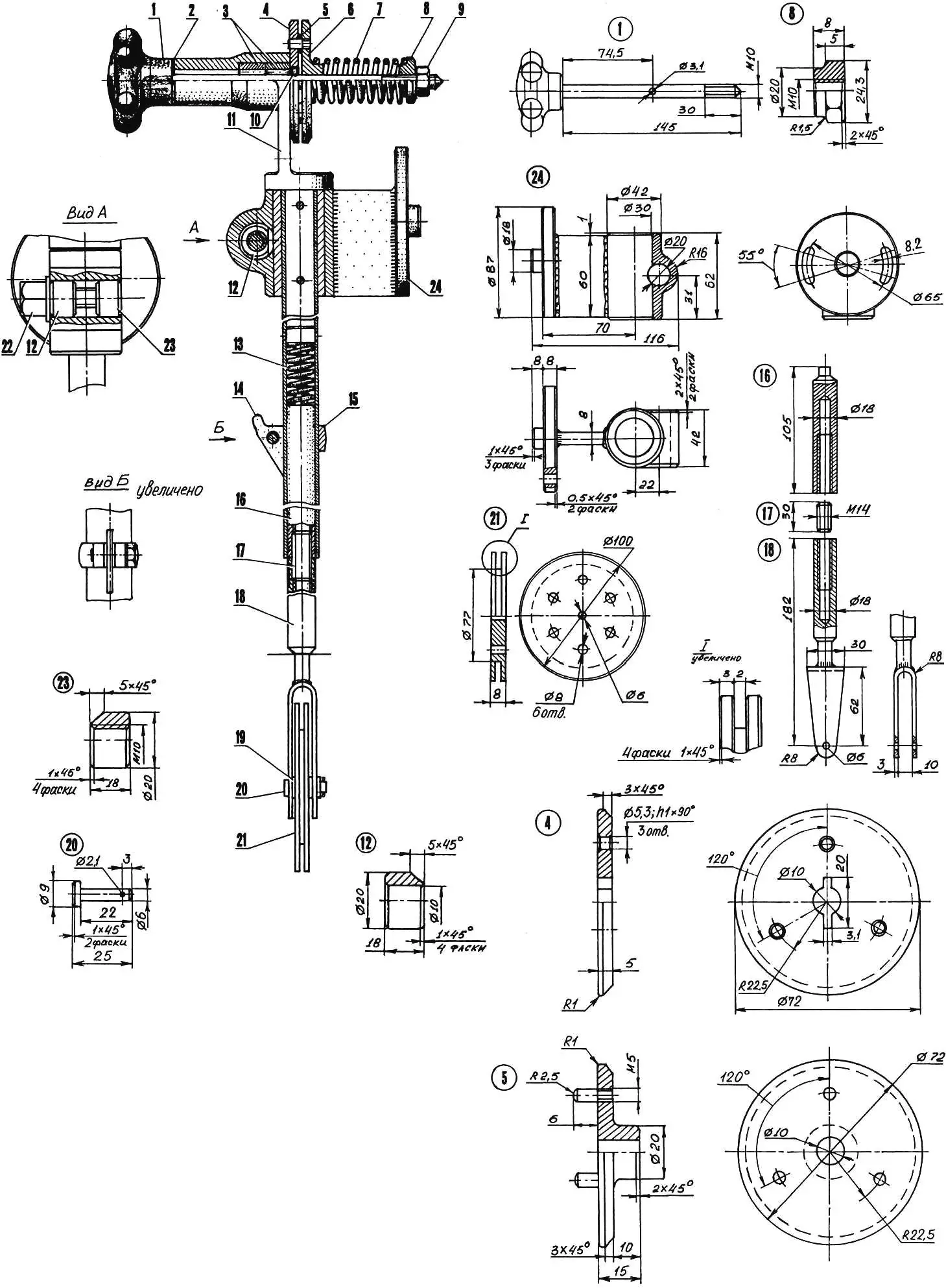
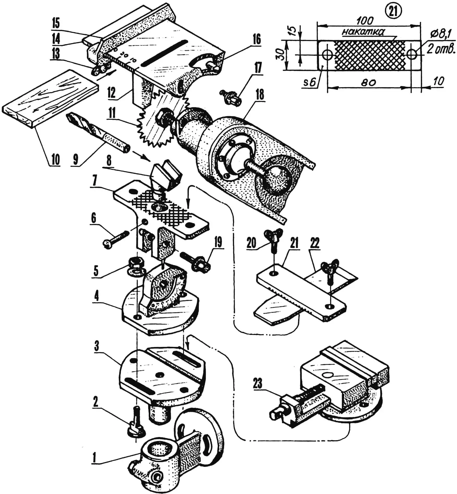
Before moving on to the design features of the machine, I would like to note the following. It seems to me that the reader will find it more convenient to understand the device as a whole by first examining it by individual components of the machine. Therefore, they are first presented in the drawings as a scatter of parts—a kind of catalog of units—and then they will be considered in detail in assembly.
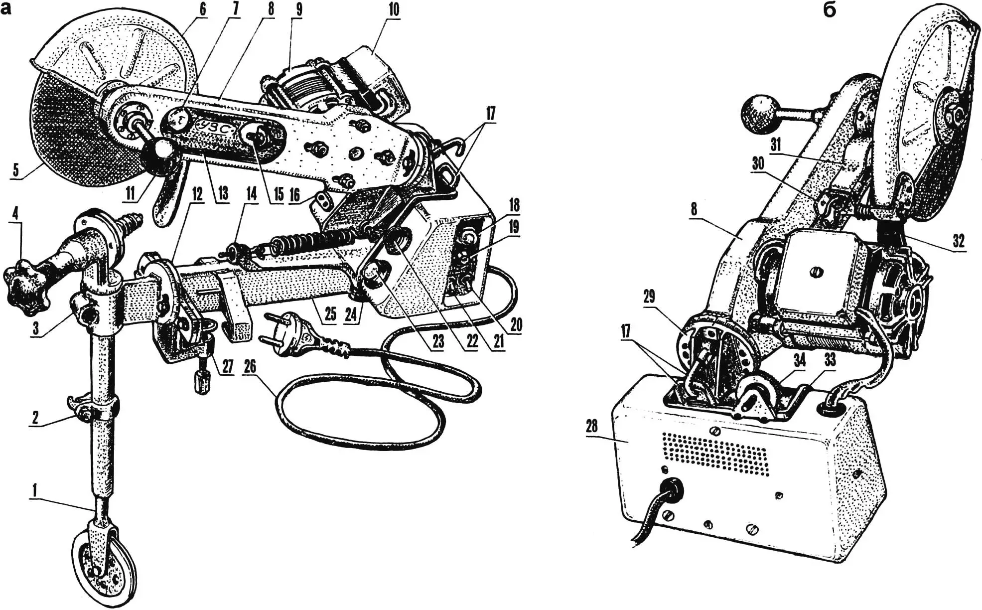
1 — attachment for sharpening saw chains; 2 — clamp with hook for saw chain remover; 3 — swivel console of attachment; 4 — handle for rotating saw chain in device; 5 — abrasive wheel; 6 — protective guard; 7 — local lighting lamp; 8—pendulum housing; 9 — electric motor; 10 — distribution box; 11 — abrasive wheel feed handle; 12 — intermediate flange; 13 — V-belt (type A, L850); 14 — power bracket with pendulum balancing mechanism; 15 — belt tension mechanism; 16 — electrical outlet; 17 — pendulum locking mechanism parts (on a — in non-working position, on b — in working position); 18 — indicator lamp; 19 — electrical fuse housing; 20 — electric motor reverse toggle switch; 21 — local lighting lamp toggle switch; 22 — “start” button; 23 — “stop” button; 24 — rubber pad; 25 — base; 26 — electrical cord with plug; 27 — machine clamping clamp; 28 — control panel; 29 — pendulum hinge; 30 — combined bracket; 31 — local lighting lamp reflector; 32 — protective rubber apron; 33 — power bracket; 34 — mechanism for adjusting pendulum position in non-working position
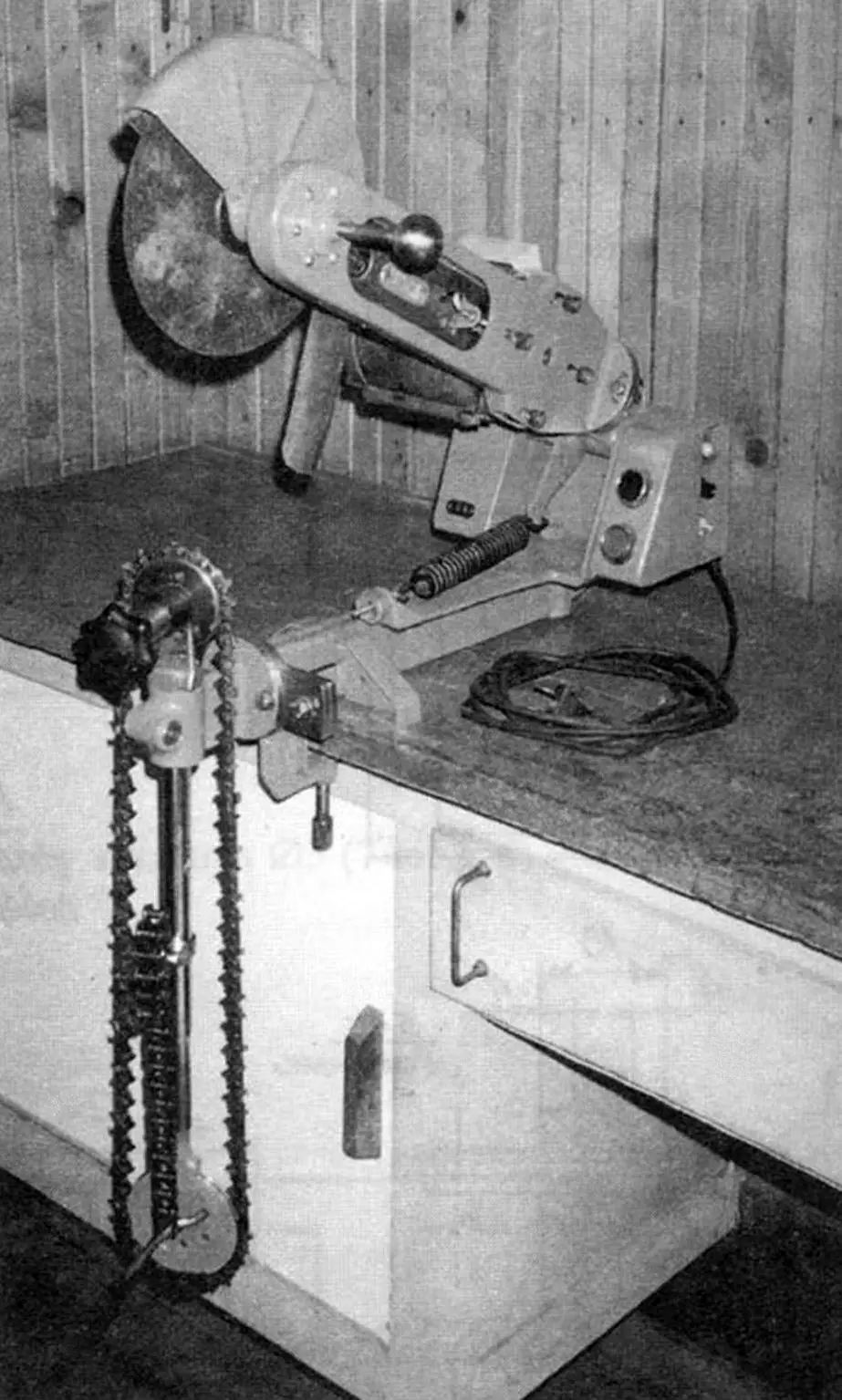
The USM (fig. 1) consists of a pendulum with a motor installed on it, a pendulum hinge, a box-type power bracket, a control panel, which houses almost all the machine’s electrical equipment, and a base, rigidly fixed to the workbench with a clamp (fig.5). Such a large number of parts required an appropriate approach to their layout, which would ensure not only reliable operability of the structure but also achieve its compactness and convenience for performing various operations.
Therefore, for example, the longitudinal axis of the pendulum, when viewed from the clamp side, is shifted to the right relative to the longitudinal axis of the base. This solution helped to more evenly distribute the mass of the structure, increase its stability, and reduce dimensions.
A similar approach was chosen when solving such a task as setting the angle of vertical “aiming” of the pendulum: it is also selected using the simplest mechanism, consisting of a round knurled nut and an adjustment screw. They are installed on the rear wall of the power bracket. Thanks to the small pitch of the threaded displacement, they can also be used for precise feed of the abrasive wheel when sharpening carpentry and locksmith tools.
In the non-working position, the pendulum is held in the air by elements of another simple device—the locking mechanism (fig.1). It consists of a spring-loaded hook located on the pendulum hinge and a bracket fixed on the power bracket: the hook enters and engages with it when the pendulum is suspended.
The welded box-type pendulum housing (fig.6) has sufficient rigidity, which made it possible to install the electric motor directly on it without additional brackets. At the same time, the housing serves as a guard for the V-belt drive.
Windows are cut in the housing along its sides, performing a dual role: they reduce mass and also allow visual monitoring of V-belt tension. An additional lower window is also cut: through it, small foreign bodies that accidentally enter the housing during mechanism operation are automatically removed.
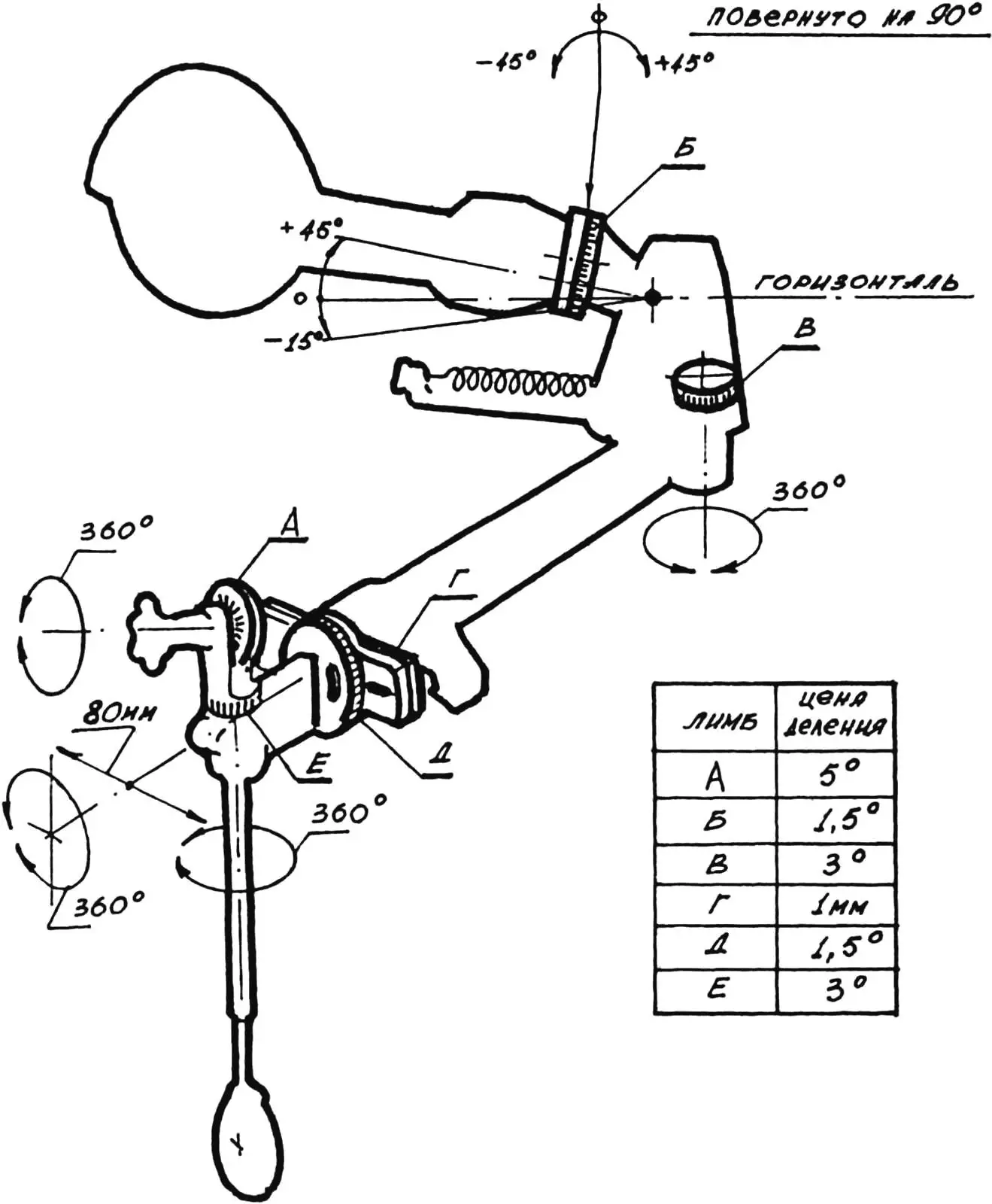
A flange with two arc slots for screws is welded to the rear of the housing, with which it is attached to the flange of the pendulum hinge. These screws set the angle of lateral tilt of the housing: smoothly—by rotating the housing within the length of the arc slots, or stepwise—by repositioning the screws into other threaded holes of the pendulum hinge flange. A limb with a division value of 1.5° is marked along the entire circumference of the latter for reading the required angle.
1 — rib (steel, sheet s5, 2 pcs.); 2 — flange; 3 — lever (steel, sheet s5); 4 — housing; 5 — stop (steel, sheet s6); 6 — center
The pendulum hinge (fig. 4, 6) is an assembly unit. It is made in the form of a bushing with two bearings inside and a lever, stop, flange, and gussets welded on the outside. In the vertical plane, it rotates on an axis, which is a shaped bolt with two bearing seat journals. The threaded end of the axis is screwed into the right hole of the power bracket and fixed with a lock nut (fig. 5).
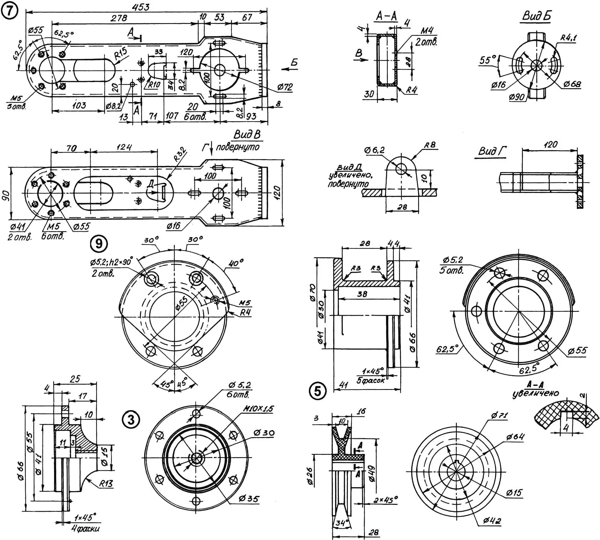
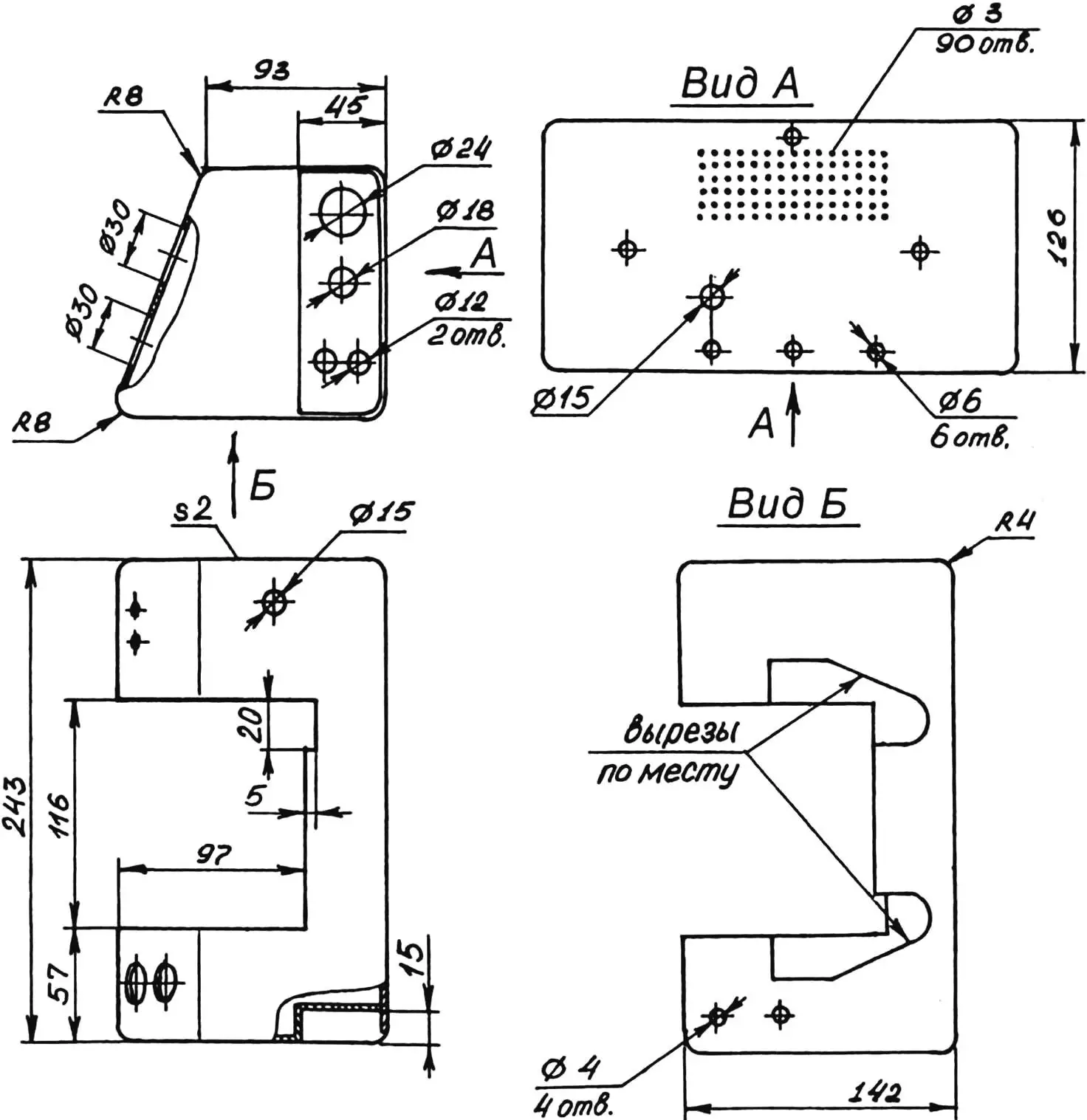
The power bracket (fig. 7) is welded in the form of a half-box from steel sheets of different thicknesses. On its rear wall are located, as already mentioned, lugs for the adjustment screw and knurled nut of the vertical “aiming” mechanism of the pendulum, as well as a bracket of its locking mechanism in the non-working position.
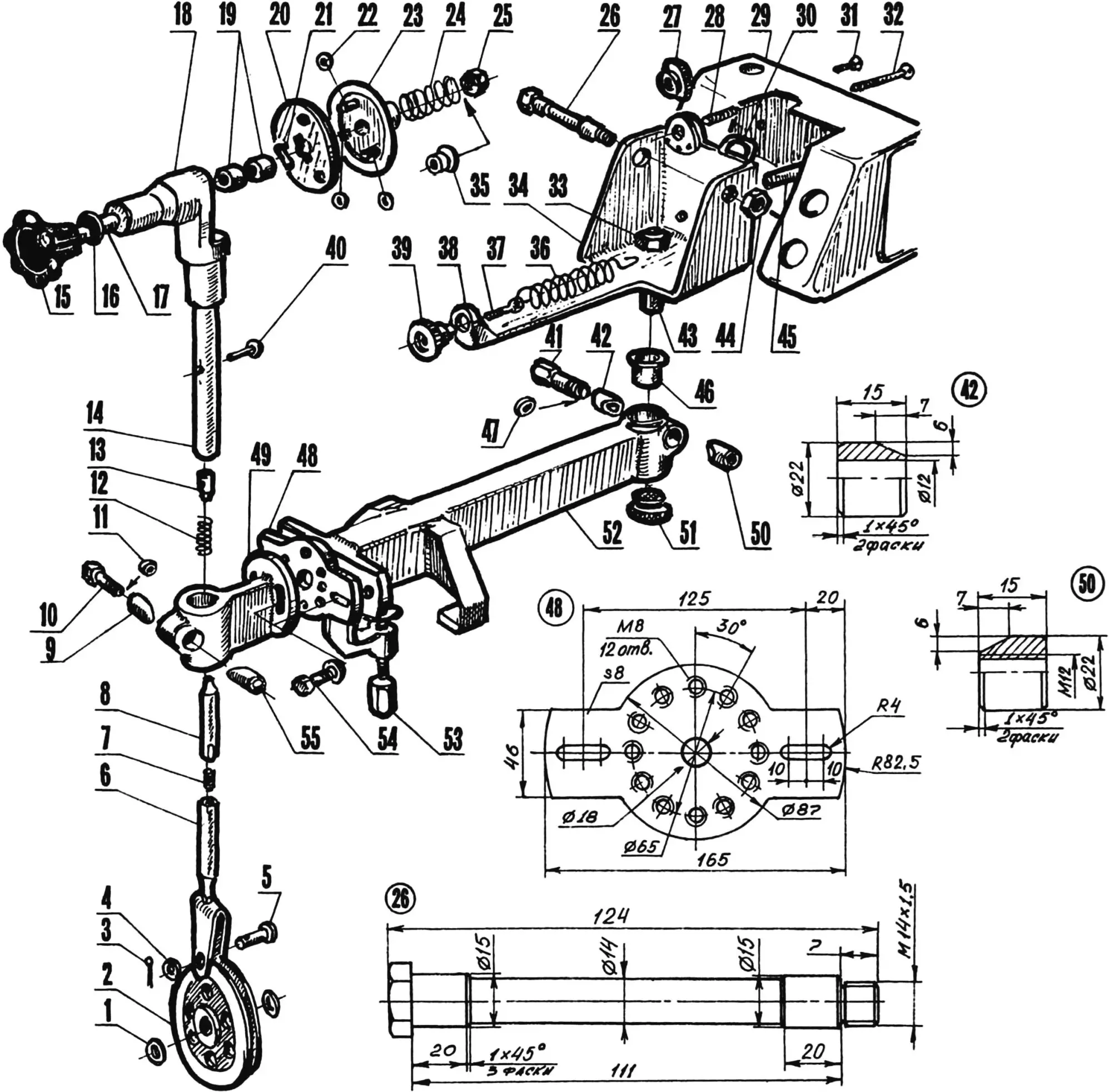
1 — lower spacer washer (2 pcs.); 2 — guide pulley; 3 — cotter pin; 4, 11, 47 — washers; 5 — pin; 6 — main rod; 7 — stud M14; 8 — additional rod; 9, 42 — wedge-bushings; 10 — bolt M10; 12, 24 — compression springs; 13 — internal spring stop; 14 — support tube; 15 — handle; 16 — PTFE washer; 17 — axis-bolt M10; 18 — bracket; 19 — roller bearings; 20 — drive flange; 21 — pin; 22 — upper spacer washer (3 pcs.); 23 — driven flange; 25 — adjustment nut M10; 26 — pendulum hinge axis; 27, 28 — nut and screw M8 of mechanism for adjusting pendulum position in non-working position; 29 — control panel housing; 30 — pendulum locking mechanism bracket; 31, 32 — control panel housing mounting screws; 33, 44 — nuts M14x1.5; 34 — power bracket; 35 — thrust bushing-nut; 36, 37, 39 — spring, loop bolt and knurled nut M6 of pendulum balancing mechanism; 38 — machine console; 40 — rivet; 41 — bolt M12; 43 — power bracket axis; 45 — stand (2 pcs.); 46 — PTFE bushing; 48 — intermediate flange; 49 — swivel console; 50, 55 — wedge-nuts; 51 — rubber pad; 52 — base; 53 — clamp screw; 54 — screw M8 with split washer (2 comp.)
The front of the power bracket has an extended console with a bent end reinforced with gussets. At the end is a knurled nut, the bushing of which is flared after insertion into the hole so it doesn’t fall out. This nut, together with the loop bolt and spring, make up the pendulum balancing mechanism.
A hole with M14x1.5 thread is provided in the bottom of the half-box, into which the threaded end of the vertical axis, intended for rotating the power bracket, is screwed and locked with a nut. A circular scale with a division value of 3° is also located here—the angle of this rotation is measured by it.
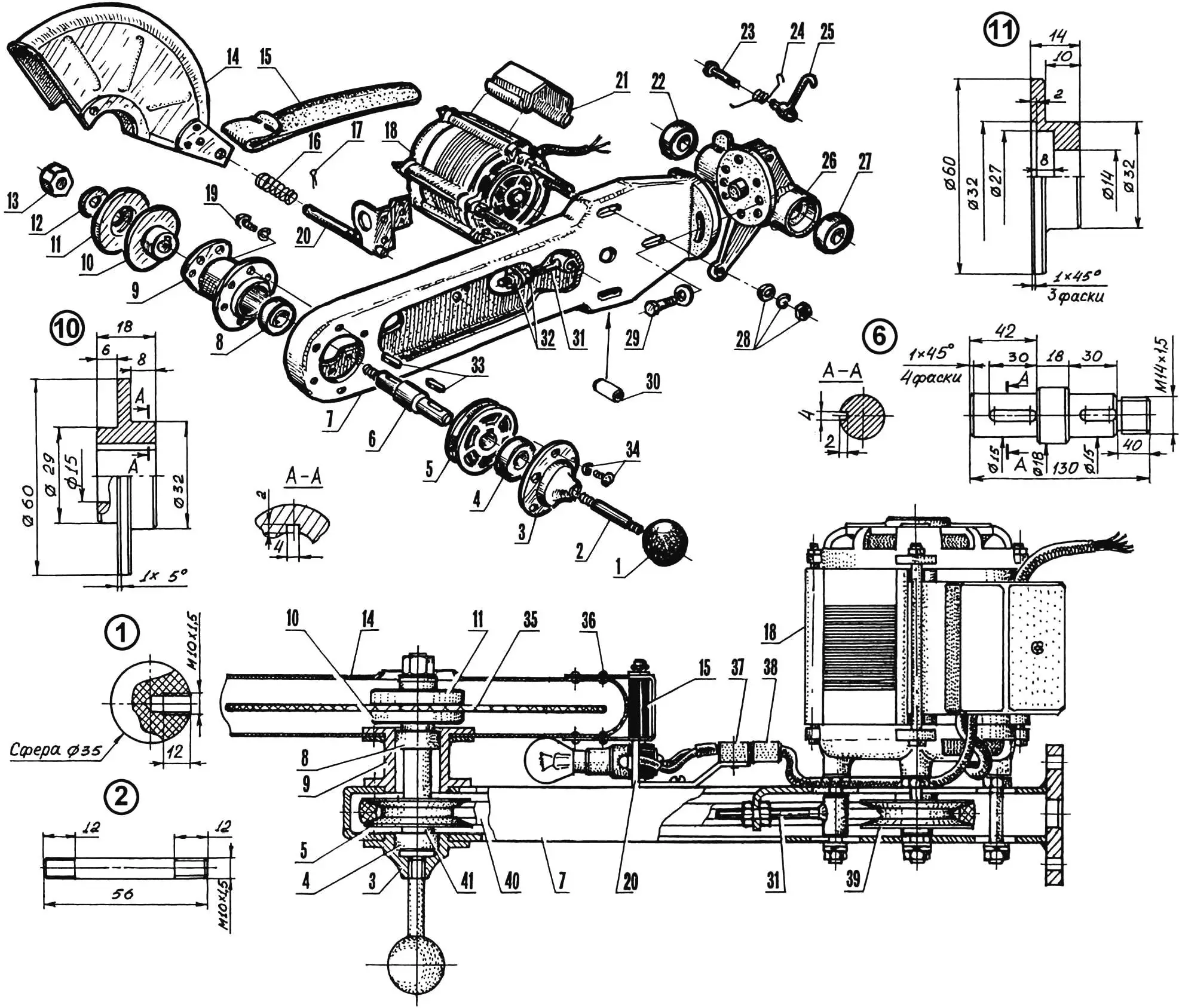
1 — ball handle; 2 — lever; 3 — right bearing housing; 4, 8, 22, 27 — bearings 6202; 5 — driven pulley; 6 — working shaft; 7 — pendulum housing (steel, sheet s8, sheet s4); 9 — left bearing housing; 10 — hub; 11 — clamping flange; 12 — washer; 13 — nut M14x1.5; 14 — protective guard; 15 — protective rubber apron; 16 — compression spring; 17 — cotter pin; 18 — electric motor; 19 — screw M5 with split washer; 20 — combined bracket; 21 — distribution box bracket; 23 — screw M6; 24 — torsion spring; 25 — pendulum locking mechanism hook; 26 — pendulum hinge; 28 — nut M8 with split and flat washers (3 comp.); 29 — screw M8 with flat washer; 30 — spacer bushing (3 pcs.); 31, 32 — bolt, nut and lock nut M5 of belt tension mechanism; 33 — prismatic keys; 34 — screw M5 with split washer (6 comp.); 35 — abrasive wheel; 36 — rivet; 37, 38 — electrical connector plug and socket; 39 — drive pulley; 40 — V-belt; 41 — spacer washer
The control panel housing, welded from sheet steel, is attached to the rear wall of the half-box with three M6 screws.
In the right side of the panel is a niche that protects from mechanical damage the socket with indicator lamp, holder with fuse, and toggle switches for power on and electric motor reverse.
1 — side (steel, sheet s5); 2 — console (steel, sheet s5); 3 — axis (steel, rod Ø25); 4 — gusset (steel, sheet s2, 2 pcs.); 5 — platform (steel, sheet s10); 6 — pendulum locking mechanism bracket (steel, rod Ø4); 7, 8 — loop bolt and knurled nut M6 of pendulum balancing mechanism; 9, 10 — nut and screw M8 of mechanism for adjusting pendulum position in non-working position; 11 — loop (steel, sheet s4, 2 pcs.); 12 — rivet (steel, Ø4, 3 pcs.)
1 — electrical connector plug; 2 — combined bracket; 3 — insulating bushing; 4 — electrical socket; 5 — electric lamp; 6 — reflector
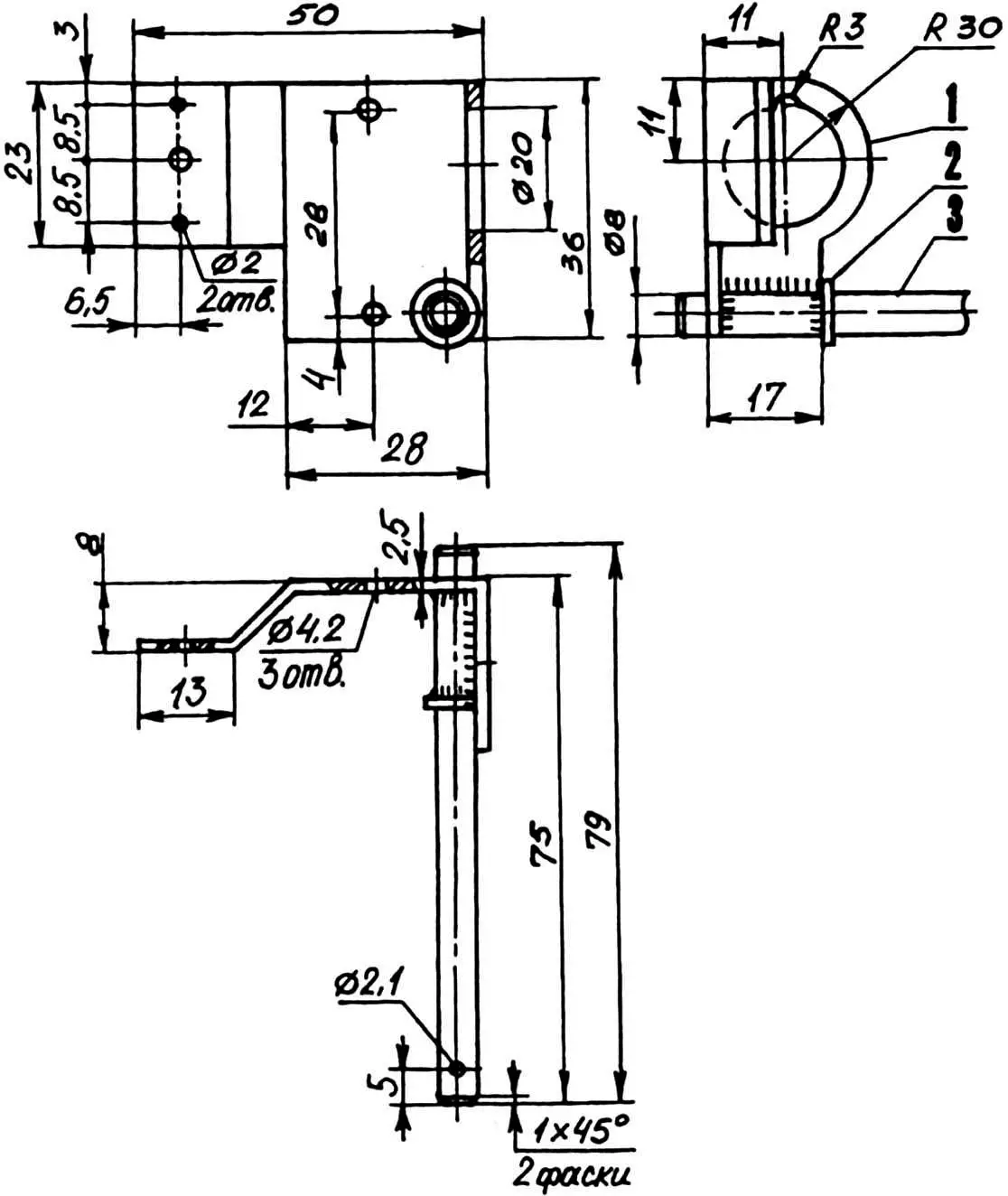
1 — clamp plate; 2 — clamp screw M8; 3 — clamp (steel, sheet s8, rod Ø24); 4 — transverse plate (steel, sheet s8); 5 — side foot (steel, sheet s5, 2 pcs.); 6 — wall (steel, sheet s3, 2 pcs.); 7 — housing (steel, tube 60x30x3); 8 — insert (PTFE); 9 — bushing (steel)
The USM base (fig. 9) is made from a section of rectangular tube. A transverse plate with different holes is welded to its front end: the central threaded one is for mounting interchangeable attachments, six side ones are for stepwise adjustment of the intermediate flange position.
On the workbench, the base rests on side feet and a rubber pad and is securely held by a screw clamp. A bushing with a PTFE insert for the vertical axis of rotation of the power bracket is also welded into the base. The specified position of the latter is easily fixed, since the bushing is equipped with a special wedge clamp for its axis.
1 — nut; 2 — washer; 3 — clamping flange; 4 — abrasive wheel; 5 — paronite washer (2 pcs.); 6 — hub; 7 — prismatic key; 8 — machine working shaft
The intermediate flange is attached to the front of the base. It has threaded and slotted holes: the first are for screws mounting the swivel console of the attachment intended for sharpening saw chains, the second are for screws for stepwise adjustment of the intermediate flange position. The flange tilt angle can be assessed by the limb with a division value of 1.5° marked on top of its edge.
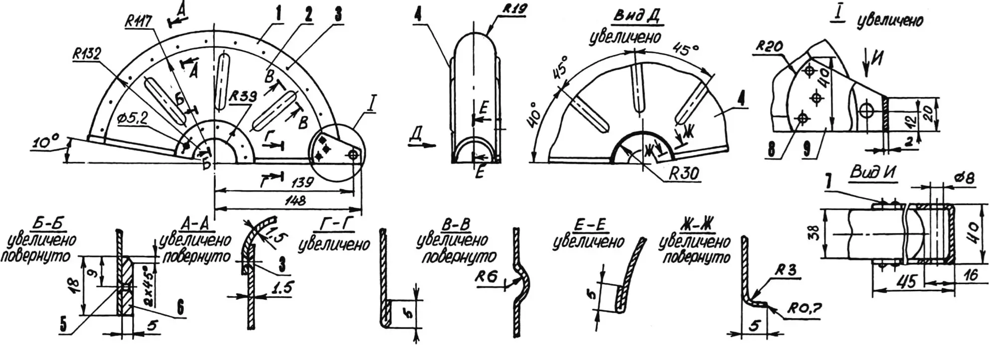
1 — arch (steel, sheet s1.5); 2, 4 — side walls (steel, sheet s1.5); 3 — rivet Ø2 (22 pcs.); 5 — rivet Ø3 (7 pcs.); 6 — overlay (steel, sheet s5); 7, 8 — rivet Ø3 (6 pcs.); 9 — bracket (steel, sheet s2)
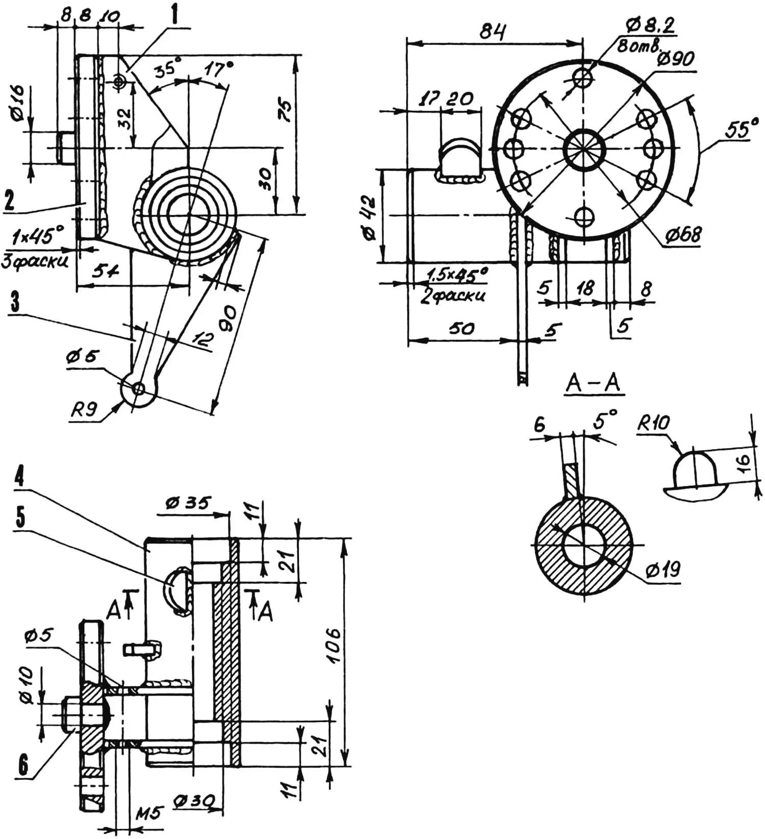
The most commonly used tool of the USM is the abrasive wheel (fig. 10). In working condition, it is reliably covered by a protective guard (fig. 11), which rests with its cutout on the left bearing housing of the working shaft, which is at the end of the pendulum, and is attached to the flange of this housing with just one M6 screw. In case of replacing the abrasive wheel, the screw is easily unscrewed, the guard is swung back on the swivel axis until it contacts the electric motor, thereby opening free access to the working shaft.
The guard has a rubber apron that protects the control panel from being bombarded with sawdust and abrasive wheel particles.
1 — shaped plate (steel, sheet s2.5); 2 — support washer for compression spring; 3 — protective guard axis (steel, rod Ø5)
An electric lamp on a combined bracket (fig. 8, 12) is installed in the gap between the guard and the pendulum. This is the most convenient location: the lamp, without blinding the operator, well illuminates the processing zone.
Now about some attachments to the machine. The main one is the telescopic attachment for sharpening saw chains (fig. 15). It is attached to the base through the intermediate flange with two screws.
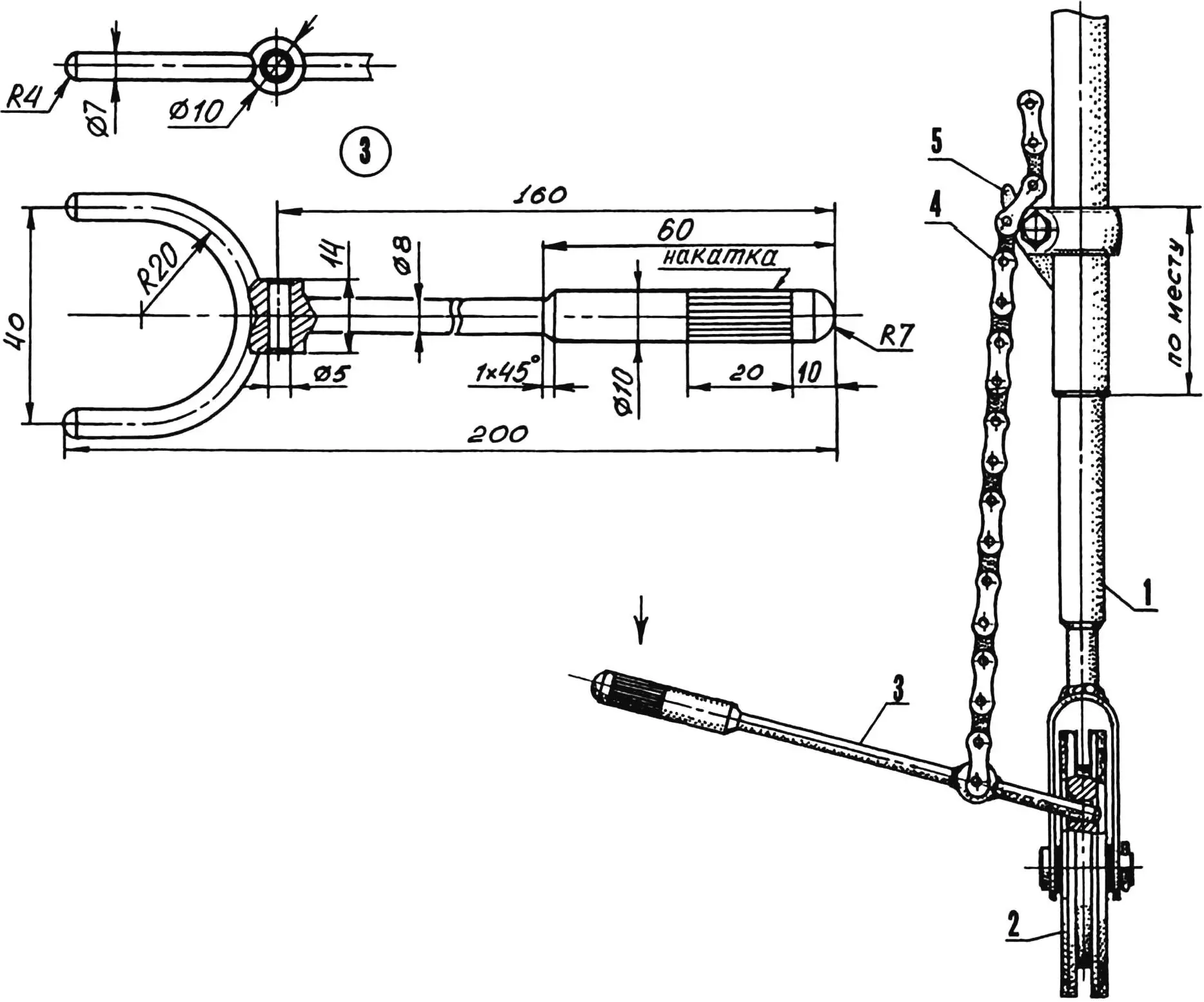
1 —main rod of attachment for sharpening saw chains; 2 — guide pulley; 3 — remover lever; 4 — chain PR-15 or PR-12.7; 5 — hook
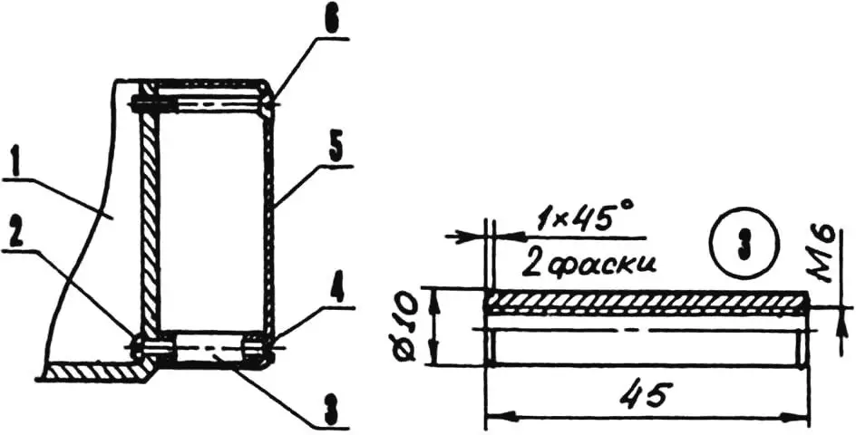
The attachment consists of a swivel console with a simple clamping device, a rod, upper and lower rods, a spring, and a guide pulley. The most complex units here are the rod (fig. 14), riveted from a welded bracket, cylinder, and insert, and the swivel console.
In addition, the attachment is supplemented with a holder (motorcycle handlebar clamp) and a hook, which are necessary for putting on and removing saw chains (the remover design is shown in a separate drawing).
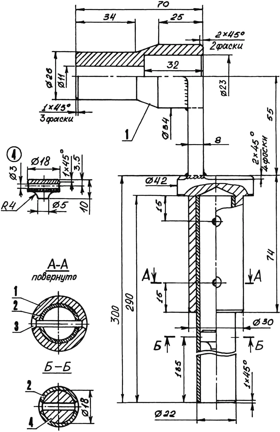
1 — welded bracket (steel); 2 — cylinder (steel, tube 22×2); 3 — rivet (steel, Ø3, 3 pcs.); 4 — insert (steel)
The rod is welded from three parts: a horizontal bushing, a vertical cup, and a connecting wall.
Unusual roller bearings (fig. 15) are located in the horizontal bushing, consisting only of outer races (tube segments) and a set of rollers. The inner diameter of the races and the diameter of the rollers are calculated so that the shaft with the handle mounted on it rotates in the bearings.
1 — handle with shaft; 2 — PTFE washer (s2); 3 — roller bearings; 4 — drive flange; 5 — spacer washer (s1, 3 pcs.); 6 — driven flange; 7, 13 — compression springs; 8 — adjustment bushing-nut M10; 9 — lock nut M10; 10 — pin (Ø3, L19.5); 11 — rod; 12 — wedge-bushing; 14 — hook for saw chain remover (steel, sheet s2); 15 — clamp, hook holder (from motorcycle); 16 — additional rod; 17 — stud M14; 18 — main rod; 19 — spacer washer (s1, 2 pcs.); 20 — pin; 21 — guide pulley; 22 — bolt M12; 23 — wedge-nut M12; 24 — swivel console
The cup (also a machined part) is intended for clamping in the swivel console hole, which is why it has such thick walls. A thin-walled cylinder with a riveted insert is fixed in the cup.
The limb on the cup rim allows setting the rod (and thus the saw chain) at the angle necessary for sharpening.
Two friction flanges and a compressing spring are fitted on the smooth cylindrical section of the shaft with handle, rotating in the roller bearings of the bushing.
One of the flanges is the drive, as it is connected to the shaft by a short pin pressed into the radial hole of the shaft (after inserting the latter into the bearings). The second, driven flange is connected to the drive by three of its lugs. The spring compression force is adjusted by a bushing-nut, fixed with a lock nut.
The flanges are called friction because the ridges of the saw chain put on for sharpening get between them and are held by friction forces caused by spring compression. Therefore, with any turn of the handle, the saw chain rotates, bringing each of its teeth under the abrasive wheel, as required.
This simple solution allows quality sharpening of chains of different pitches and eliminates the need for a whole set of additional removable sprockets.
In addition to pitch, saw chains of different brands also differ in length. But a solution has been found here too: the main rod of the attachment can be extended by 100 mm using an additional rod and a connecting threaded stud (hand-tightened).
The saw chain is put on the attachment and removed from it with the same tool—a special remover (fig. 13). There is no need to describe its device, since everything is clear from the drawing.
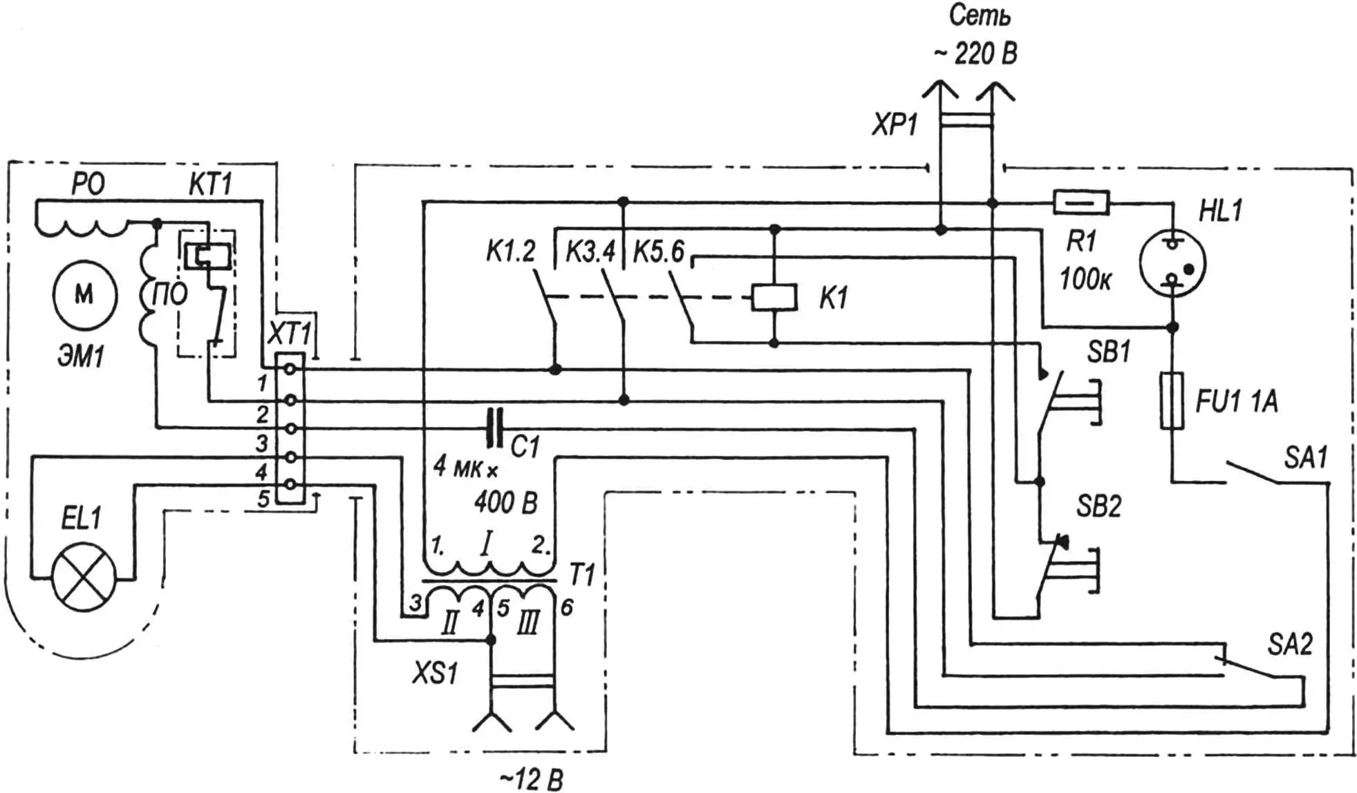
EL1 — electric lamp model A12-21; ЭМ1 — electric motor model ABE-0.71-4С (180 W, 1350 rpm); РО — working winding; ПО — starting winding; КТ1 — thermal relay model PT-10; ХТ1 — connector block; Т1 — transformer model ТВК-110ЛМ; XS1 — outlet (~12 V, 20 W); С1 — capacitor model КБГ; К1 —electromagnetic relay model П36; ХР1 — power cord model ПРС-ВП; HL1 — indicator neon lamp model ТН-0.2; FU1 — fuse; SА1, SA2 — toggle switches model ТП1-2; SB1, SB2 — buttons model КЕ
The machine’s electrical equipment kit (electrical diagram—fig. 16) includes a motor type АВЕ-0.71-4С with a distribution box (fig. 18) and a control panel (fig. 17).
The START and STOP buttons are on the right front panel of the control panel, and on the left is an outlet for additional consumers with a power of no more than 20 W, powered by alternating electrical voltage of 12 V. Since the control panel is attached to the power bracket, it automatically repeats its circular movements. Therefore, access to the control buttons is always convenient.
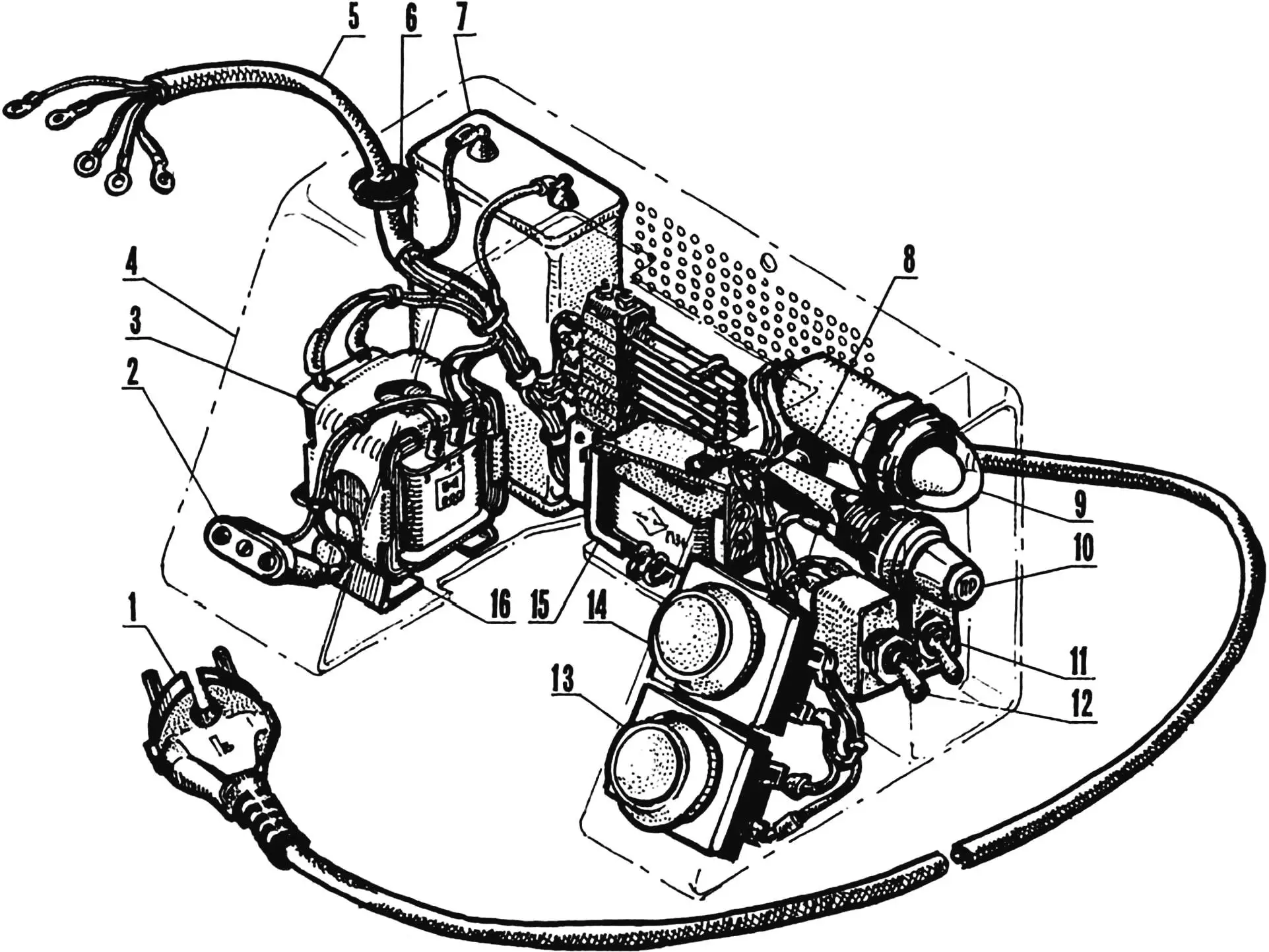
1 — power cord plug ~220 V; 2 — outlet ~12 V; 3 — transformer; 4 — control panel housing contour; 5 — common cable exit; 6, 8 — insulating bushings; 7 — capacitor; 9 — indicator lamp cap; 10 — fuse; 11, 12 — toggle switches; 13, 14 — control buttons; 15 — electromagnetic relay; 16 — transformer mounting bracket
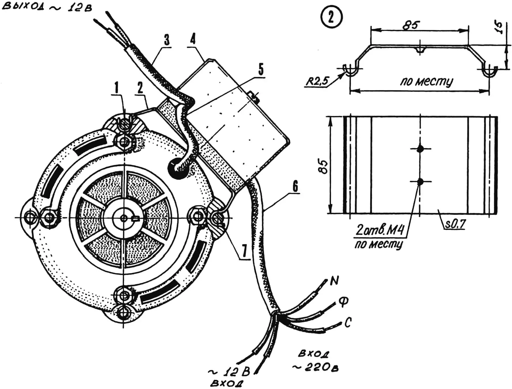
1, 7 — electric motor housing tie bolts; 2 — box mounting bracket; 3 — lamp power cable; 4 — distribution box; 5 — electric motor power cable; 6 — common cable
1 — power bracket; 2, 4 —short screws M6 (4 pcs.); 3 — spacer bushing M6 (2 pcs.); 5 — control panel housing; 6 — long screw M6
Readers who want to reproduce the design of the proposed machine will undoubtedly appreciate its capabilities not only when sharpening saw chains but also in other operations.
For example, another attachment or, rather, a whole set of attachments is designed for sharpening locksmith and carpentry tools, drills, wood and metal cutters, as well as for cutting metals and processing wood (fig. 21).
1 — swivel console; 2 — bolt M8 with shaped head (2 pcs.); 3 — swivel table; 4 — protractor flange; 5 — nut M8 (2 pcs.); 6 — stop screw M5; 7 — tool rest; 8 — angular stop; 9, 22 — tools being sharpened (drill and plane iron); 10 — lumber being resawn; 11 — circular saw; 12 — shield; 13, 20 — thumb screws M8 (3 pcs.); 14 — work table; 15 — movable guide; 16 — work table rotation axis; 17 — work table fixing screw M6; 18 — machine pendulum; 19 — stop screw M8; 21 — holder; 23 — vise
The basis of the set is a swivel table with a vertical axis inserted into the swivel console (with the attachment for sharpening saw chains removed), on which various holders are mounted with two bolts with shaped heads.
For example, vises are installed on the swivel table to fix the metal and wooden parts being processed; and for tool sharpening—a protractor flange with a T-shaped tool rest, which can be turned to the required angle to the vertical. Either the tool being sharpened itself, for example, a plane iron (pressed to the tool rest with a special holder with thumb screws), or an angular stop with a groove in which drills are placed, are positioned on the tool rest.
Unfortunately, the power of the АВЕ-0.71-4С electric motor (180 W) is often insufficient for processing massive wooden parts. However, if an electric motor type АОЛ-21-2 (400 W at 2800 rpm) is used, considering that АВЕ and АОЛ motors have the same shaft diameters, mounting stud sizes, and distances between them, then wood processing on the machine will no longer be problematic.
ATTENTION! For the safety of the operator, the machine’s units and parts have no sharp edges or corners. For the same purpose, it is painted with bright alkyd enamel ПФ-115. Nevertheless, when the machine is on, it is recommended to strictly observe safety regulations and work only with protective goggles!
In conclusion, I will tell you where some units and parts of the machine were borrowed from.
The electric motor, drive and driven pulleys—from the СМР-1.5 “Snezhnka” washing machine.
The cylindrical tension spring used in the pendulum balancing mechanism—from the ЗИЛ-130 car hood hinge.
As for the attachment for sharpening saw chains, its shaft with handle is nothing other than one of the screws for mounting the cylinder head cover of the КДМ diesel. The quick-release clamp on the rod is part of a motorcycle handlebar bracket.
All further listed parts—from a decommissioned marine diesel engine model Д6.
The main and additional rods are modified parts of intake valves; the connecting stud is a section of thread from the valve seats of the same valves; the bearing rollers are elements of a high-pressure fuel pump.
Main technical characteristics of the universal sharpening machine
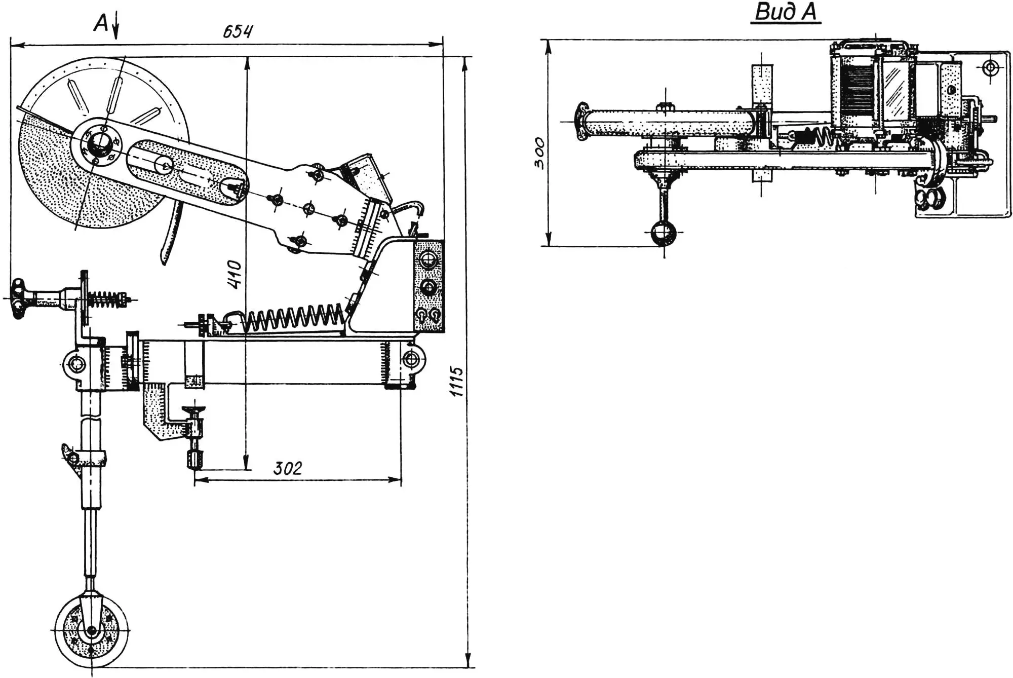
Overall dimensions, mm:
length … 654
width … 300
height … 1115
Mass without attachments, kg … 21
Electric motor type … АВЕ-0.71-4С
Rated motor power, W … 180
Number of revolutions, rpm … 1350
Maximum power consumed by machine, W … 250
Rated voltage, V … 220
Supply network frequency, Hz … 50
Machine operating mode … continuous
Transmission type … belt
Gear ratio … 1
Number of operations (sharpening, cutting, sawing, etc.) performed on machine:
main … 5
total … up to 10
Maximum dimensions of applied abrasive wheel, mm:
diameter … 230
thickness … 25
“Modelist-Konstruktor” No. 1’2004, No. 2’2004, V. PETROV
Recommend to read
 CONTOUR PROMOCODE
Marine modelling — the most exciting activity for children of middle and older age. And in Mature and in old age they enthusiastically engaged people interested in the study of the... Wheels under control
Camber and toe-in of a passenger car’s wheels can be adjusted very accurately without going to a service station. You only need some basic metalworking skills and simple tools to make your...
