
When it comes to building a country house, it almost always implies that all “amenities” will be equipped in the yard. These include a shower (bathroom), toilet, bathhouse, and washbasin… This means that in any, even the most miserable weather, one will have to curse everything and make one’s way to such “amenities.” And only in very rare cases, when building a house, fully “urban” common facilities are included in its design.
The obstacle to civilized arrangement of common facilities is the absence of a centralized sewerage system. However, on almost any plot, it is possible to organize the neutralization of domestic wastewater, including fecal waste, with subsequent full or partial use or removal beyond the plot. Well, a country house with a sewerage system can be equipped with the most modern sanitary and technical equipment.
In a country house, the sanitary and hygienic complex can be significantly more complete than in a standard urban apartment. In addition to a toilet, bathroom with washbasin, and kitchen sink, one can also equip another toilet with washbasin, a bathroom-laundry room, a washroom with bidet, a washroom near the garage or workshop, as well as a bathhouse or sauna.
So, let’s start with the most important thing — removal and neutralization of domestic wastewater. For this, structures of mainly two types are used: cesspools with periodic removal of accumulated waste and local treatment facilities, through which wastewater is neutralized by settling and biological treatment.
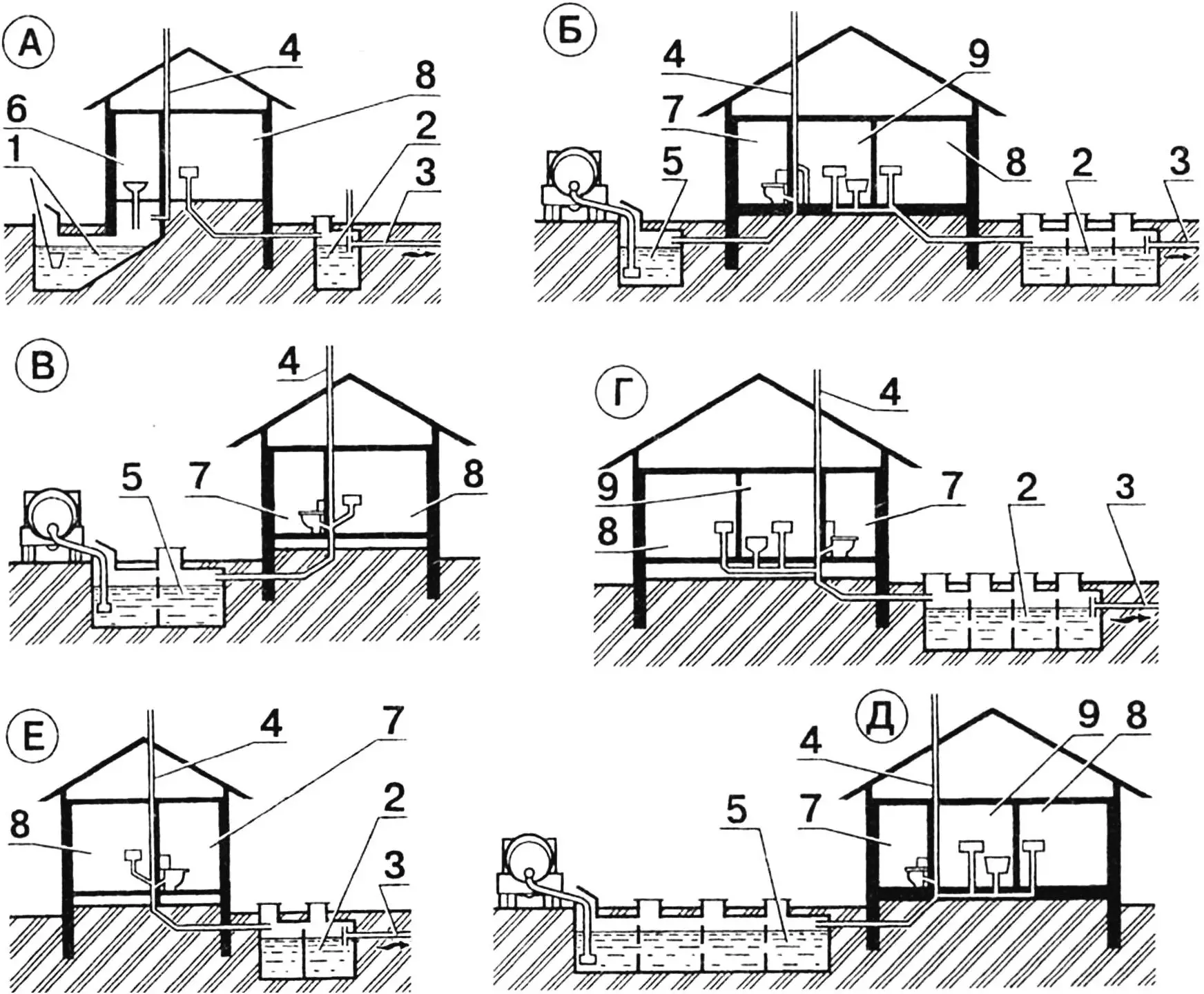
A — simplified improvement with a pit latrine, cesspool, and sink drain to treatment facilities, B — full improvement with toilet drains to cesspool and sink and bathtub drains to treatment facilities, C — incomplete improvement with toilet and sink drain to cesspool, D — full improvement with toilet, sink, and bathtub drain to treatment facilities, E — full improvement with toilet, sink, and bathtub drain to cesspool, F — incomplete improvement with toilet and sink drain to treatment facilities.
Numbers indicate:
1 — pit latrine cesspool, 2 — septic tank, 3 — outlet to treatment facilities, 4 — ventilation riser, 5 — domestic wastewater cesspool, 6 — pit latrine, 7 — flush toilet, 8 — kitchen with sink, 9 — bathroom with bathtub and washbasin.
Depending on specific conditions, various options for local sewerage arrangement are possible using both cesspools and treatment facilities. Cesspools are advisable if there are vacuum trucks or with limited wastewater volume, when their utilization within the plot is possible.
A cesspool is an underground container (usually reinforced concrete) with sealed walls and bottom. In frost-susceptible soils, cesspools are designed taking into account frost heave forces: their depth is not above the ground freezing level, external walls are built with an inward slope, and the reinforcement of walls and bottom must have a rigid connection. If the groundwater level is located above the bottom of the container, it is necessary to isolate the latter using roofing felt, pasting it on the structure walls. To prevent the cesspool contents from freezing, it is advisable to lay insulation over the cover: slag, expanded clay, or foam plastic with protection from moisture by clay and roll waterproofing.
The most convenient form of a cesspool is cylindrical. Such a container resists lateral soil pressure well, and its construction is relatively inexpensive — less concrete is required than for a cesspool of another shape. With a tank diameter of 2…2.5 m, the wall thickness is 80…120 mm, with a larger diameter — up to 150 mm. The volume of the underground tank should be at least 10 m3, and this is not that much. If only a kitchen sink and flush toilet are installed in your house, such a volume will be filled in just a month.
The simplest way, of course, is to construct a container from ready-made or self-cast reinforced concrete rings. If there is a need for a large-capacity cesspool, it is not worth building a concrete tank of large diameter; it is simpler to make several ordinary containers connected to each other by water-air transfer pipes. Each compartment should be equipped with an inspection hatch. Cesspool ventilation is preferably provided through an in-house smoke-ventilation block.
Of course, by constructing a cesspool, you make the reliability of sanitary and technical equipment dependent on cleaning services. Sewerage with local treatment facilities has significantly greater autonomy.
The contamination of domestic wastewater is determined mainly by the presence of organic substances in them, which must be mineralized during treatment. This is usually done in two stages: first, wastewater enters special settling tanks (septic tanks), where they stratify and clarify, and then undergo further treatment at biological treatment facilities.
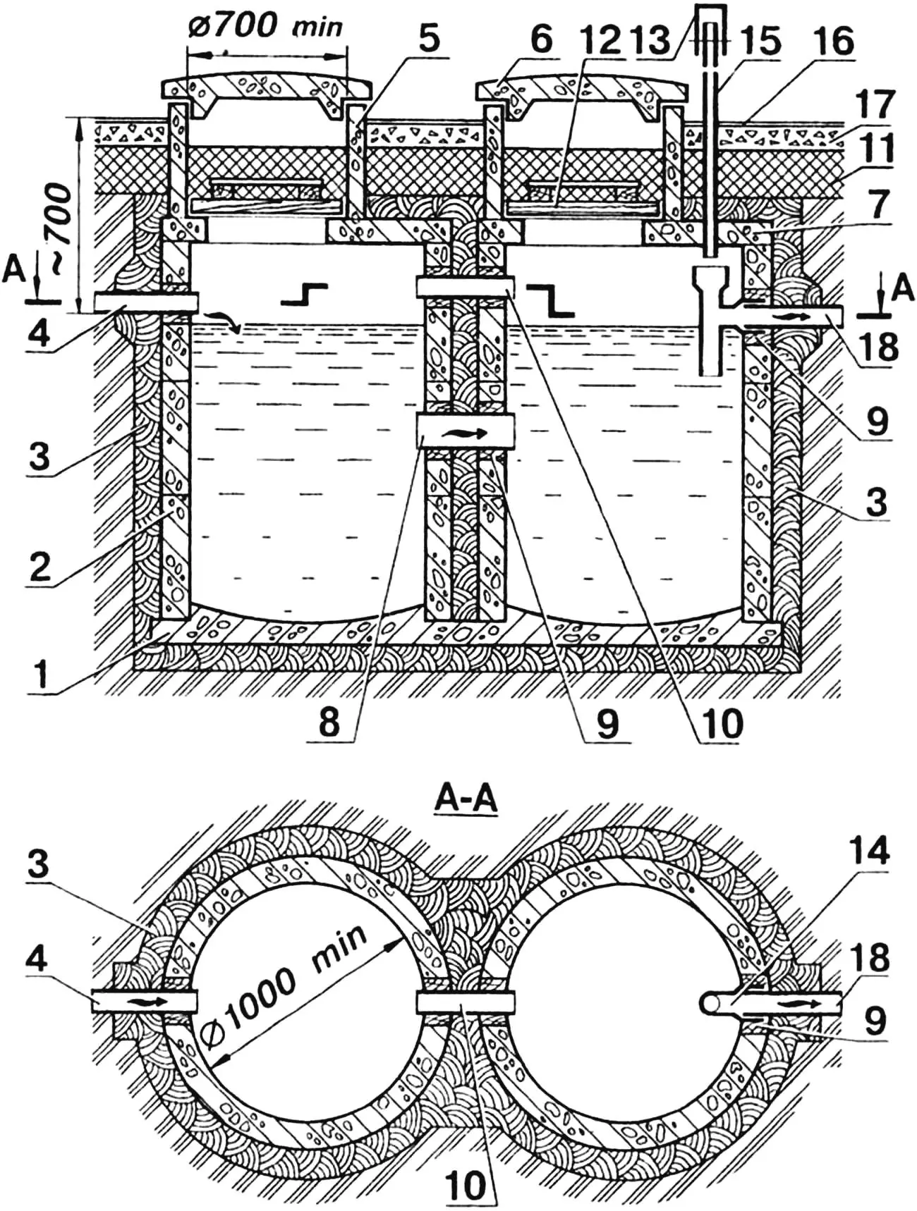
1 — bottom (monolithic reinforced concrete), 2 — wall (reinforced concrete ring), 3 — waterproofing (compacted clay), 4 — inlet channel (pipe Ø 100), 5 — ring (reinforced concrete), 6 — hatch cover (reinforced concrete), 7 — cover slab with hatch opening (reinforced concrete), 8 — water transfer (pipe Ø 150), 9 — sealing of through openings with tarred oakum followed by two-sided caulking of joints with cement-sand mortar, 10 — air transfer (pipe Ø 100), 11 — insulation, 12 — wooden hatch cover, 13 — deflector-weather vane, I4 — tee, 15 — ventilation riser (pipe Ø 50…80), 16 — blind area (concrete or asphalt), 17 — backfill (crushed stone), 18 — outlet channel (pipe Ø 100).
A septic tank is a sealed container through which domestic wastewater passes at low speed (over four or more days). Suspended matter settles, and clarified water is directed for subsequent biological treatment. The organic part of the sludge over six to twelve months, under the influence of anaerobic microorganisms, decomposes and turns into gaseous and soluble mineral substances. To improve the treatment process, the septic tank is divided into several separate chambers connected by pipes. The septic tank size is chosen so that its internal volume exceeds the average daily wastewater volume by 3…5 times. For example, with a flow of 200 l/day, the septic tank volume should be at least 0.6 m3.
A septic tank is arranged approximately the same as a cesspool: it is a sealed container with an inspection hatch, protected from freezing, as well as from rainwater and floodwater. Through the hatch, the wastewater surface is periodically cleaned of a crust of floating sludge particles, and the bottom is cleaned of sludge deposits once or twice a year. By the way, it is not recommended to remove all the sludge; about 20% of this mass should be left at the bottom for the reproduction of bacteria that promote the decomposition of organic substances.
After passing through the septic tank, clarified wastewater enters biological treatment filtering facilities. This method is based on the use of the vital activity of microorganisms found in the filtering material. They quickly oxidize organic substances and convert them into harmless decomposition products. Since the vital activity of aerobic bacteria is associated with oxygen consumption, biological treatment facilities must provide the greatest area of contact between wastewater and air. To remove decomposition products harmful to bacterial life (for example, carbon dioxide), effective ventilation is provided.
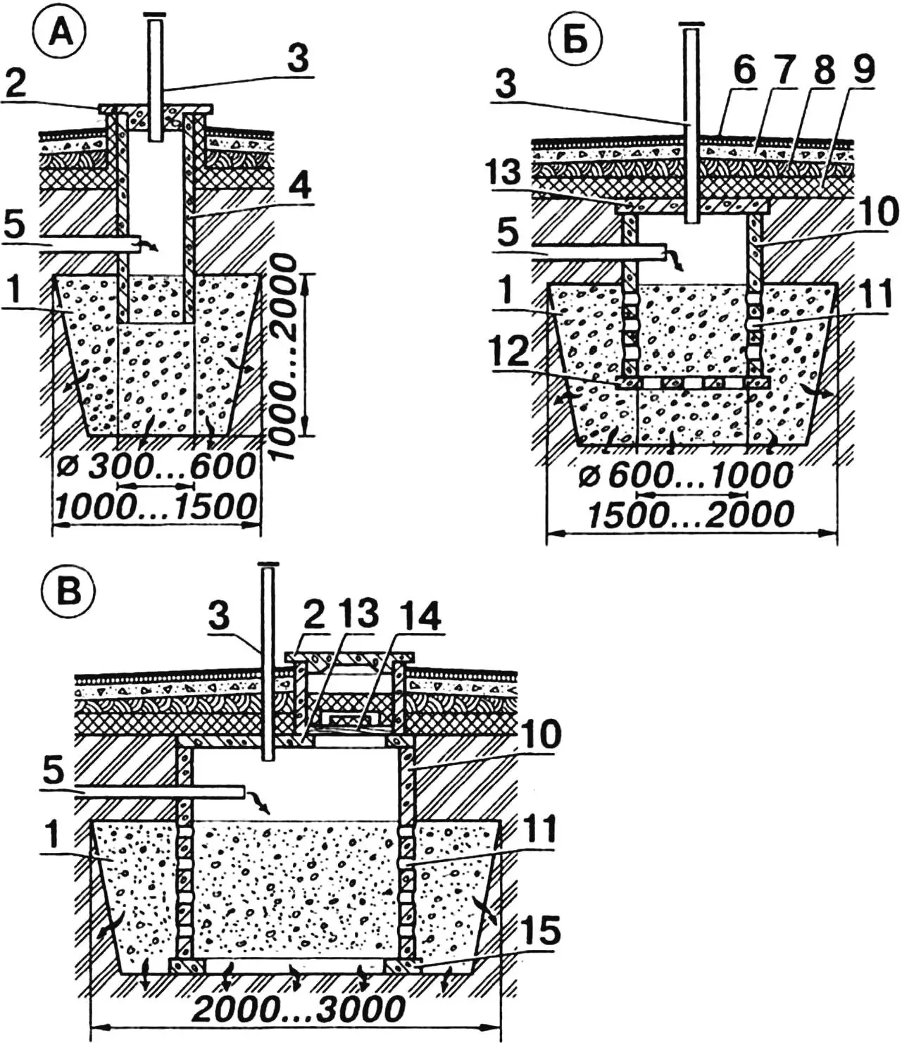
A — from asbestos-cement or concrete pipes Ø 300…600, B — from precast or monolithic reinforced concrete rings Ø 600…1000, C — with inspection hatch.
Numbers indicate:
1 — filtering material (broken brick, crushed stone, slag, or coarse sand), 2 — hatch cover (reinforced concrete), 3 — ventilation riser, 4 — well wall (asbestos-cement or reinforced concrete pipe), 5 — inlet channel, 6 — blind area, 7 — crushed stone backfill, 8 — insulation (clay), 9 — insulation, 10 — ring (reinforced concrete), 11 — opening for filtrate passage, 12 — bottom (reinforced concrete), 13 — cover (reinforced concrete), 14 — hatch cover (wood), 15 — support ring (monolithic concrete).
The type of filtering device is chosen depending on soil characteristics affecting wastewater treatment efficiency, flow volume, and plot size. The simplest and cheapest treatment facility is a filtering well. It functions due to the natural ability of porous soils to pass water through themselves and divert it beyond the saturated area. The throughput capacity of such a device depends on the absorption properties of the soil located at a depth of 1…3 m and the area of contact with it of wastewater. Well, the degree of biological treatment depends on the quantity and quality of filtering material laid in the well instead of extracted soil, on the surface of which sludge populated with microorganisms forms. Using organic residues as nutrients, microorganisms mineralize and purify wastewater entering the well.
The required filtering surface area is not difficult to calculate if one knows that water absorption of 1 m2 of sandy soils is 60…100 l/day (sandy loam — 30…50 l). For example, with a wastewater volume of 600 l/day, the working surface of sandy soils located along the perimeter of the filtering material should be 6…10 m2. For sandy loam soils, this value increases to 12…20 m2. Filtering material can be granite or brick crushed stone, pebbles, slag, coke, peat, or even sand. In the well, these materials are arranged so that larger components are in the center, and smaller ones are on the periphery.
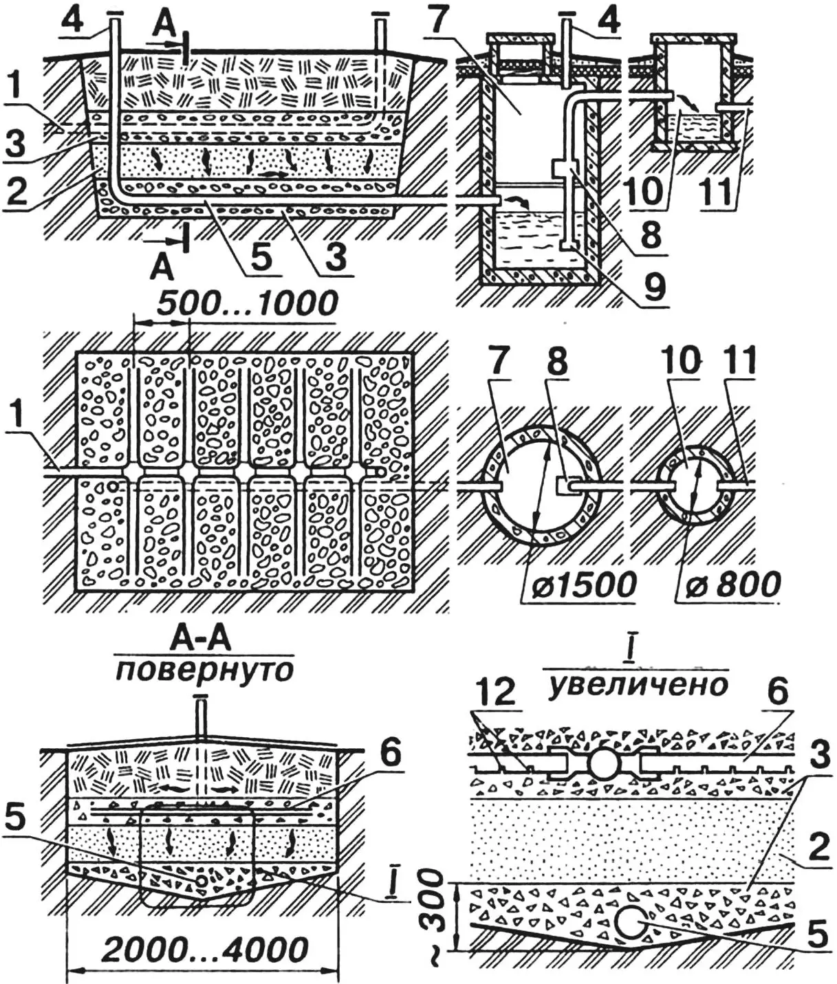
1 — inlet channel (from septic tank), 2 — coarse and medium sand, 3 — large-pore filtering material (crushed stone, gravel, slag, or expanded clay), 4 — ventilation riser, 5 — drainage pipe, 6 — irrigation pipe, 7 — wastewater transfer receiving well, 8 — electric pump, 9 — water intake filter, 10 — distribution well, 11 — drain pipe, 12 — openings for filtrate discharge.
The structural scheme of a filtering well is chosen depending on its throughput capacity and materials used. In any case, an air cavity equipped with a cover is left above the central part of the filtering material. Air exchange in the cavity is carried out through a ventilation riser. Openings for filtrate passage from the central part to the periphery are provided in the well walls. The height of the filtering material is 1…2 m, while the distance from the well bottom to the groundwater level should be at least 1 m.
If for some reason it is not possible to construct filtering wells, underground filtration fields are equipped on the plot. Their basis is an irrigation system of perforated pipes laid in earthen trenches, through which wastewater pre-treated in a septic tank passes. Wastewater absorption occurs in the surface soil layer to a depth of 1 m. The calculated soil area through which filtration is carried out should be 2 times larger than for filtering wells. So, with a flow of 600 l/day, the total working area of trenches in sandy soils is 12…20 m2, and in sandy loam — 25…40 m2. With a filtering layer thickness of 250 mm and bottom width of 500 mm, the working surface of 1 linear meter of trench is 1 m2, respectively, the total length of trenches will be: for sandy soil — 12…20 m, for sandy loam — 25…40 m.
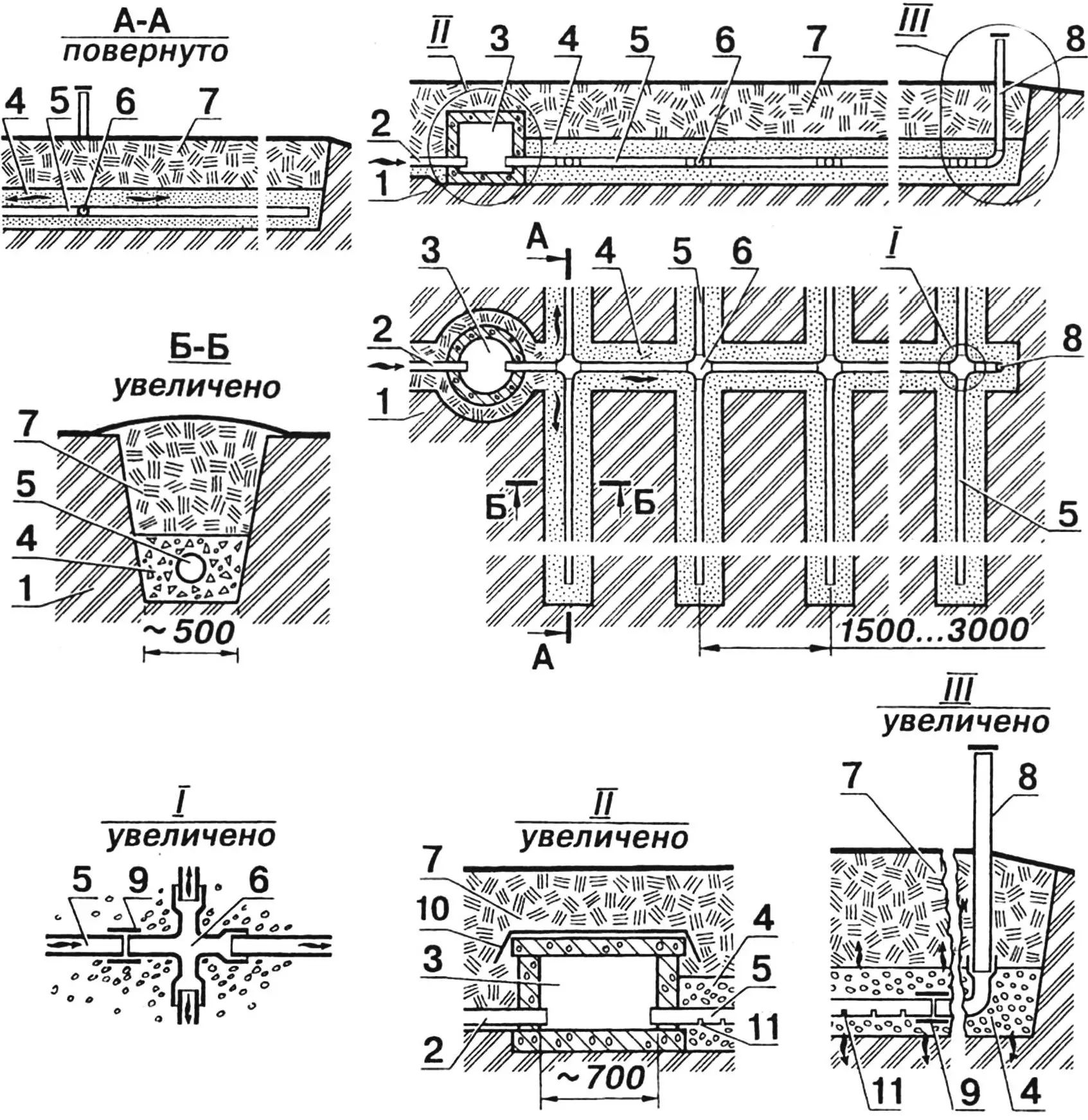
1 — native (undisturbed) soil, 2 — inlet channel (from septic tank), 3 — distribution well, 4 — filtering material, 5 — irrigation pipes, 6 — connection joint (fittings), 7 — fill soil, 8 — ventilation riser, 9 — connecting overlay ring, 10 — roll waterproofing, 11 — opening for filtrate discharge.
Underground filtration fields are usually located no closer than 15 m from the residential house. Wastewater that has passed through the septic tank is directed to a distribution well, and from it through irrigation pipes — directly to the filtration fields. For the irrigation system, asbestos-cement or ceramic pipes with a diameter of about 100 mm are used, which are laid in trenches in a layer of filtering material 200…300 mm thick with a slope of 0.003…0.005 toward the drain. To pass wastewater, cuts are made in the lower part of asbestos-cement pipes to half their diameter, 15…20 mm wide, with a pitch of 150…200 mm, and holes are drilled in ceramic ones. For the same purpose, pipes are laid with gaps 20…30 mm wide, which are covered from above with a roofing felt strip. To prevent rainwater and floodwater from entering the trench, after backfilling it is covered with roofing felt, and a layer of soil is placed on top of it. To supply air to the filtering layer, ventilation risers with a diameter of about 100 mm and a height above ground level of 0.5…1 m are installed at the ends of distribution pipes.
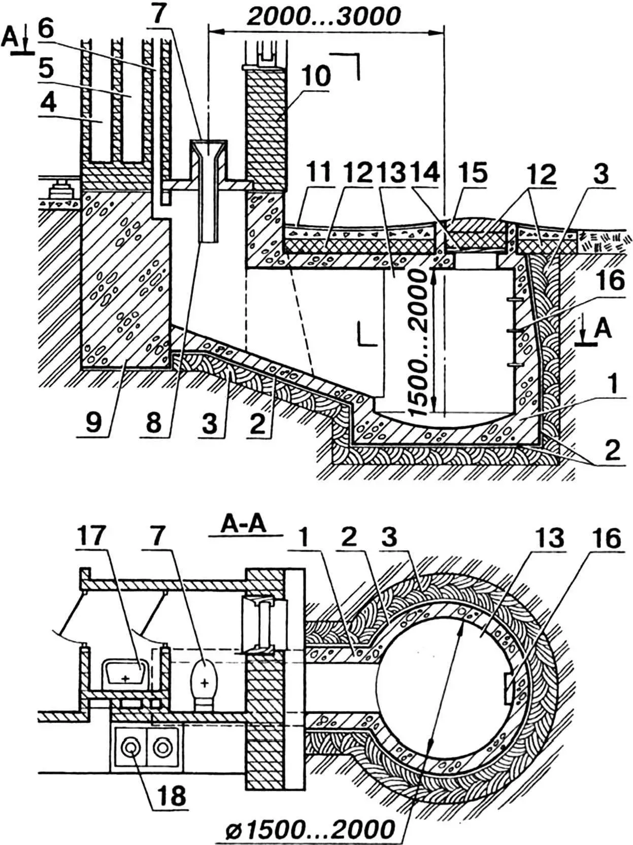
1 — tank (reinforced concrete), 2 — roll waterproofing (with high groundwater level), 3 — waterproofing from compacted fat clay, 4 — ventilation channel for kitchen, 5 — smoke channel, 6 — pit latrine channel, 7 — toilet lid, 8 — vent pipe, 9 — smoke-ventilation block foundation, 10 — external wall, 11 — blind area, 12 — insulation (slag, expanded clay, foam plastic), 13 — pit latrine cesspool, 14 — wooden hatch cover, 15 — cast iron or reinforced concrete hatch cover, 16 — metal brackets, 17 — washbasin in airlock, 18 — solid fuel stove.
On loamy and clayey soils with low (practically zero) water absorption, sand-gravel filters are used. Wastewater that has passed through such treatment facilities is diverted beyond the plot — to a drainage ditch, trench, or ravine. A sand-gravel filter is a trench or pit filled with filtering material, in the thickness of which, at levels spaced 1…1.5 m apart in height, irrigation and drainage networks of asbestos-cement or ceramic pipes with a diameter of about 100 mm are placed. At the pipe level, two layers of large-pore filtering material are laid — for example, gravel, crushed stone, or slag, and the space between them is filled with coarse sand. The distance between parallel rows of irrigation pipes should be 0.5…1 m, the height of the sand filter — at least 0.5 m, and the pit area — in direct proportion to the wastewater volume. In calculations, it should be borne in mind that through 1 m2 of the horizontal surface of a sand-gravel filter, 60…100 l of wastewater passes per day. If the daily wastewater volume is 600 l, then a pit with an area of 6…10 m2 will be required.
Due to the fact that the outlet pipe in a sand-gravel filter is located at a depth of 1.5…2 m, gravity discharge of treated wastewater beyond the plot turns out to be impossible. In this case, water that has passed through the sand-gravel filter has to be directed to a surface drain using a transfer station with an electric pump, usually equipped with a small intermediate tank with a float level sensor, which allows the pump to operate in automatic mode. Interestingly, in summer, treated wastewater can quite be used for watering the garden and vegetable garden.
I. KHOROSHEVSKY
Recommend to read
 THE BEARING IN ONE PLACE
To install the ball bearing in the workplace, it is necessary to produce it under the special case that is often associated with certain difficulties. Here is one simplified but reliable... INSTEAD OF ROULETTE
Fishing pochuchut on himself, saying boastfully among them is easy to determine the bruising above the elbow so he shows off the size fishing line fish. Hand will be more whole, if on...
