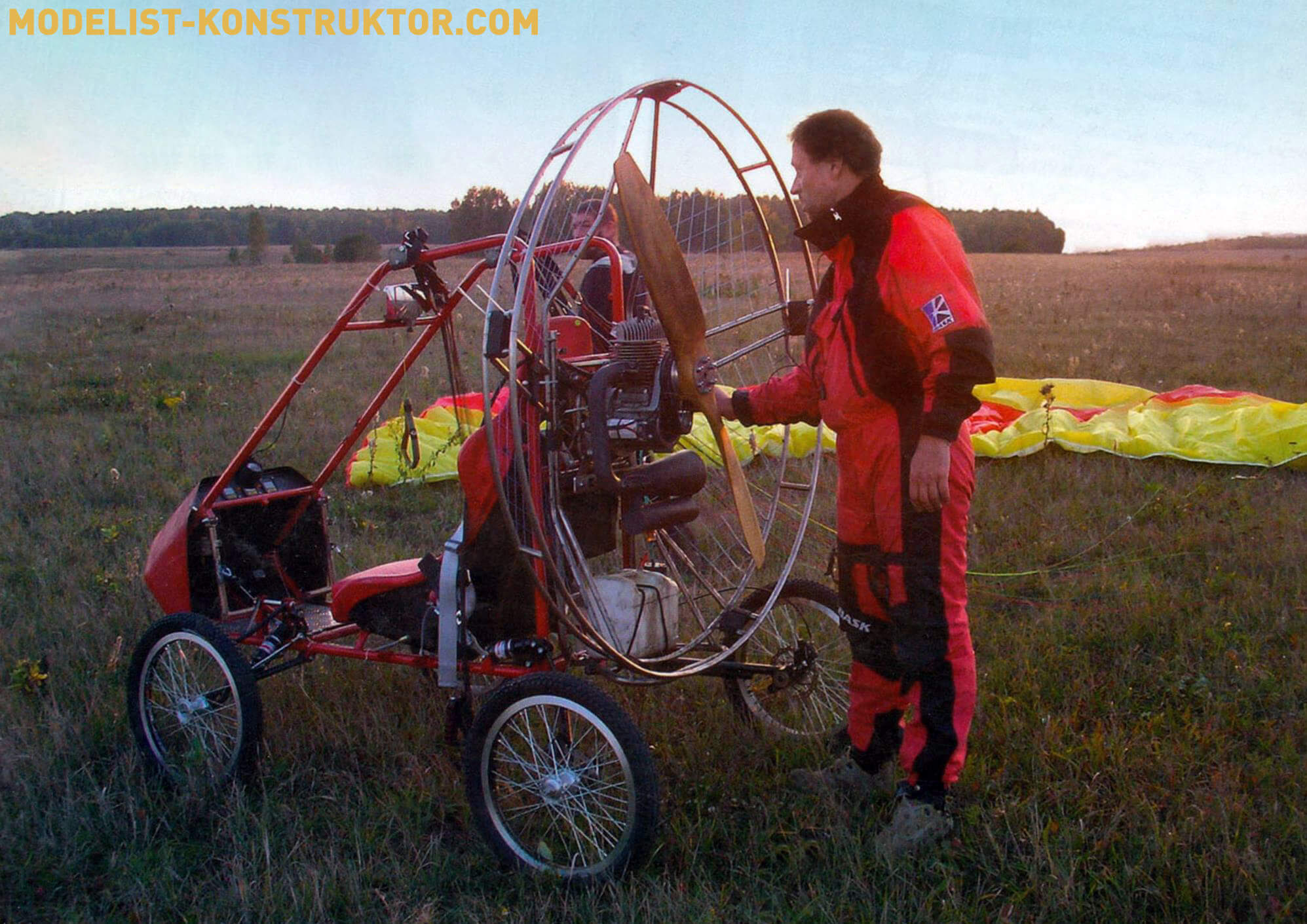
Construction of a cart for a paraglider was preceded by a simple passion for paragliding, which did not come immediately. Initially, I flew on airplanes (I have a pilot’s license) and hang gliders. But once I flew on a paraglider, I became seriously interested in it. I think it’s comparable to sailing a yacht with a sail. Only better.
Initially, like most paragliders, I used a regular three-wheeled cart for takeoff and landing. I won’t talk much about all its shortcomings (they are known to paraglider pilots). But the most unpleasant of them is tipping forward to the side when the wing control skills are insufficient during takeoff and landing. However, even an experienced paraglider on such a cart is not immune from tipping over, for example, in a crosswind. And this is quite dangerous because tipping is more likely the higher the speed, i.e., during takeoff, and especially during landing.
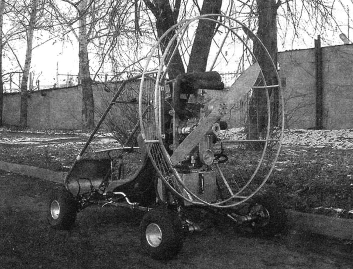
In the end, I decided to make a four-wheeled cart for myself. And when I thought about it, other ideas came to mind—for example: why not use the same cart for moving to the takeoff field and back, especially since the landing can happen quite far from the takeoff place.
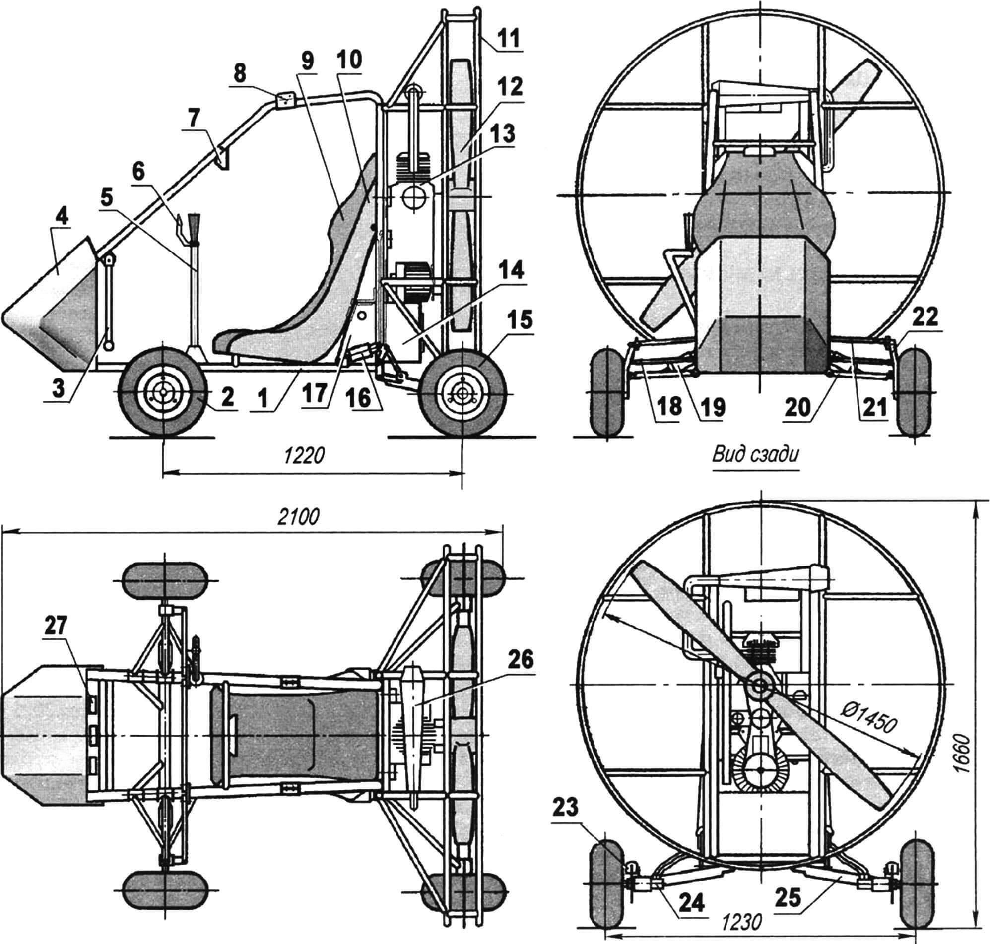
1 — power frame; 2 — front steerable wheel (from a kart, 2 pcs.); 3 — control pedal for front wheels (2 pcs.); 4 — fairing (fiberglass on epoxy binder, s3); 5 — lever-handle; 6 — “gas” control handle; 7 — rearview mirror; 8 — parachute strap attachment bracket (2 pcs.); 9 — seat; 10 — bulkhead; 11 — propeller guard; 12 — propeller; 13 — power unit (N = 27 hp); 14 — fuel tank (V = 15 liters); 15 — rear wheel (from a kart, 2 pcs.); 16 — rear shock absorber (bicycle gas, 2 pcs.); 17 — oil tank (V = 8 liters); 18 — cross-steering tie rod (2 pcs.); 19 — front shock absorber (2 pcs.); 20 — lower front suspension arm (2 pcs.); 21 — upper front suspension arm (2 pcs.); 22 — swivel knuckle (2 pcs.); 23 — brake mechanism (2 pcs.); 24 — hydraulic motor (V = 20 cm3, 2 pcs.); 25 — rear suspension arm (2 pcs.); 26 — muffler; 27 — dashboard
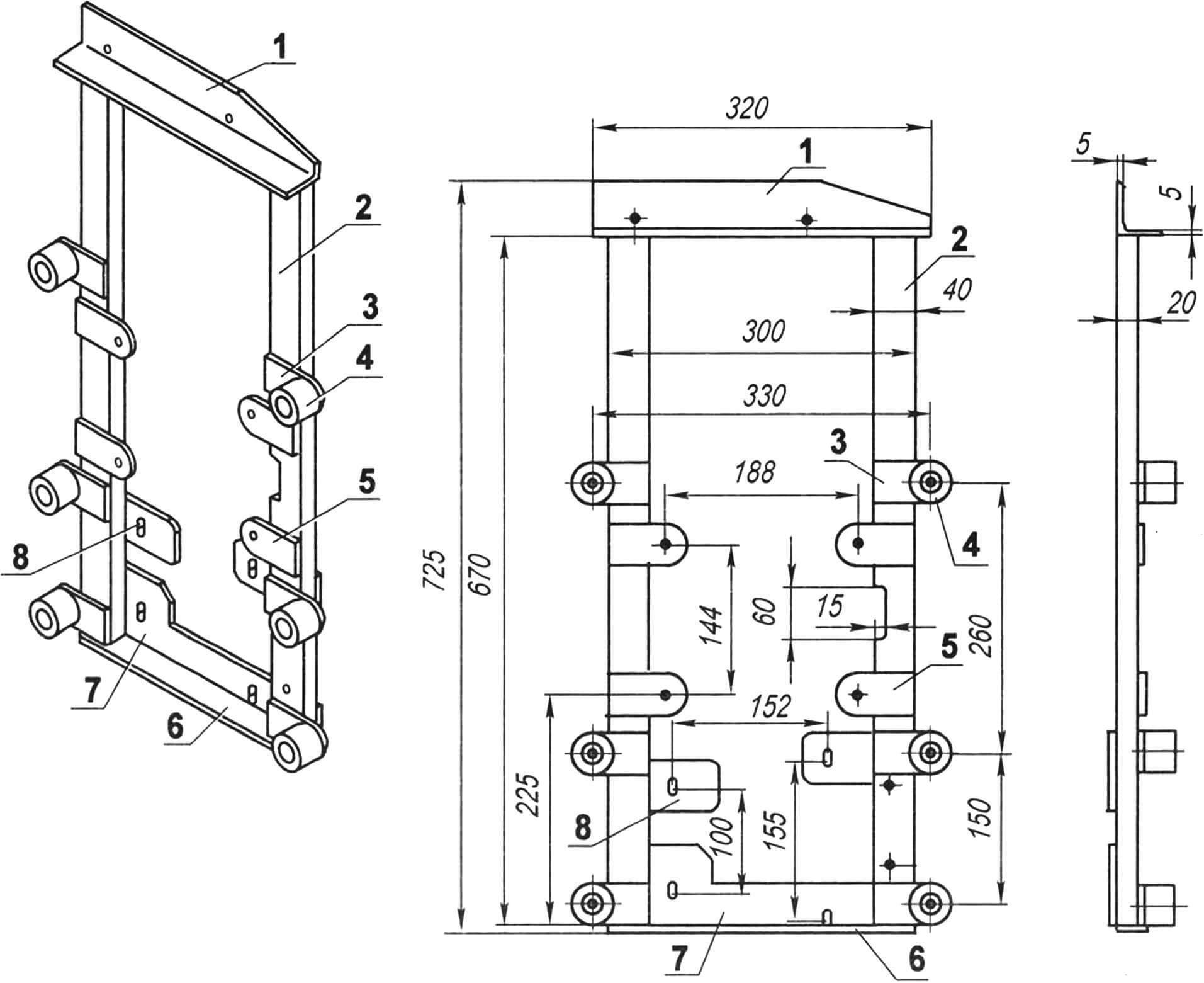
All units and mechanisms—the paramotor, controls, and cart—are based on a spatial frame. The basis of the frame is two identical closed contour elements, resembling a rectangular trapezoid in shape. Although the parts of the contour elements in terms of location and functional purpose can be conditionally divided into a spar (lower horizontal part), pillars (vertical rear and inclined front), and crossbar (upper part), all of them are made as one detail from thin-walled steel tubing (s = 2 mm) with an outer diameter of 28 mm.
I would like to note here that the decision to make the frame from thin-walled steel tubes rather than aluminum ones was made because welding them is much simpler, and the weight loss is insignificant. Moreover, in case of a break, a steel frame can be welded in any nearby workshop, while finding argon welding for aluminum parts can be a challenge.
The elements are connected to each other in several places by crossbars, also made of steel tubes with a diameter of 20 mm (wall thickness — 2 mm). The closed elements also serve as safety arcs.
Various brackets, ears, and lugs for attaching front and rear wheel suspensions, control lever-handle, and seat are welded to the spars.
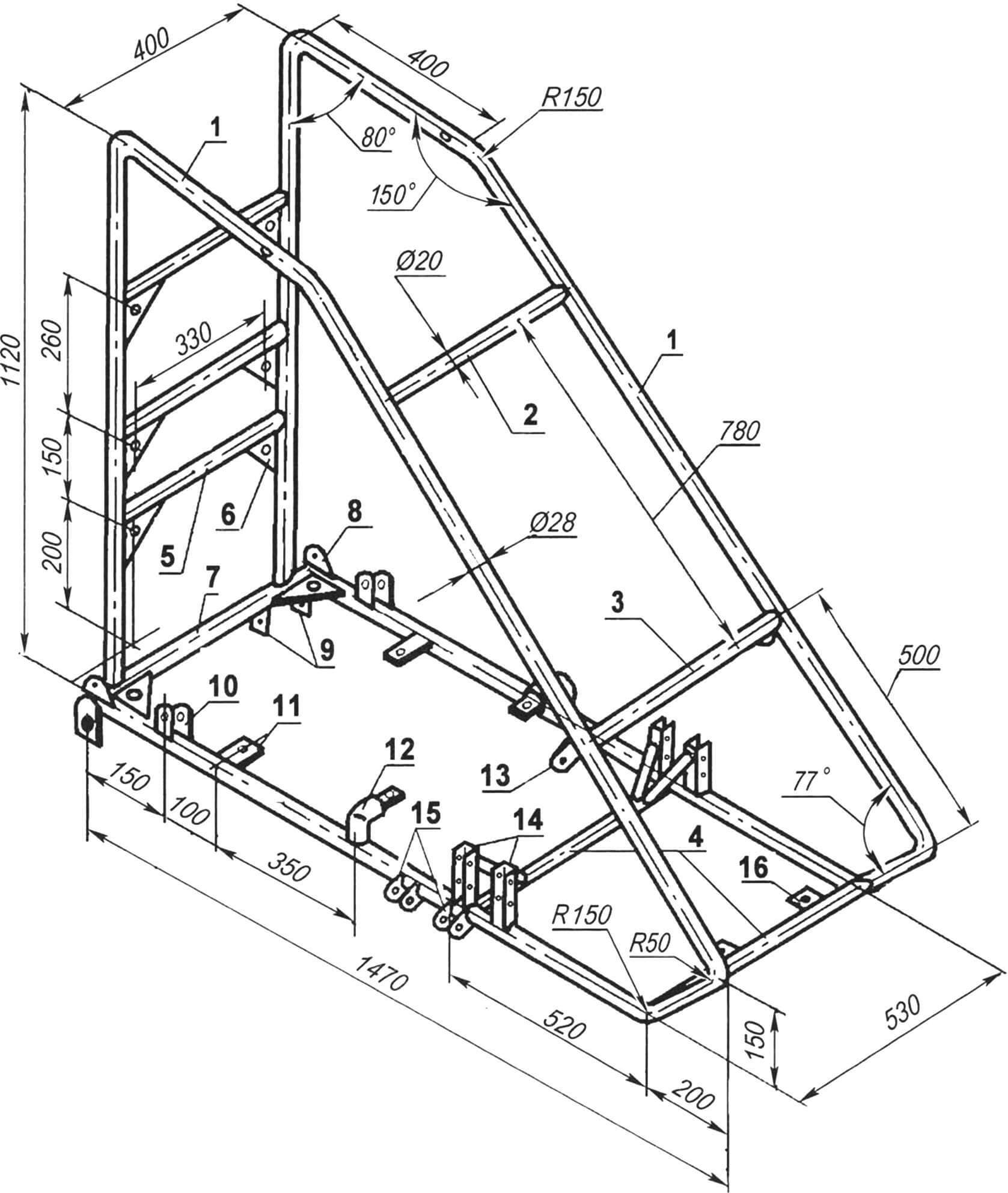
1 — left frame, right — mirror-reflected; 2 — rearview mirror crossbar; 3 — instrument panel crossbar; 4 — floor attachment crossbar; 5 — motor frame attachment crossbar (3 pcs.); 6 — bracket-bracket for attaching the motor frame and fuel tanks (8 pcs.); 7 — traverse; 8 — rocker attachment ear (2 pcs.); 9 — ears for attaching the rear suspension arm lever (2 pairs); 10 — ears for attaching the rear shock absorber (2 pairs); 11 — ears for attaching the rear part of the seat and floor; 12 — brackets for attaching the front part of the seat; 13 — ear for hanging the pedal lever (2 pcs.); 14 — brackets-pillars for attaching the upper arm of the front suspension with struts (2 pairs); 15 — ears for attaching the lower arm of the front suspension (4 pairs); 16 — ear for attaching the floor (2 pcs.)
Attachment nodes for the power unit motor frame and its guard are welded to the vertical posts of the frame elements, as well as in the form of brackets between the posts and the connecting crossbars.
Several lugs are welded to the lower part of the front inclined posts for attaching a shield made of 1-mm aluminum sheet (later replaced the shield with a streamlined one made of fiberglass). The floor is made of 3-mm corrugated aluminum sheet.
1 — upper crossbar (stamped angle 50x50x5); 2 — strut (strip 40×20, 2 pcs.); 3 — bracket-ear for mounting the silent block (sheet s5, 6 pcs.); 4 — silent block (6 pcs.); 5 — bracket-ear for engine mounting (sheet s5, 4 pcs.); 6 — lower crossbar (sheet s5); 7 — vertical shelf-bracket (sheet s5); 8 — bracket-ear for hydraulic pump mounting (steel, sheet s5, 2 pcs.)
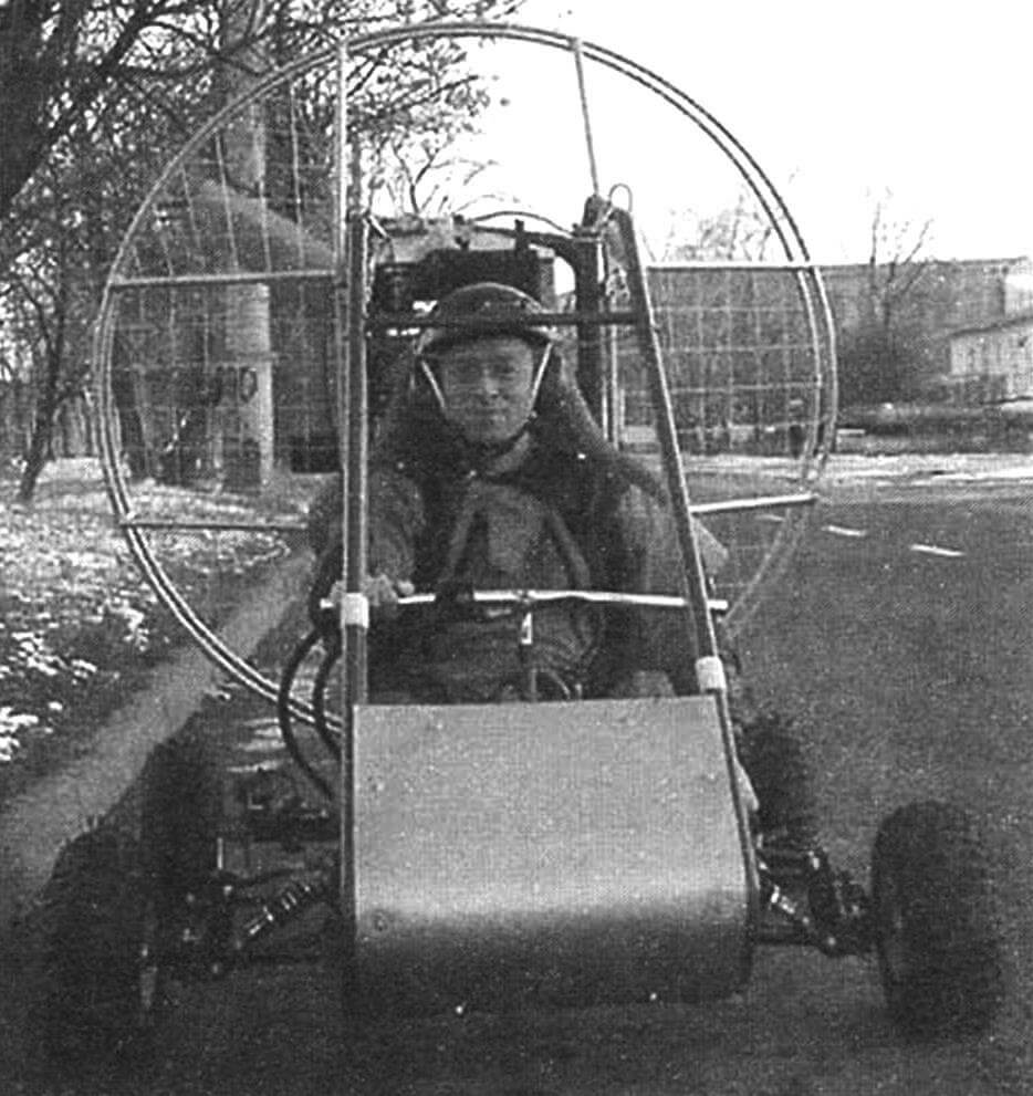
Anticipating, I will say that during the operation, the cart was modified. For example, besides the fairing, the motorcycle-type handlebar was replaced with an aircraft-style lever. The front suspension was strengthened, and other changes were made. But more on that later, as we go through the construction description.
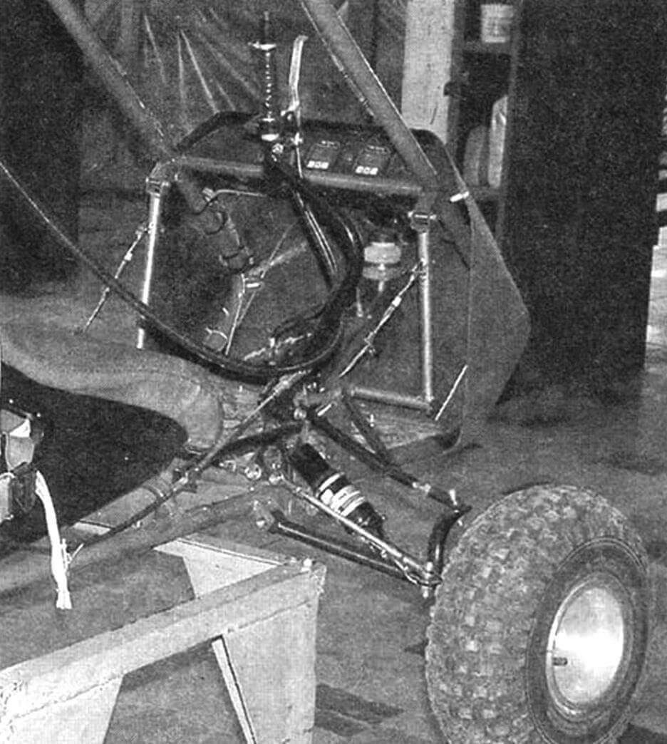
The front wheels are steerable, and the rear wheels are driven by hydraulic motors. All wheels have independent suspension. The rear suspension is single-arm on oblique (longitudinal-transverse) levers, similar to those on “Zaporozhets” cars or, if you will, on “BMW” cars. The front suspension was initially also single-arm (with transverse levers), but later it had to be reinforced with an additional upper lever, making it a parallelogram type. The rear and lower front levers are made of the same steel tube as the crossbars, and the upper front lever is made of a 16mm diameter tube, with the same configuration as the lower one—just mirror-reflected. Bicycle gas shock absorbers are installed on all suspensions (initially, there were spring-hydraulic ones from a moped). The travel of the levers and both suspensions is approximately the same—about 150mm. At the rear, the shock absorber is extended beyond the suspension (to the spar) and is connected to it through a tie rod and rocker.
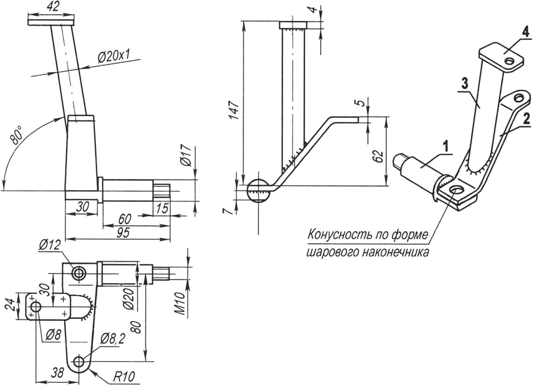
1 — axis (steel, circle 20); 2 — lever (steel, sheet s5); 3 — strut (steel 30KhGSA, pipe 20×1); 4 — bracket for upper front suspension arm attachment (steel, sheet s4)
Constructively, the front suspension is shifted backward from the nose of the vehicle, as if reducing the wheelbase, which is not entirely rational when driving on the ground. However, in the air, due to the displacement of the center of aerodynamic resistance, a reduction in yawing during flight is expected.
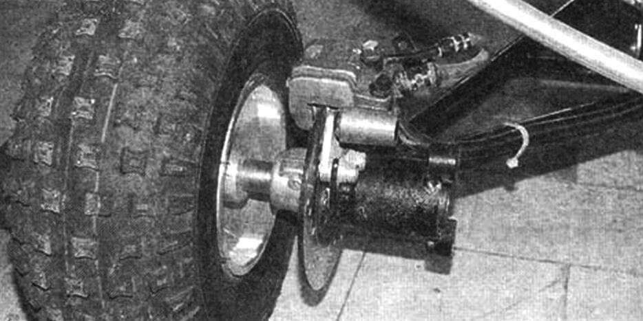
The rear wheels are also, as far as possible, moved backward: their axles are almost in the plane of the propeller. Firstly, this was done for the convenience of layout—there was an improvement in weight distribution along the axes (almost 50×50%); secondly, stability in flight increased due to the backward shift of the center of aerodynamic resistance; thirdly—less chance for a “turtle” (tipping backward) during takeoff.
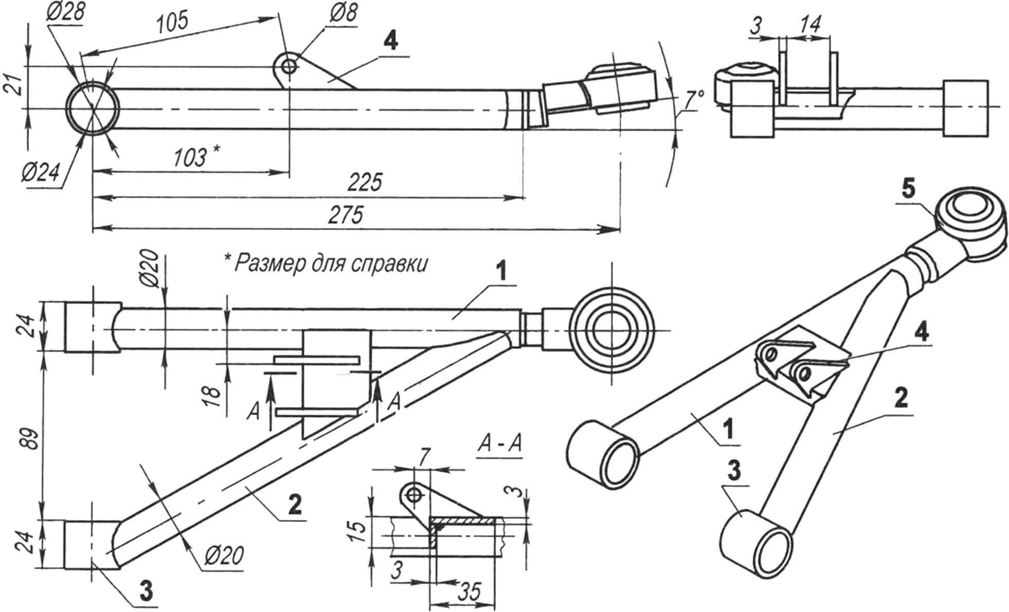
1 — main rod (steel 30KhGSA, tube 20×1); 2 — brace (tube 20×1); 3 — bushing; 4 — bracket (steel, sheet s4); 5 — tip (from VAZ-2108)
The control of the front wheels is of a mixed type, more precisely duplicated—manual and foot. The need to turn them with the feet became apparent during the first takeoffs and landings when hands turned out to be more needed for parachute control.
The foot drive of the front wheels is carried out by pedals through flexible steel cables located under the fairing. The brake pedal is also located here.
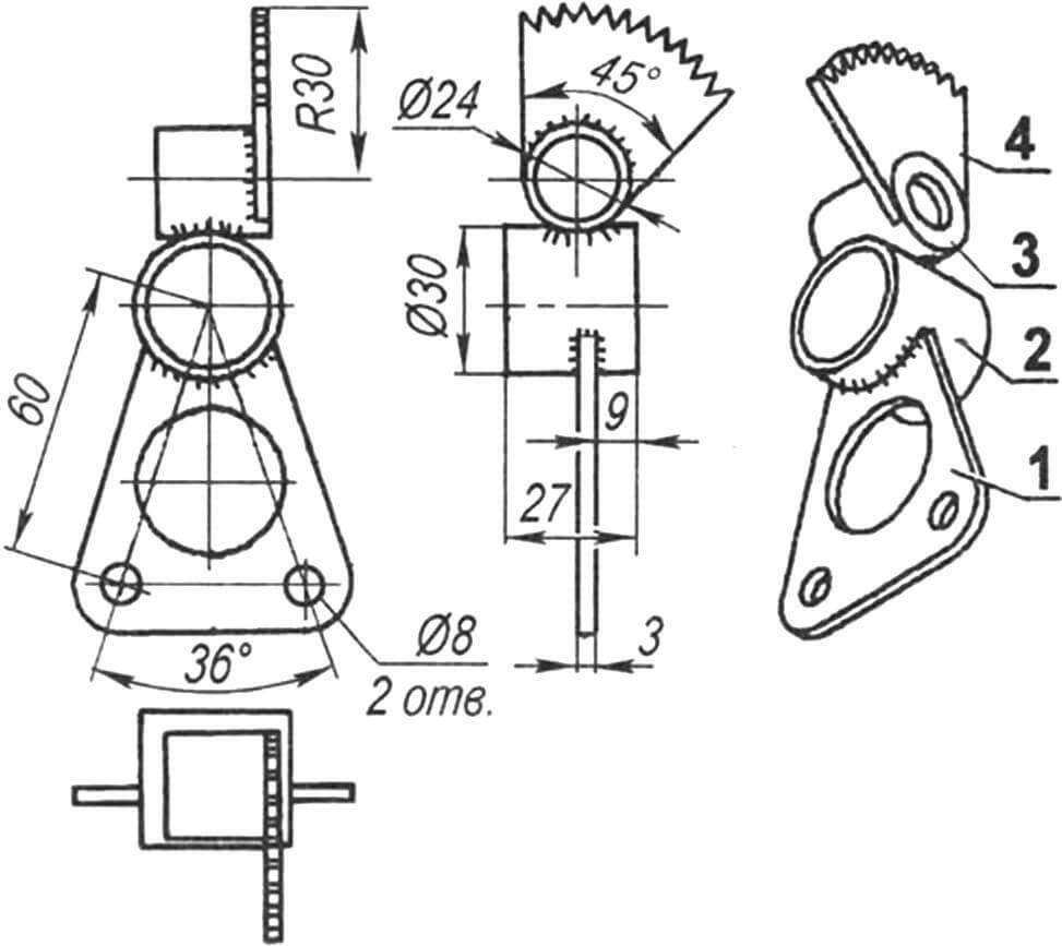
1 — bracket (steel, sheet s3); 2 — bracket bushing (pipe Ø30×2); 3 — ratchet bushing (pipe Ø24×2); 4 — ratchet (from the kickstarter flywheel of a scooter)
Initially, manual control was carried out from a motorcycle-type handlebar through rigid rods. Later, the handlebar was replaced with a lever-handle—similar to those used on airplanes but mounted on the right side of the cart. At the same time, the upper levers and swivel knuckles on the front wheels were replaced.
All control elements of the paramotorized quad bike are concentrated on the handlebar (later on the lever-handle).
Now, onto the main part—the power plant, or more precisely, the power unit, because the engine works not only for the propeller but also for the wheels of the cart through a hydrostatic transmission.
The engine is an MZ34 from the Canadian company Zanzaterra, with a power of 27 hp at 6300 rpm, a two-stroke, air-cooled, running on Ai-95 gasoline with the addition of 2.5% motor oil. It is equipped with a power take-off switch. Now, the torque from its output shaft is transmitted either to the propeller through a V-belt drive or to the hydraulic pump. The switch is made when the engine is stopped. For the propeller, rotation is transmitted using a 16-groove belt through corresponding pulleys with a gear ratio of i = 2.38. Rotation is also transmitted to the input shaft of the hydraulic pump through a V-belt drive. Only the number of grooves on the belt (and on the pulleys) is 14, and the gear ratio is 1.74.
The radial-piston hydraulic pump, manufactured by the American company Jaton, creates a pressure of 137 bar (approximately the same in atmospheres) and pumps oil through hoses to the hydraulic motors (Chan Lynn, with a volume of 20 cm3 each), on the shafts of which the hubs of the rear driving wheels are mounted. To supply the hydraulic system with working fluid, below the power unit, next to the 15-liter gasoline tank, an oil tank with a capacity of 8 liters is mounted. Both are attached to the rear lower crossbar with steel strips and locks.
I consider the use of hydraulic drive for the driving wheels of the cart more rational and justified than a massive mechanical transmission, although the efficiency of hydraulics is significantly lower—its power transmitted to the rear wheels is about 15 hp. The use of hydraulic motors for wheel drive when moving on the ground is justified by the fact that the propeller raises a lot of dust.
The first flight tests (takeoffs and landings) confirmed the assumptions about the reliable stability of the four-wheeled cart, even in case of unsuccessful takeoffs and oblique ground contacts with the “pendulum.” The large suspension travel with gas-filled shock absorbers provided a soft landing and a smooth ride during taxiing. The use of mini-buggy wheels with an outer tire diameter of 350 mm and a width of 200 mm (tire size R6, tire pressure 1 atm. or 0.1 MPa) contributed to this.
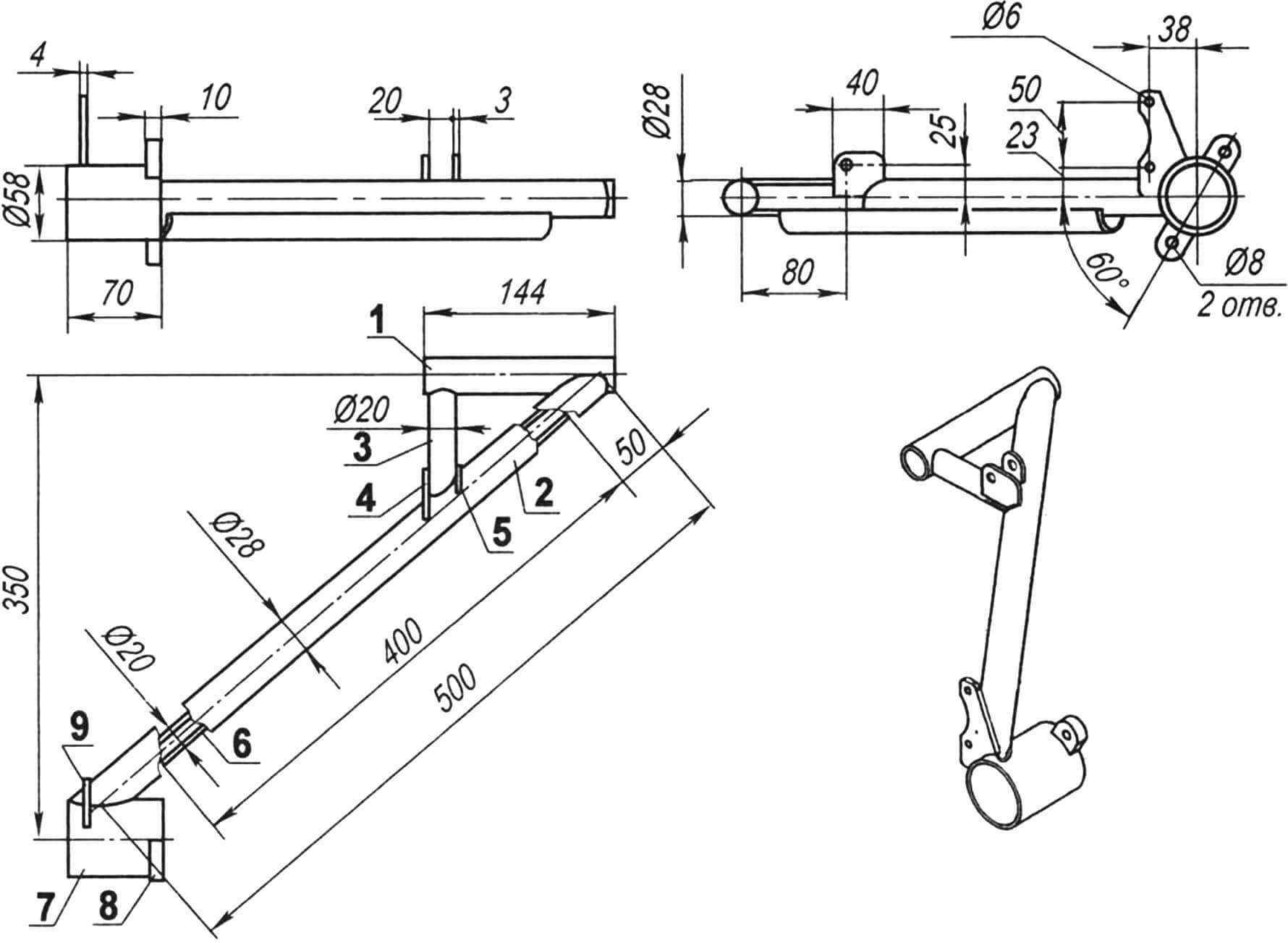
1 — roller sleeve of the lever (pipe 28×2); 2 — lever (pipe 28×2); 3 — strut (pipe 20×2); 4 — large bracket for shock absorber attachment (sheet s3); 5 — small bracket for shock absorber attachment (steel sheet s3); 6 — lever reinforcement (longitudinal half of pipe 20×2); 7 — motor sleeve (pipe 58×2); 8 — bracket for motor attachment (sheet s10, 2 pcs.); 9 — bracket for brake caliper attachment (sheet s4)
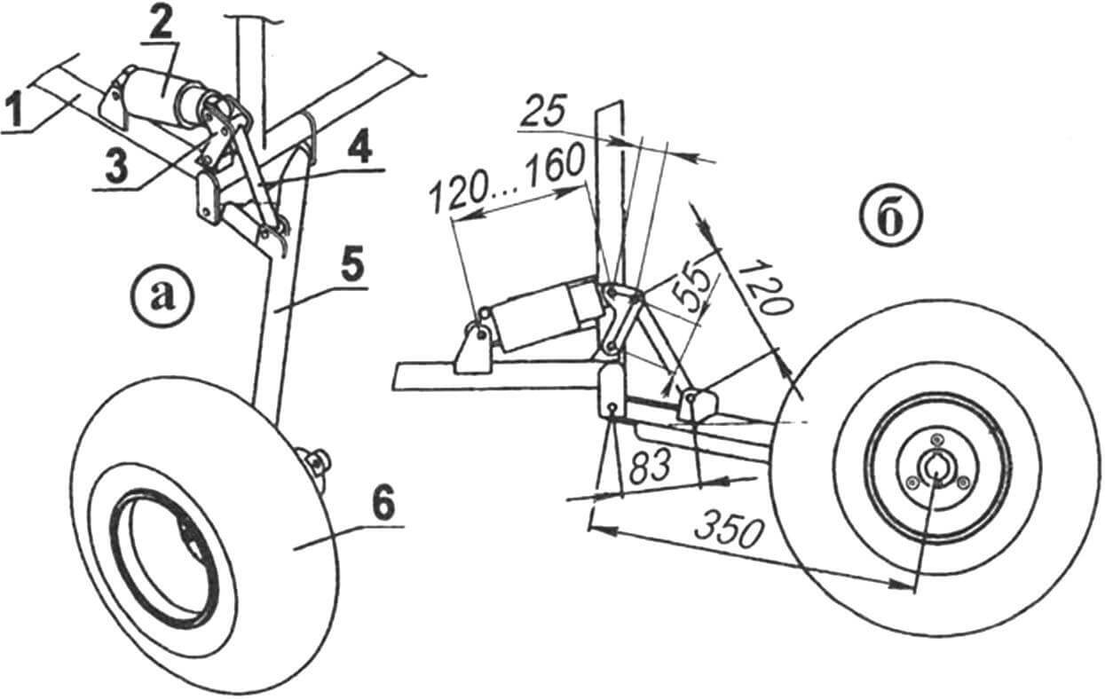
1 — frame; 2 — shock absorber; 3 — rocker arm; 4 — thrust; 5 — lever; 6 — wheel
The paramotor’s air screw, with a diameter of 1450 mm and a pitch of 500 mm (initially wooden, now fiberglass), provides a flight on a paraglider at speeds up to 100 km/h. The screw guard is standard, purchased together with the power unit.
The engine starting system components, including the battery, its charging relay, the starter relay and button, and the ignition key (ground switch), are located in a small box to the left of the pilot’s seat. By the way, the seat itself is anatomical, with shoulder seat belts.
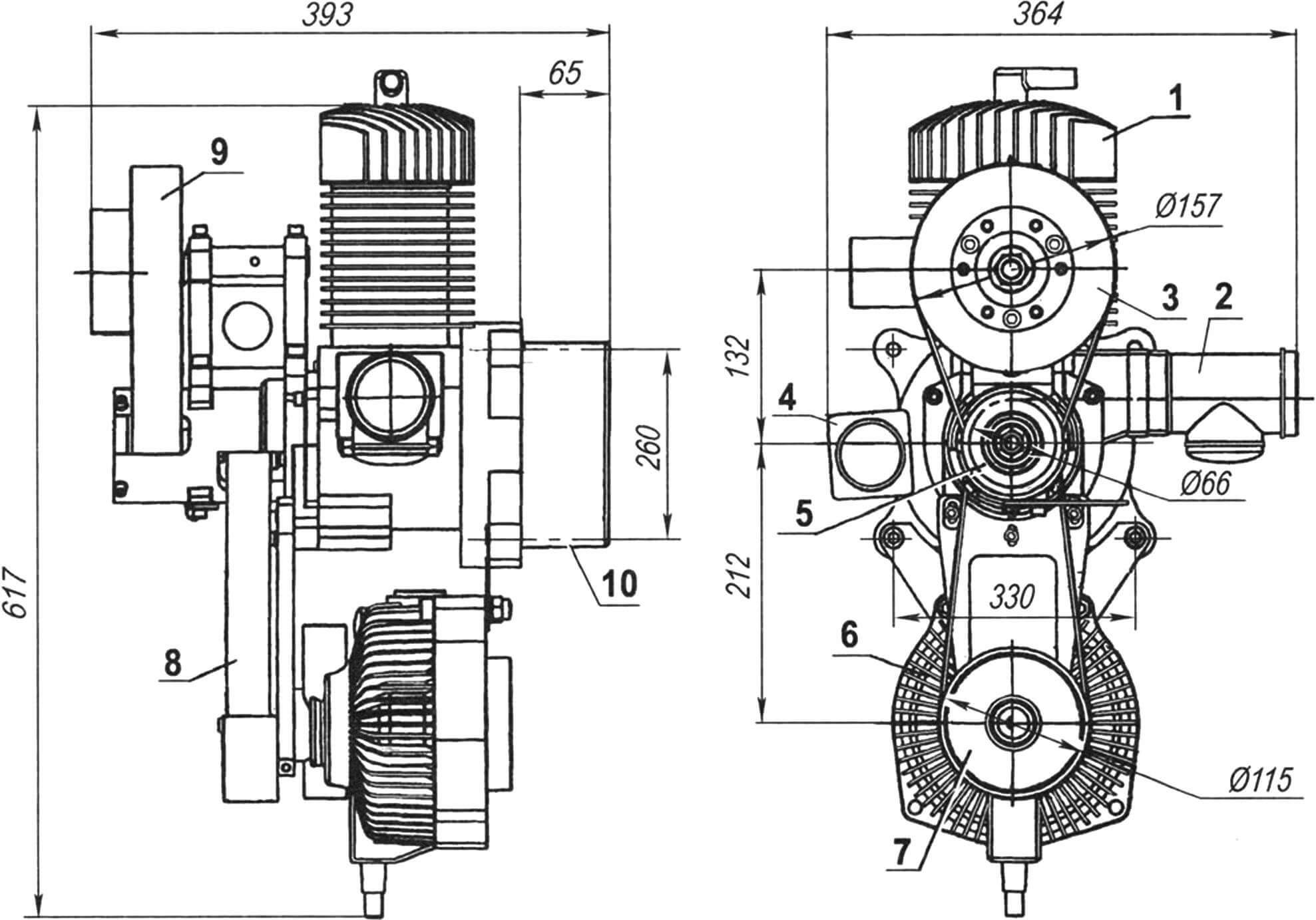
1 — engine cylinder; 2 — muffler; 3 — driven (drive) pulley of the propeller shaft; 4 — switch: propeller — hydraulic cylinder (wheels); 5 — driving pulley of the engine shaft; 6 — hydraulic pump; 7 — driven (drive) pulley of the hydraulic pump shaft; 8 — hydraulic pump drive belt; 9 — drive belt of the propeller shaft; 10 — engine crankcase
As mentioned earlier, the control elements of the cart, except for brakes and the engine starting system, are concentrated on the control lever-handle. On it, there is also a removable engine control handle mounted on the right side of the pilot’s seat. By moving the lever left and right, the front wheels turn, and moving it forward and backward from the neutral position engages the front or rear drive of the cart, respectively. Further movement of the lever increases the oil flow to the hydraulic motors, thereby increasing the speed of the cart.
On the removable handle, there is a throttle lever and an engine stop button. In flight, the curved control lever of the cart is fixed in the neutral position, and the pilot holds the handle in one hand in a comfortable position.
In the initial version, the cart did not have control instruments; they were installed later, along with the fairing (replacing the shield) on its front panel. There are three control instruments: the right one is a fuel level indicator in the gasoline tank, the middle one is an altimeter, and the far left one is an engine monitoring device: cylinder head temperature and exhaust gas temperature.
V. UVAROV
Recommend to read
 SPINNING WHEEL, BUT NOT GRANDMA
Times of shortage, it would seem, were but a grandmother for her grandchildren the old-fashioned way tend to knit warm clothes, especially socks and mittens. The best material for these... With a bicycle — even in the metro
In recent decades, the world has been experiencing a bicycle boom. Today, the bicycle is the number one means of transport on the planet, and even the car yields the palm: for every...
