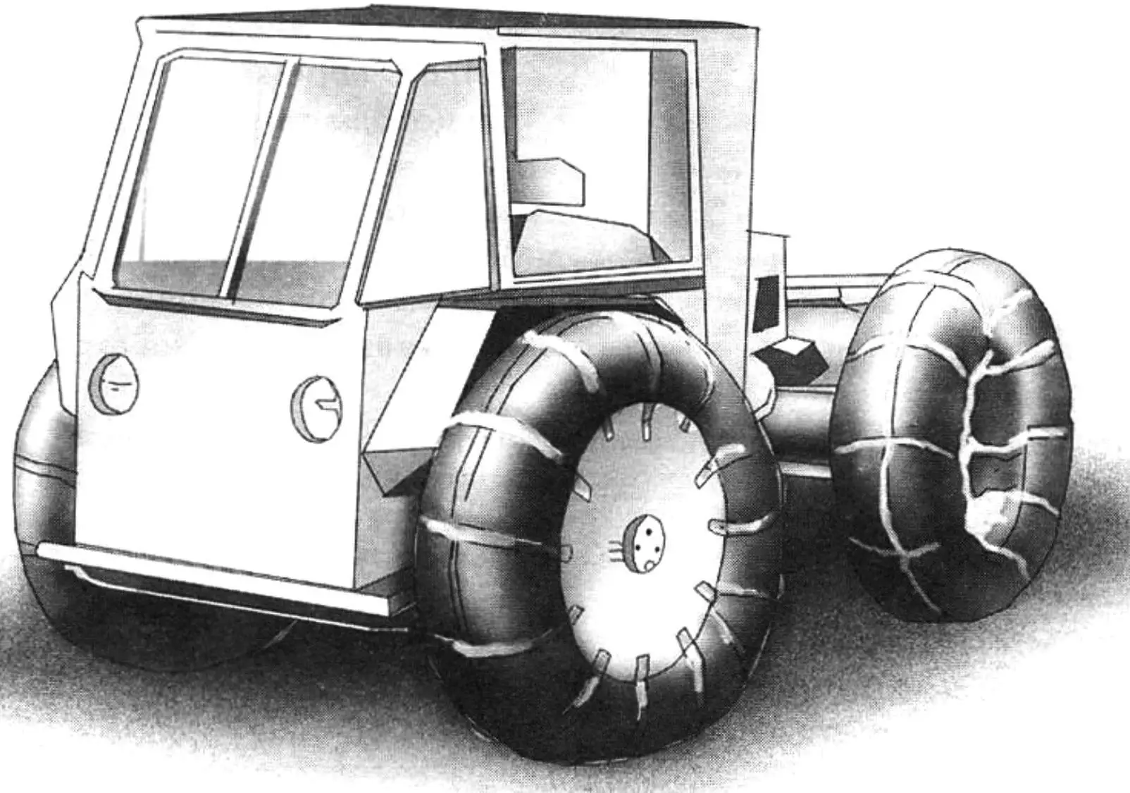
When designing this all-terrain vehicle, amateur designer L. Antokhov from the town of Kirishi in the Ryazan Region aimed to create an all-season, reliable and highly traversable machine with small dimensions and mass, fitted with a closed cabin for three people — a driver and two passengers. The result of the work was an ATV on ultra-low-pressure tires with a “4×4” wheel formula, built to the layout of a vehicle with an articulated (“breaking”) frame and featuring an original transmission.
During the first year and a half of operation the machine covered more than three thousand kilometers, and the designer had no significant remarks regarding the ATV’s strength, reliability, handling or cross-country ability.
The machine has a low curb weight — about 220 kg — and can carry three people and 50 kg of cargo in the trunk. It can also tow a trailer (its mass with cargo is 250 kg). In addition, this vehicle easily fords water obstacles. Worth mentioning is also the self-recovery winch fitted to the ATV: the tractive effort it develops (about 1 t) allows the machine to get out of practically any off-road predicament.
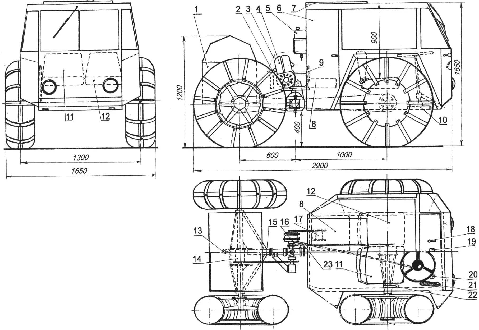
1 — trunk; 2 — muffler; 3 — engine cover; 4 — engine from an S3D motorized wheelchair; 5 — fuel tank; 6 — door; 7 — roof hatch; 8, 12 — passenger seats; 9 — engine starter handle; 10 — steering gear housing; 11 — driver’s seat; 13 — towing hitch; 14 — rear axle differential; 15 — chain drive to the rear axle; 16 — chain drive to the front axle; 17 — self-recovery winch; 18 — shift lever; 19 — clutch pedal; 20 — brake pedal; 21 — carburetor throttle pedal; 22 — gearbox shift lever; 23 — steering rod
It should also be noted that the ATV is easily transformed into a tractor: one only needs to replace the ultra-low-pressure tires with ordinary tires of 650 to 800 mm outer diameter and install on the engine output shaft a new sprocket with 12 to 14 teeth. The microtractor’s speed then does not exceed 35 km/h.
The ATV’s transmission consists of three chain drives, a reverse gearbox with a transmission brake, a transversely arranged propeller shaft with a flexible coupling, and two differentials (front and rear axles).
Torque from the engine is transmitted through a sprocket (z = 12…19) to the reverse gearbox by a roller chain. The sprocket hub on the reverse gearbox serves as a brake drum; the brake shoes are mounted on the reverse-gearbox flange.
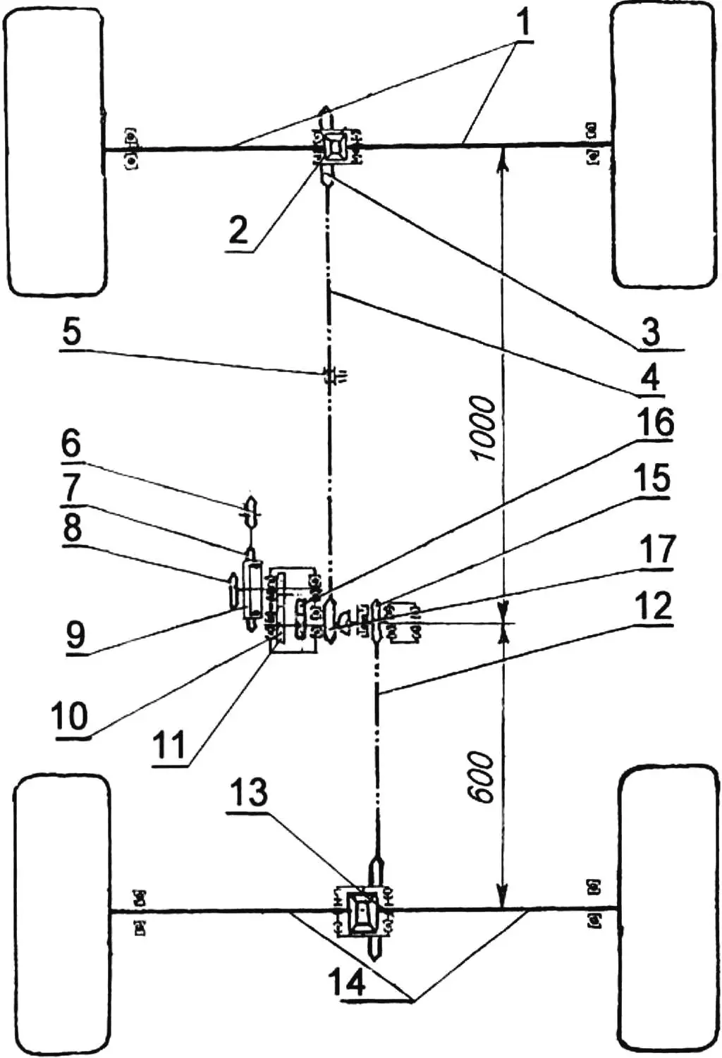
1 — front half-shafts; 2 — differential (from a Moskvich car); 3 — differential sprocket (z = 40); 4 — front-axle drive chain; 5 — idler roller; 6 — engine output shaft sprocket (z = 16); 7 — primary sprocket of the reverse gearbox (z = 31); 8 — reverse-gearbox PTO shaft sprocket (z = 13); 9 — transmission brake drum; 10 — forward-gear pinion (m = 3, z = 23); 11 — forward-gear pinion (m = 3, z = 18); 12 — rear-axle drive chain; 13 — rear axle differential; 14 — rear axle half-shafts; 15 — propeller shaft sprocket (z = 13); 16 — reverse-gearbox idler gear (m = 3, z = 18); 17 — reverse-gearbox output shaft sprocket (z = 13)
On the reverse-gearbox output shaft are mounted a sprocket (z = 13) for the front-axle drive and also a propeller-shaft yoke. The second propeller-shaft yoke is connected via an intermediate shaft to a flexible coupling that compensates for axial movement of the propeller shaft when the frame “breaks” on turns and also damps shock loads arising in the transmission. The other end of the coupling is fitted on the shaft splines together with a sprocket (z = 13) for the rear-axle drive.
The propeller shaft runs inside a 100×100 mm opening of the steering joint. The axis of rotation of the propeller shaft must coincide exactly with the point formed by the intersection of the vertical axis of the steering joint and the horizontal axis of axle “rocking” relative to each other. This operation is rather complex, but it can be somewhat simplified by replacing, during assembly, the propeller shaft with the coupling by a 50 mm diameter mandrel with two transverse holes 20+0.1 mm in diameter (for the vertical axis of the steering joint) and 15 mm in diameter (for the axle rocking axis), located at 90° to each other, exactly on the mandrel’s axis of rotation at the propeller-shaft break point. On this mandrel the reverse gearbox and the shaft with the bearing housing and bracket are assembled. After inserting a 15 mm round rod into the rear propeller-shaft yoke along the axle rocking axis and assembling the steering joint on a 20 mm rod that passes through the mandrel hole, the reverse gearbox must be welded to the front fork of the steering joint, and the bracket welded to the rear-axle frame tube through an intermediate adapter plate.
Now the mandrel should be replaced with the propeller shaft and coupling, and the 20 mm rod with two pins, and the smoothness of propeller-shaft rotation should be checked at various steering angles and axle rocking angles. The reverse gearbox was designed by L. Antokhov himself. Its housing is made of two parts. For their mutual mating and centering, a recess is machined in the gearbox cover and a matching projection on the housing itself.
Work begins with turning the cover and housing on a lathe to finished outer dimensions. Inside, only a preliminary bore is made first, so that the end-wall thickness is 12…15 mm. Such thickness is needed so that the housing is less distorted during welding. Then the cover and housing are bolted together with M8 bolts, after which the shaft axes are marked on the end face of the housing and holes are drilled for the bearing housings of the reverse shift rod and the reverse idler gear shaft. This operation is best done on a milling machine with center distances verified against the machine dials.
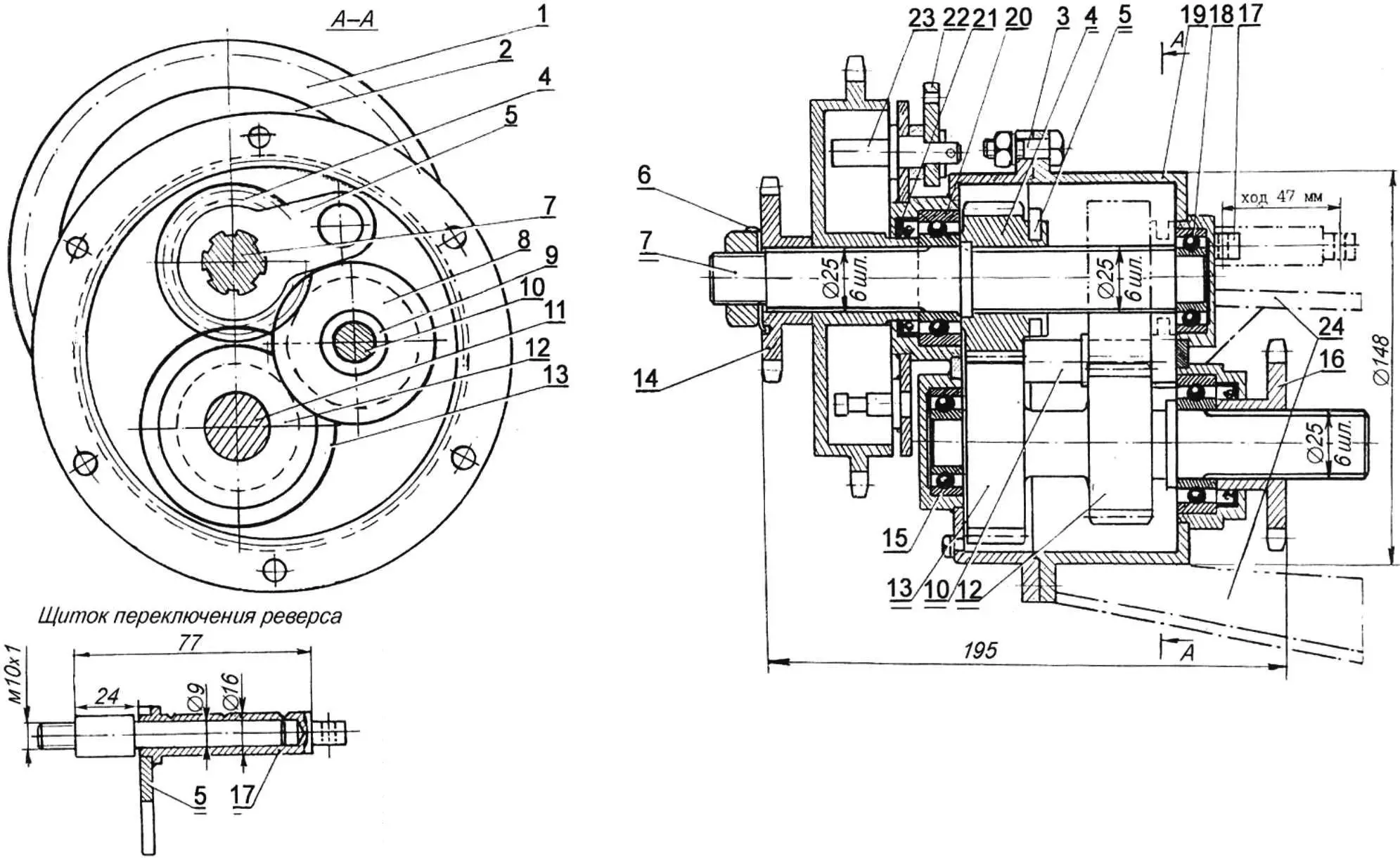
1 — sprocket (z=31); 2 — brake-shoe mounting flange; 3 — M8 bolt with nut and washer; 4 — primary-shaft gear (m=3, z=18); 5 — reverse-gearbox shift fork; 6 — washer; 7 — primary splined shaft; 8 — idler gear (m=13, z=18); 9 — idler gear bushing; 10 — idler gear shaft; 11 — reverse-gearbox secondary shaft; 12 — gear (m=3, z=18); 13 — gear (m=3, z=23); 14 — sprocket (z=13); 15 — bearing 1203; 16 — sprocket (z=13); 17 — reverse shift rod; 18 — bearing 203; 19 — housing; 20 — bearing 205; 21 — oil seal 46x32x10 mm; 22 — brake lever; 23 — brake cam; 24 — reverse-gearbox mounting brackets
The bearing housings, reverse shift-rod lock, brake-shoe flange and gearbox-to-frame mounting parts are welded to the housing and cover. After welding, the M8 bolts fastening the cover to the housing are removed and the inside of the housing is machined to the final dimensions. The final end-wall thickness should be 4…5 mm — that is quite enough. Threaded holes are cut in convenient places of the housing and fitted with threaded plugs — they are needed for changing oil in the gearbox.
The reverse-gearbox gears and shafts are made of 40Kh steel with subsequent heat treatment.
The ATV frame consists of two hingedly connected half-frames, each built from a 60×3.5 mm steel tube welded to the corresponding axle. The frame has four detachable joints: two of them provide transmission chain tension, the third is the steering joint, and the fourth is the axle rocking joint.
The steering joint is assembled by welding from parts cut from 6…8 mm steel plate. The joint forks are connected by 20 mm diameter pins passed through No. 204 bearings.
To give the rear half-frame greater rigidity, the rear axle is additionally braced relative to the longitudinal half-frame tube by two struts made of 20×1.5 mm tubes. On the front half-frame a closed contour is welded from 40×1.5 mm tubes, matching the cabin floor outline in plan.
The ATV’s front and rear axles are homemade. The bearing housings, differential and shortened half-shafts are from a Moskvich car. The differential housing is enclosed by a metal cover. The half-shaft is joined by a sleeve (hot press fit) secured to the half-shaft elements with electric rivets.
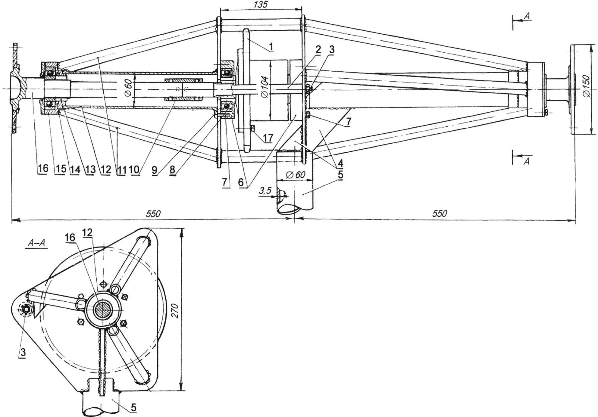
1 — sprocket; 2 — bushing (tube Ø20×1.5 mm); 3 — M10 stud; 4 — stiffening rib; 5 — frame; 6 — bearing housing; 7 — M8 bearing-housing bolts; 8 — bearing 207; 9 — differential housing; 10 — half-shaft joining sleeve (secured with electric rivets); 11 — struts; 12 — half-shaft tube (tube Ø60×1.5 mm); 13 — bushing; 14 — oil seal; 15 — bearing housing; 16 — half-shaft; 17 — M10x1 bolt
The ATV engine is from an S3D motorized wheelchair. It is mounted above the reverse gearbox and steering joint on the front half-frame, with the cylinder facing rearward. Chain tension between the engine output sprocket and the reverse-gearbox sprocket is adjusted with shims. Among the shim pack a pair of 6 mm rubber pads is always used to isolate the frame from engine vibration.
The engine is started with a kick starter from the cabin. For easier cold-weather starting the carburetor is fitted with an additional choke.
To prevent carburetor and cabin-glass icing in winter, warm air from the engine cooling system is fed to the carburetor air filter and to the windshield through a 44 mm corrugated hose.
The ignition and electrical system are powered by a generator taken from an Elektron scooter engine. A magneto installation is also provided in case of emergency failure of the main ignition system.
In the right engine cover, coaxial with the crankshaft journal, a recess is machined in which an adapter flange is secured with four M6 bolts. The flange has three M5 threaded holes for mounting the generator base. The right crankshaft journal is turned to fit the flywheel from an Elektron scooter engine. The magneto is mounted on the left side of the engine.
The motor is enclosed by a 1 mm duralumin sheet cover.
Operation has shown that the engine power is quite sufficient for travel on roads, crusted snow and ice at up to 60 km/h, and through deep loose snow at up to 35 km/h.
The machine’s steering gear is a rack-and-pinion unit from an S3D motorized wheelchair. Rack travel is transmitted through a ball joint to a 25×2 mm steel tube rod and then to a fork and bracket mounted on the rear half-frame in the plane of the steering axis. Steering stops allow one half-frame to deflect relative to the other by 30° left and right. The control system and machine design provide a turning radius of 3 meters; the machine handles well and is sufficiently directionally stable.
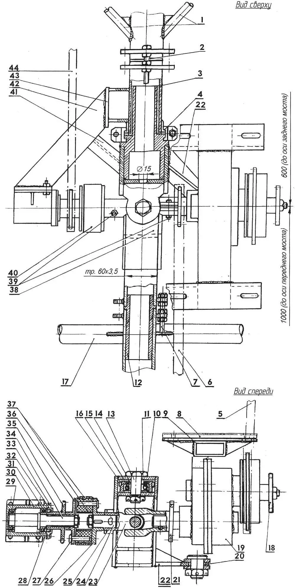
1 — rear axle struts (20×1.5 mm tube); 2 — M10 bolt; 3 — bushing; 4 — clamp; 5 — reverse-gearbox drive chain; 6 — front-axle drive chain; 7 — chain tension adjuster; 8 — rubber gasket; 9 — rectangular tube for engine mounting; 10 — cover; 11 — bearing 204; 12 — chain tension bushing; 13 — steering joint pin; 14 — spacer washer; 15 — rear axle fork; 16 — bearing housing; 17 — frame tube; 18 — PTO shaft sprocket (z=13); 19 — reverse gearbox; 20 — bushing; 21 — sprocket (z=13); 22 — steering-rod bracket; 23 — universal joint; 24 — shaft; 25 — U-joint yoke; 26 — half-coupling; 27 — pin; 28 — M6 bolt; 29 — bearing No. 204; 30 — bearing housing; 31 — bearing No. 205; 32 — oil seal; 33 — cover; 34 — splined shaft; 35 — sprocket (z=13); 36 — half-coupling; 37 — coupling band; 38 — front axle fork; 39 — M8 bolt; 40 — flexible coupling; 41 — axle tilt stop; 42 — bracket (60×30 mm rectangular tube); 43 — plate; 44 — rear-axle drive chain
The controls are of automotive type. The carburetor throttle drive is combined: by cable and a 4 mm rod; the other controls use rigid rods through ball joints. All rods run along the central frame tube close to the chain drive. This arrangement makes it possible to cover the transmission and rods with removable guards.
As already mentioned, the cabin base is a 40×1.2 mm steel tube welded to the front axle and the central tube of the front half-frame. Vertical posts of 15x25x1.2 mm steel angle are welded to this same tube, welded to the front axle and the central tube of the front half-frame. Vertical posts of 15x25x1.2 mm steel angle are also welded to this same tube; cabin panels of 3 mm waterproof plywood and 1 mm sheet-aluminum mudguards are riveted to them. Cabin glazing is combined: windshields are tempered glass (“stalinite”) from a written-off bus; side and rear windows are 3 mm acrylic. The roof is covered with canvas, and a 0.5 mm aluminum panel is fixed over it. The door and hatch are frames of duralumin tubes covered with canvas.
The seat backs, and the entire rear seat, are folding — this is done for easier entry and exit.
The self-recovery winch is located under the folding seat. To operate it, the reverse gearbox is set to neutral, after which the reverse-gearbox PTO sprocket (z = 13) is connected by a roller chain to the winch sprocket (z = 29). Then the winch cable is paid out and secured, the clutch is disengaged, first (or any other) gear of the engine gearbox is selected and the clutch is engaged. The winch drum then starts to rotate. If necessary, the winch can be stopped with the transmission brake.
“Modelist-Konstruktor” No. 11’2010, L. ANTOKHOV
Recommend to read
 UNDER SAIL OR MOTOR
The motor-sailing vessel (SMS), which will be discussed, was built on the basis of the finished hull of an existing model of a torpedo boat, made on a scale of 1:4. I got the hull of the... THE “WORKHORSE” OF THE BRITISH ARMY
In 1966, the military command of the British army felt that the troops needed a new car a solid class that would be easier and on dimensions less than the then car firms "Austin",...
