
The proposed design is a five-section three-seat boat with a carrying capacity of 320 kg. On tourist trips, once hauled ashore, it turns into a fairly spacious “tent,” especially if a piece of polyethylene film is thrown over the top. The boat is so simple that even a person unfamiliar with boatbuilding and having only the most elementary woodworking skills can make it. No special equipment or premises are required for manufacture; the entire boat is assembled in a room of a city apartment. It is made from widely available materials that can be purchased in building and hardware stores. The cost is approximately 20—30 rubles (it should be noted in passing that for boat registration one must keep all receipts and invoices from the stores).
The choice of dimensions (3.3X0.98X0.32) is dictated by the need to carry the “Crab” on a roof rack and by the desire to make the craft suitable for a wide variety of voyages by a group of 2—3 people.
The boat is designed as a rowing craft, but thanks to the reinforced transom it can be fitted with a demountable sail of 3.5 m2 area or an outboard motor of the “Salyut” type.
The hull consists of five compartments — “boxes” — which, when assembled, are joined and tightened with a steel cable. Sideways shifting of the sections is prevented by projections and sockets in the side stringers (gunwales). This design makes it possible to assemble the boat in a shortened two-seat version: the middle (third) section is not installed, and a shorter tensioning cable is used.
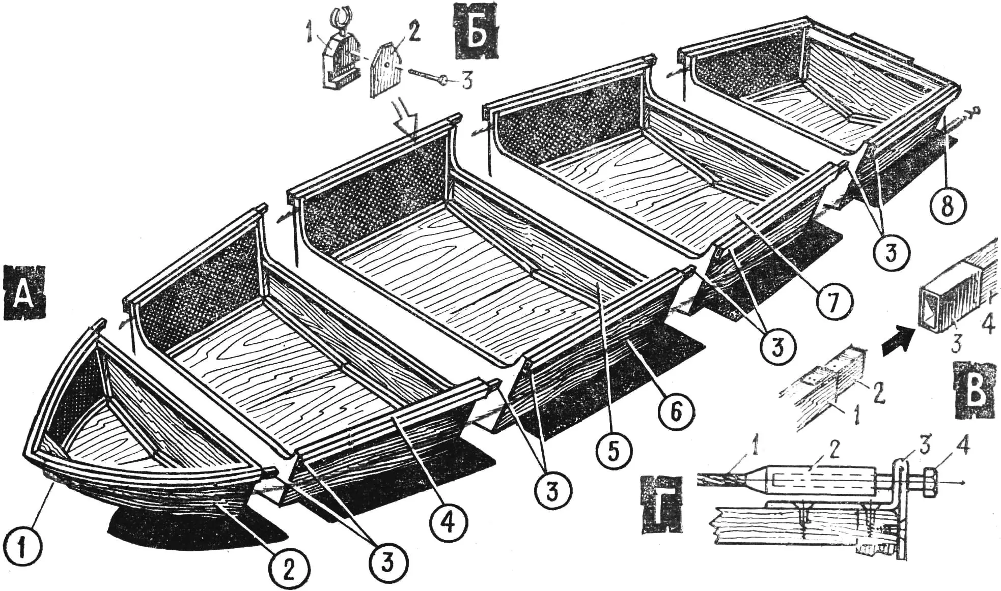
A — hull (shown disassembled): 1 — tensioning cable, 2 — bow section, 3 — joints of the outer gunwale, 4 — inner gunwale, 5 — end bulkhead (diaphragm), 6 — side planking (3 mm plywood), 7 — bottom planking (4 mm plywood), 8 — tensioning device. B — oarlock mounting: 1 — oarlock socket, 2 — pad, 3 — clamping bolt. C — construction of the outer gunwale joint: 1 — gunwale, 2 — tenon, 3 — socket (roofing iron), 4 — gunwale of the next section. D — cable tensioning device: 1 — cable, 2 — threaded bushing, 3 — bracket, 4 — tensioning bolt.
The bottom stringers are fitted on the outside of the boat — this creates a keel effect, which improves the boat’s directional stability.
The rise of the bow and stern, provided by a slight inward cant of the joined sections (by 4—5 mm) during fitting, significantly improves seakeeping.
Construction should begin with making paper patterns of all side, bottom, and bulkhead plywood parts. After that, the plywood is cut out, bearing in mind that all pieces must be cut along the grain of the outer plies (faces). A small allowance is left for trimming the ends. Side and bulkhead parts are cut in pairs. Then battens for the longitudinal and transverse framing are cut. The blanks should be marked with double numbering: the first digit is the section No., and the second is the part No. (for example, 3—11, 45, etc.). Using the patterns, the exact outline and the glue locations for the framing members (battens) are marked in pencil. Both surfaces are coated with glue and the battens are pressed against them. Joints are made half-lapped. To keep the corners from slipping, they are temporarily tacked with small nails (not driven all the way in). Immediately, before the glue sets, the side is turned over and from the plywood side the battens are secured with 10X2 screws in a “snake” pattern at 50—60 mm spacing.
Blanks for the internal bulkheads and the transom are made in exactly the same way.
For the bow section, straight battens cannot be used — they are made laminated from plywood. For this, 16 narrow (30—32 mm) plywood strips 650 mm long are cut. On a thick board measuring 700X200 mm, full-size outlines of the upper (gunwale) and lower (chine stringer) battens are drawn. Along the outline, 75-mm nails are driven to a depth of 15—20 mm. Then the strip blanks are coated with glue and inserted into the jig formed by the nails. To pull the strips more tightly together while drying, twine is zig-zagged near the tops of the nails. The second pair of blanks is glued in the same way. The edges of the glued blanks are finished with a file and sandpaper.
The stem (bow timber) is hewn from an oak bar. Recesses are cut in it for fastening the ends of the gunwales and chine stringers. Then the chine stringers, stem, and bow bulkhead are joined with glue and screws, and the top of the stem is tied to the top of the bulkhead with a temporary batten on screws. After that, the side blanks are immediately fitted with glue and screws, and the gunwale blanks are “clamped” over them from above. The symmetry of the whole structure must be checked.
A day later, when the glue has “set,” the bottom and deck are laid on; an opening of 180X260 mm for the baggage hatch is cut in the deck beforehand.
Then, on a sheet of paper (preferably graph paper), squares one inside another and the outline of the bow section are drawn to match the dimensions of the upper part of the future boat’s section — this will make gluing the sections easier and avoid the need to correct skew.
On the floor, on a paper sheet used as a template, all sections are assembled with glue and screws — first the sides and bulkheads, then the bottom sheets. After that the gunwales (with tenons and sockets) are fitted and installed, and the boat is temporarily assembled on tie bolts and finished with a file and sandpaper. This operation should be done twice.
All sections and the blanks for the bottom stringers are twice impregnated with hot drying oil and, after the second impregnation, left for 4—5 days. The dried sections are lightly cleaned with sandpaper and assembled together once more for a final check of all joints. Then the sections are wiped on the outside with a swab moistened in gasoline or white spirit to degrease the surface.
Next, the bottoms of all five sections are covered with glass cloth on epoxy adhesive with 10—15% acetone added as a thinner. The edges of the cloth are turned up and run onto the sides for 50—80 mm. At the same time, all external corners of the sections are reinforced with narrow strips — offcuts of glass cloth — on the same epoxy adhesive. Immediately, before the resin sets, the bottom stringers, coated with the same adhesive, are laid on the bottom and secured with 15X3 screws at 80—100 mm spacing.
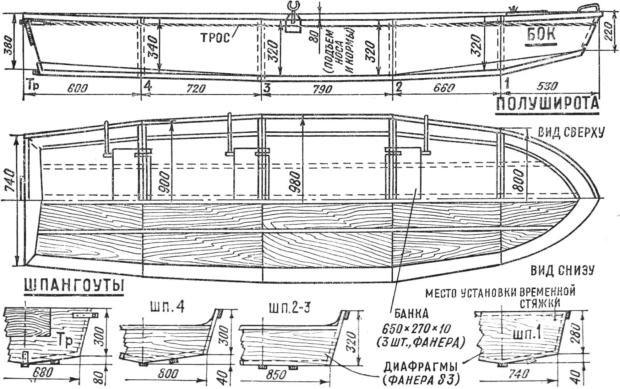
Two days after the resin has cured, the boat is again finished with sandpaper (especially at the edge of the glass cloth) and then painted with the first coat of paint. After the paint has dried, all metal parts are installed, the tensioning cable is run, and the seats (thwarts) and hatch cover are fitted.
The oarlock holders are made by riveting pieces of duralumin of suitable thickness. As a last resort — from oak or beech with a steel strip ferrule.
The oars (demountable, sculling) are made from three shovel handles, aluminum tubes of suitable diameter that fit tightly one into another, and aluminum blades measuring 150X400X1.5 mm.
It is desirable to make light floorboards for the second, third, and fourth sections, matching the section length and about 400 mm wide. They are made from 10X15 mm battens at 25 mm spacing, joined by three narrow transverse duralumin strips.
The cable is secured by a loop in the tensioner at the keel point of the transom; it then runs on both sides of the keel stringer to the stem; on the stem it is crossed twice in grooves under a pad and returns to the stern along the sides under the gunwale; the cable ends are secured in turnbuckles — tensioners — at the upper corners of the transom.
Building the boat will take approximately 150—200 hours (this depends on the amateur’s woodworking “skill”).
“M-K” 8’77, I. MALEVICH
Recommend to read
 SAFE POWER SUPPLY
The inclusion of transformers on 400 Hz network, 220 V(50 Hz) using a ballast capacitor. If you look at the merits in diversity of industrial and self-made Amateur radio power supplies,... “Shmel” glider-gyroplane
When designing and building the “Shmel,” the creative team “Vzlet” took as a basis the micro autogyro designed by V. Barkovsky, V. Vinitsky, and Yu. Rysyuk, described in detail in “M-K”...
