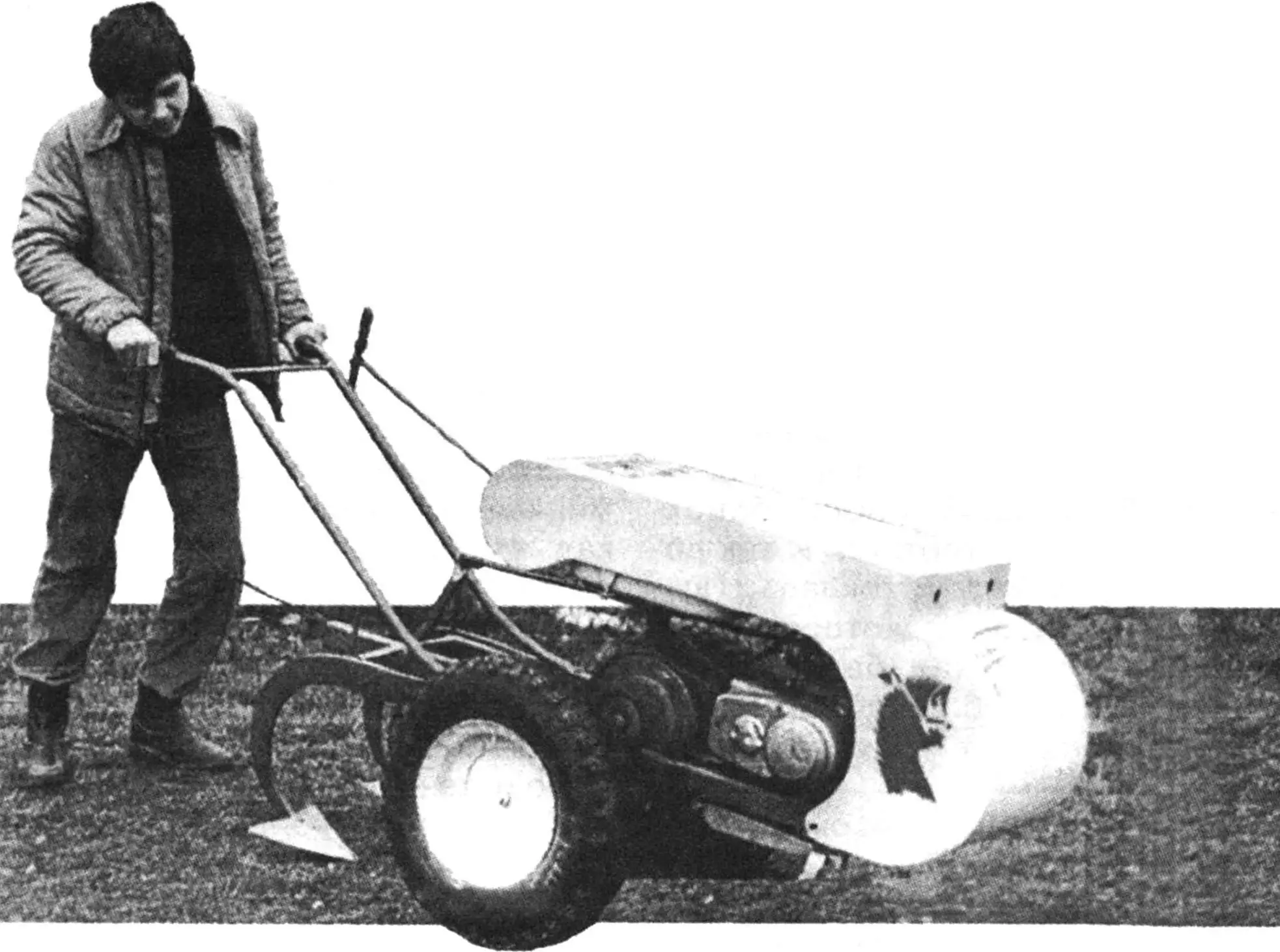
In gardens and vegetable plots, at dachas and school grounds — everywhere where there is a need to cultivate small areas of land, universal walk-behind tractors (UWT) are widely used. Including homemade ones, often created with maximum use of standard units and parts. One such design was developed and successfully tested by young technicians at the Youth Technical Station under the guidance of V. Konstantinov.
The compact (1700x900x840 mm assembled with handles) 140-kg agricultural machine, given the sonorous name “Kirpi” by its creators, performs four operations: plowing, harrowing, cultivation, and hilling of row crops. And when coupled with a single-axle trailer, it can also serve for local transportation of loads weighing up to 200 kg at speeds from 2 to 40 km/h. Such a walk-behind tractor is simple to manufacture, and accessible to operate even for a schoolchild. In one hour at a speed of 2 km/h, “Kirpi” plows an area of 0.05 hectares. Replacing the plow with cultivators or another working implement takes only two to three minutes, as they are attached to the UWT frame with just a few M10 bolts.
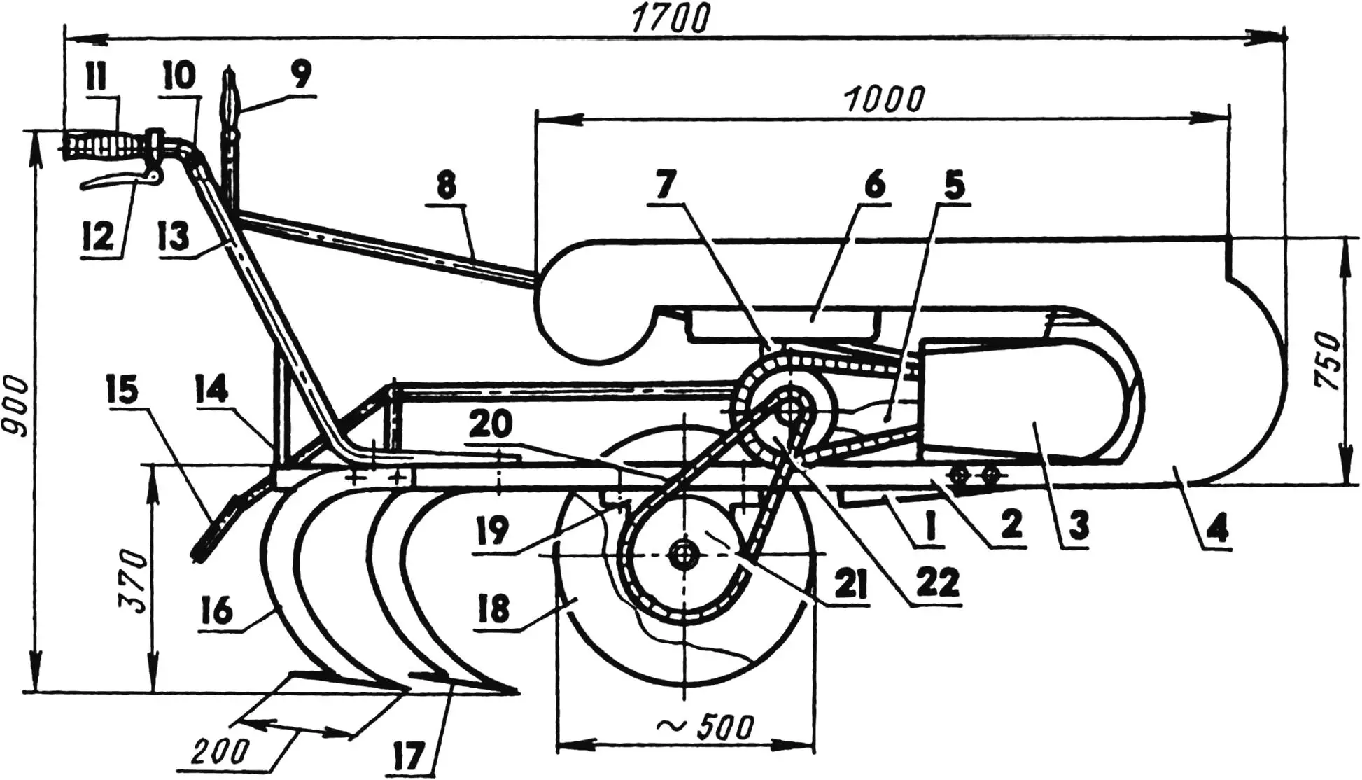
1 — folding footrest (from “Voskhod” motorcycle); 2 — frame (steel, tube 60x50x2); 3 — power unit (from “Minsk” motorcycle); 4 — hood (steel, sheet s2); 5 — muffler; 6 — fuel tank (from SZD motorized carriage); 7 — bracket (steel, tube 60×2.5 with two welded crossbars from 25×25 angle iron); 8 — gear shift lever rod (steel, rod Ø10); 9 — gear shift lever; 10 — crossbar (steel, tube 25×2, L600); 11 — throttle grip (from “Jawa” motorcycle); 12 — clutch lever grip (from “Jawa” motorcycle); 13 — control handle (steel, tube 33.5×4, L1200, 2 pcs.); 14 — brace (steel, tube 25×2, 2 pcs.); 15 — kickstarter lever with rod (steel, rod Ø10, L700); 16 — cultivator bracket-clamp (2 or 3 pcs.); 17 — cultivator blade (2 or 3 pcs.); 18 — wheel assembly (from SZD motorized carriage, 2 pcs.); 19 — output shaft bearing unit (from agricultural machinery, 2 pcs.); 20 — PR-19.05 chain (from agricultural machinery, 2 pcs.); 21 — output shaft sprocket with hub; 22 — intermediate shaft unit assembled with two intermediate sprockets
The kinematic transmission scheme is simple (and therefore reliable). From the power unit borrowed by the young technicians from the Youth Technical Station’s “Minsk” motorcycle, torque is transmitted to the intermediate shaft by a PR-19.05 roller drive chain with a driving sprocket z1 = 12 and driven sprocket z2 = 28.
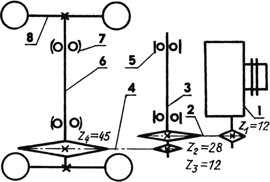
1 — power unit (from “Minsk” motorcycle); 2 — first stage of chain drive (i = 2.33); 3 — intermediate shaft; 4 — second stage of chain drive (i = 3.75); 5 — intermediate shaft bearing unit (2 pcs.); 6 — output shaft; 7 — self-aligning output shaft bearing unit (from “Niva” combine harvester straw walker, 2 pcs.); 8 — wheel (from SZD motorized carriage, 2 pcs.)
The second transmission stage is almost a copy of the first, only the number of teeth on the driven sprocket z4 = 45 (fortunately, they managed to find one in the Youth Technical Station’s inventory). As a result, the gear ratio of the intermediate gearbox increased from 2.33 to 3.75. The introduction of such a two-stage chain drive into the walk-behind tractor’s kinematics reduced the output shaft rotation frequency by 8.74 times.
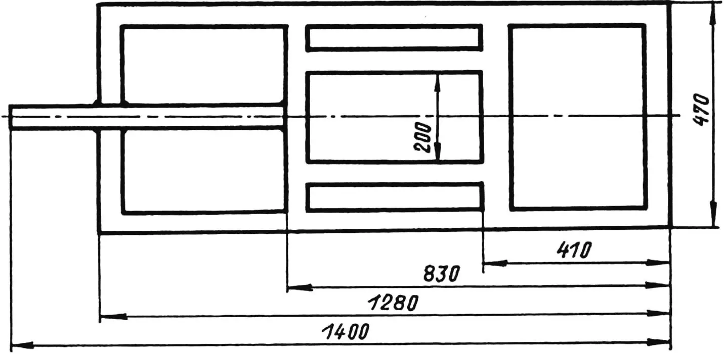
The walk-behind tractor frame is welded, made from 60x50x2 mm steel tube. In plan view, this structure resembles a window frame for glazing a balcony or loggia, but several times smaller. Overall dimensions are 1280×470 mm with a 120-mm extension for attaching a removable plow or third cultivator blade. On top, on small longitudinal cutouts, adapted bearing units (from scrapped agricultural machinery) of the intermediate shaft are mounted in place, and below on the sides — the output shafts.
The power unit is installed in the front part of the frame using two clamps (fitted in place), made from 2 mm thick steel strips. Two holes are drilled in the base of each clamp for M10 bolts.
The transfer shaft, sprockets, and chains of the two-stage torque transmission from the power unit to the UWT output shaft were borrowed, as noted, from automotive, motorcycle, and agricultural machinery that had exhausted its service life (but proved quite acceptable for “Kirpi”). The output shaft bearing units were also adapted from the “Niva” combine harvester straw walker.
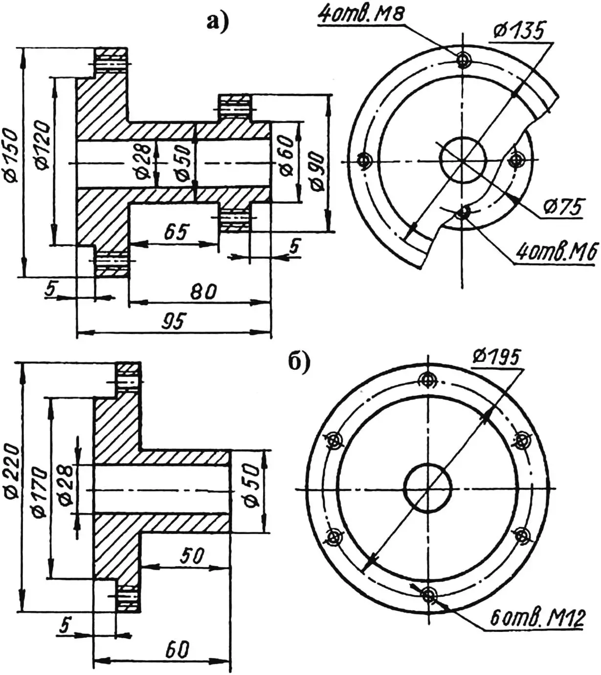
a — wheel; b — intermediate shaft sprockets
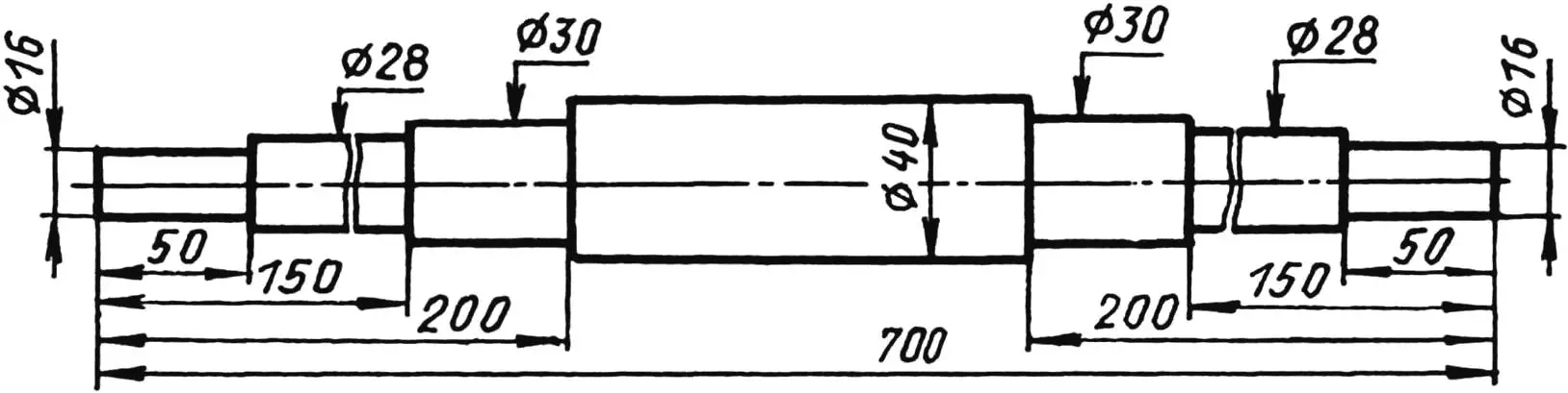
The output shaft, as well as the wheel and sprocket hubs, are homemade. Turned from steel 45. The technology for manufacturing and assembling hubs with sprockets was described in the pages of “Modelist-Konstruktor” (No. 5’91, 3’95, 2’97).
The wheels and fuel tank are from an SZD motorized carriage. The steering levers are made from thick-walled steel tube. The clutch lever and carburetor throttle control grips are from a “Jawa” motorcycle, the footrest is from a “Voskhod” motorcycle. The gear shift and kickstarter levers are made from 10 mm diameter metal rod.
The kickstarter is brought back to the operator, which facilitates the engine starting process. Fuel flows from the tank to the engine by gravity.
The hood material is 1.5 mm thick metal sheet.
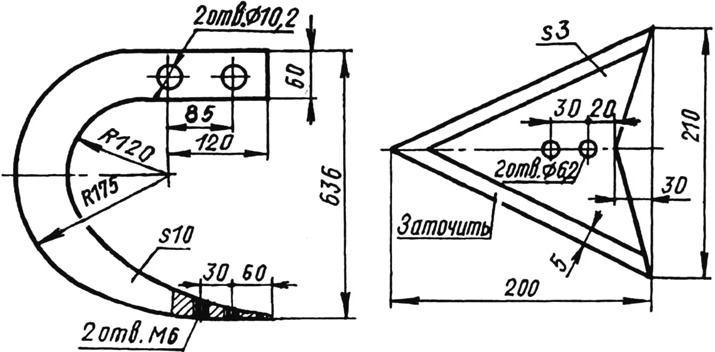
Despite the fact that the walk-behind tractor can perform several operations, the students most often use it on the school plot and in the collective farm garden as a cultivator. The working implements — cutting blades — are made of 3 mm thick stainless steel. They are attached to the walk-behind tractor frame using three steel clamps, each 10 mm thick, and bolted connections.
“Modelist-Konstruktor” No. 8’2001, N. KOCHETOV
Recommend to read
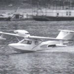 FLYING BOAT L-31
29.09.2012 G. has a new plane the boat under the designation L-31 and "New Faith." Now the aircraft has been tested in acquitting all the calculations and hopes. Manufactured flying boat...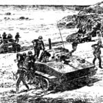 FROM THE WATER – FIGHT!
Few people of Leningrad, occupancies that August day in 1935, near the Peter and Paul fortress, the Neva river, witnessed the unusual spectacle. On the river, confidently slicing through...
