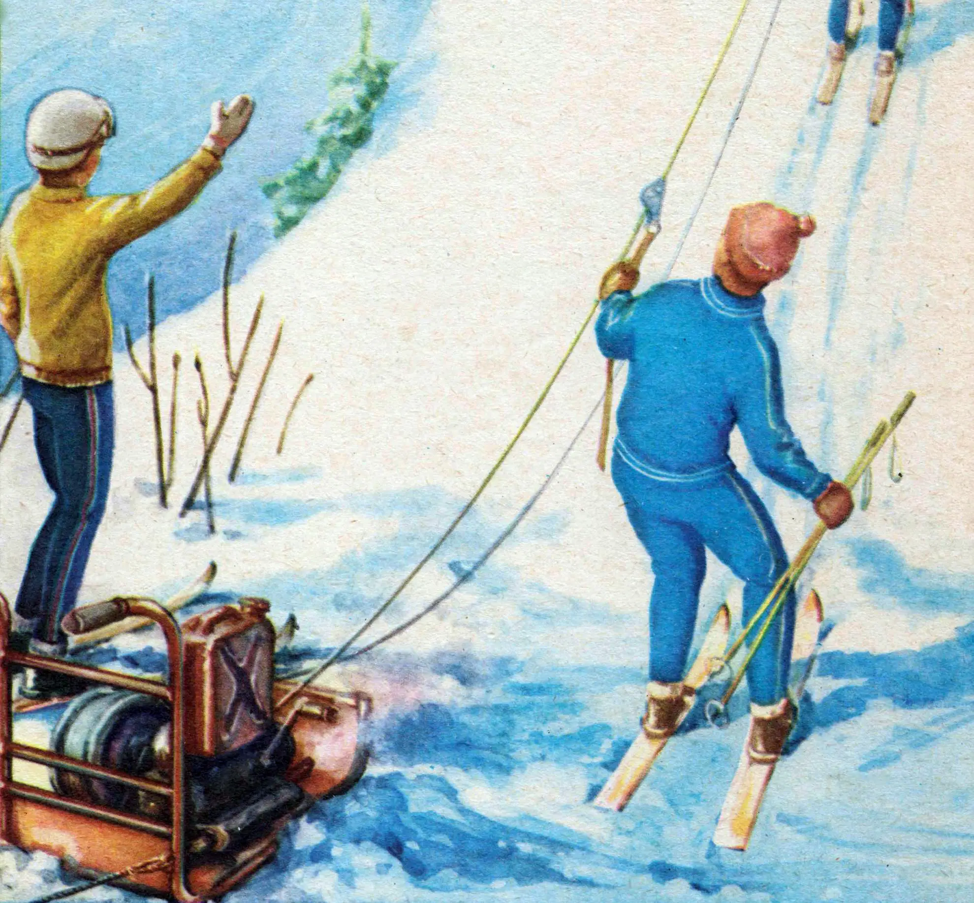
For tourists and skiers in “large” mountains with complex terrain and significant elevation differences, chairlifts are usually installed. On their traction-carrying cable, they have special suspensions with one or two chairs. The length of such lifts is limited to 1.5—2 km: experience has shown that an ascent exceeding 10—15 minutes in time can lead to problems in winter — frostbite of unprotected areas of the skin, especially the face.
As for the so-called “small” mountains, the most rational here is the use of a cableway with ski tows (T-bars). Such towing lifts are often designed by amateurs, using the most common materials and simple mechanisms. Despite their simplicity and unpretentiousness, they can lift up to 500—700 skiers per hour up a small slope.
We offer a description and diagram of a homemade portable lift that has proven itself well, working for several seasons on ski slopes.
The development of “small” mountain and ravine slopes by skiers is most conveniently started using compact cable “lifts” made using thin steel cable and two-stroke internal combustion engines. Such a lift can easily be brought to the skiing location, say, in the trunk of a car. Installation on the slope by 2—3 people takes no more than half an hour. And the operation of a cableway with a length of 150—200 m can be provided by a motor with a power of 6—12 hp.
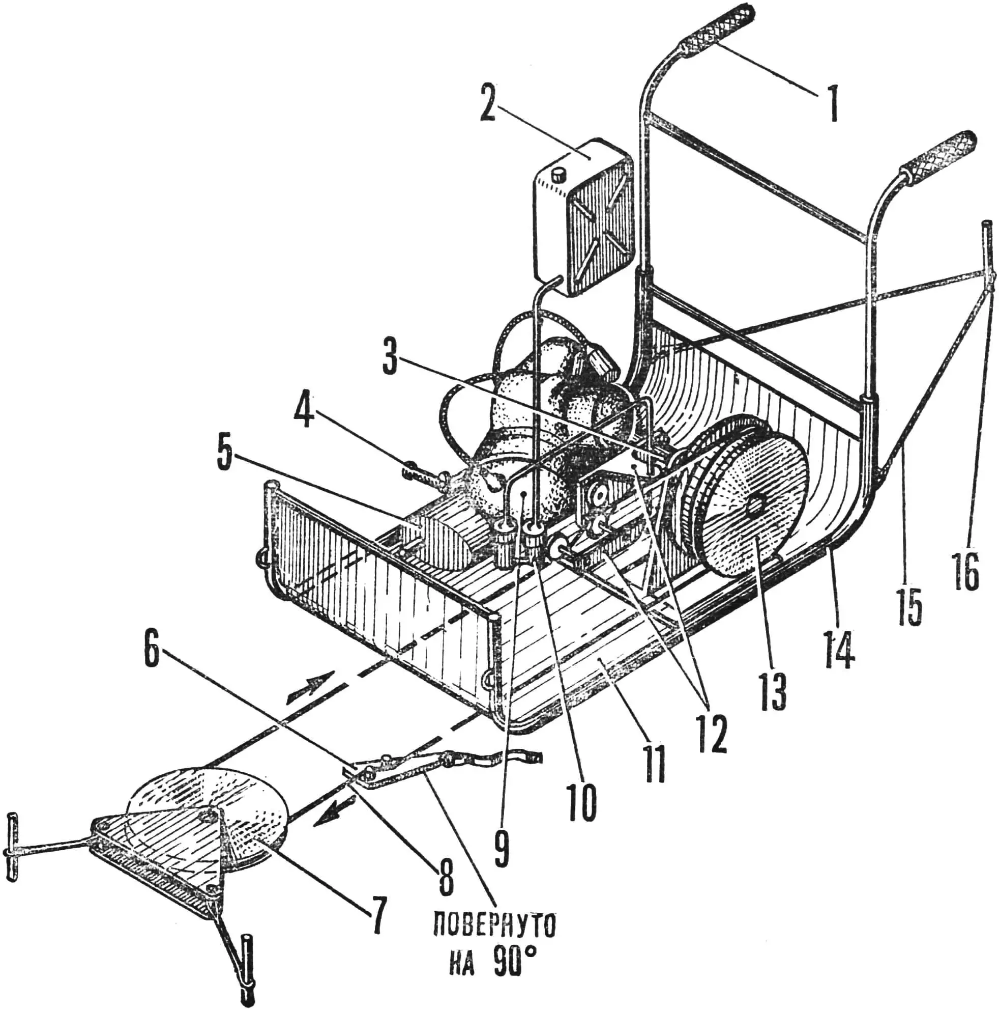
1 — frame-sled handle, 2 — fuel tank-canister, 3 — drive shaft, 4 — engine kickstarter, 5 — muffler, 6 — ski tow, 7 — return block, 8 — traction cable, 9 — engine, 10 — carburetor slide chamber, 11 — frame-sled bottom sheathing, 12 — throttle control, 13 — drive pulley, 14 — lift frame-sled, 15 — guy cable, 16 — stake.
Most suitable for this purpose are engines from scooters “Vyatka” — VP-150M, “Tula” — T-200M. Their undeniable advantage is the presence of a gearbox that allows changing the speed of the traction cable, and therefore the skier climbing the slope. It should only be borne in mind that all engines must have a forced cooling system.
The VP-150M engine, for example, is easily installed on a frame-sled with aluminum sheet sheathing on the bottom (Fig. 1), and since it is a so-called “motor-wheel” unit, the drive pulley of the lift is simply mounted on the axle instead of the removed wheel. The fuel canister is placed above the carburetor so that fuel can flow into the fuel system by gravity. Draining its residue after work can be facilitated by installing a valve in the fuel line. As operation has shown, the consumption of two-stroke mixture when equipping the engine with a throttle control does not exceed 1 — 1.5 l/h.
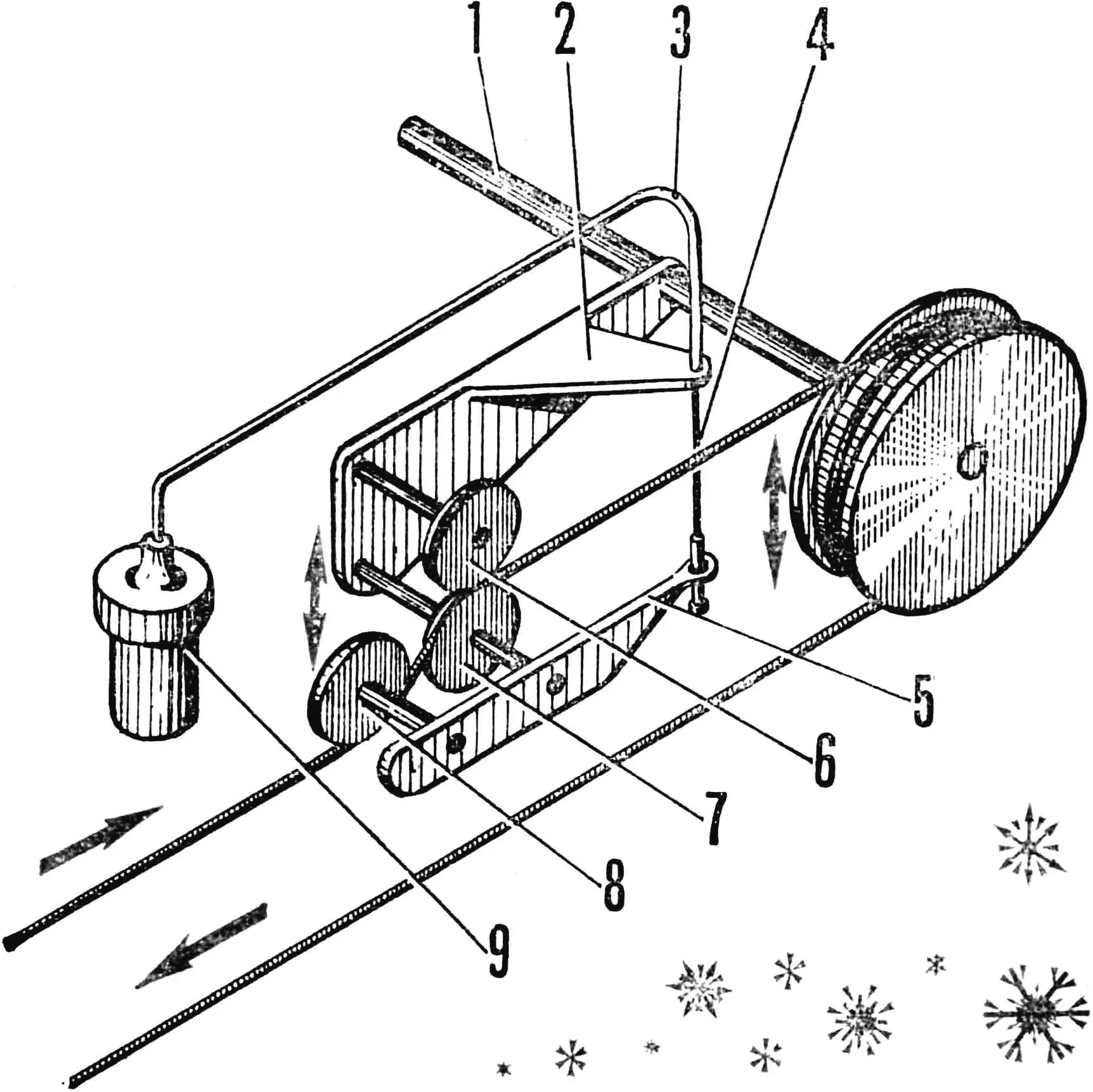
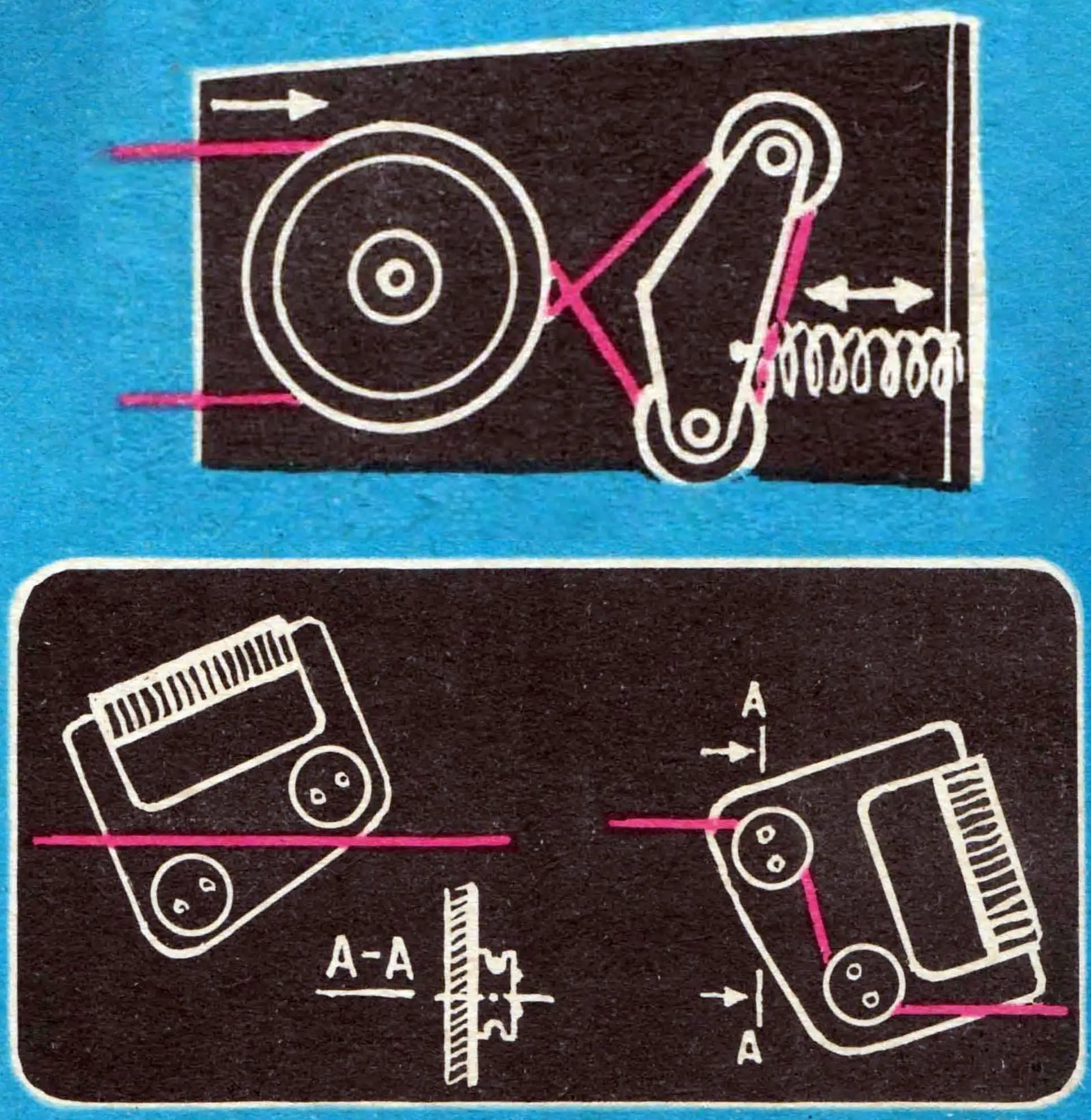
1 — drive shaft, 2 — throttle control drive mechanism base, 3 — slide cable sheath, 4 — carburetor slide cable, 5 — control lever, 6 — fixing roller, 7 — base roller, 8 — bending roller, 9 — carburetor slide chamber.
The design of the simplest throttle control (Fig. 2) is as follows: a base is attached to the drive pulley shaft, on which the drive mechanism rollers are located. On the base roller axis there is a lever, on one side carrying the bending roller, on the other — connected to the carburetor slide cable. The load created by the traction cable bending force at idle is balanced by the force of a specially selected carburetor spring. When the load increases (skier lift), the bending roller rises up, turns the lever and pulls the cable, raising the slide and automatically increasing the engine speed. Without load, it runs at minimum adjusted speed, which significantly saves fuel and, in addition, simplifies the skier’s cable grip with the ski tow.
The frame-sled is secured with a guy cable to a stake deeply driven into the ground, or to a nearby tree; thanks to this, the lift is held on the slope. The return block is secured in the same way. The cable is stretched between the drive pulley and the return block. Usually, a galvanized cable Ø 4—6 mm is used, and removable eccentric ski tows are attached to it. In the non-working position — when transporting the lift — the cable should be wound on the frame handles. When operating a portable lift, no supports are required to maintain the cable. However, it is necessary to carefully monitor that the cable branches do not get tangled, do not rub against stones, and do not cut deeply into the snow cover.
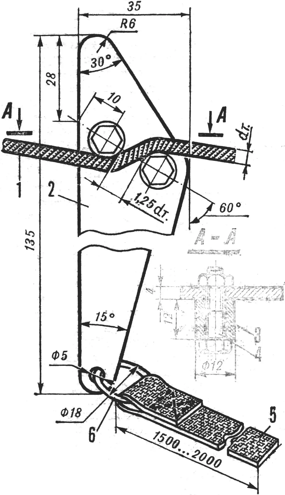
1 — traction cable, 2 — ski tow plate, D16T, 3 — bushing, brass, 4 — bolt M6X25, 5 — strap, 6 — strap ring.
The installation of an exhaust muffler to reduce noise levels is of great importance, which, of course, will make the rest more pleasant.
The design of various lift options has shown the possibility of actually ensuring its weight within 60 kg, including the working fuel supply — 10 l. The lift allows 10—15 skiers to climb simultaneously.
Now let’s consider the designs of ski tows — special devices with which the skier grips the cable and thus can climb up the slope. Ski tows can be permanently fixed on the moving cable or removable.
The simplest removable lever-type ski tows work on the principle of jamming or bending the moving cable (Fig. 3). They can also have an eccentric mechanism (Fig. 4). Lever-type ones consist of a metal triangular plate of somewhat elongated shape and a pair of bushings on bolts. The bushings are placed at a certain distance from each other, usually equal to 1.25 times the cable diameter, so that it can be reliably clamped between them. The plate corners are rounded, and a strap is attached to its long end on a ring.
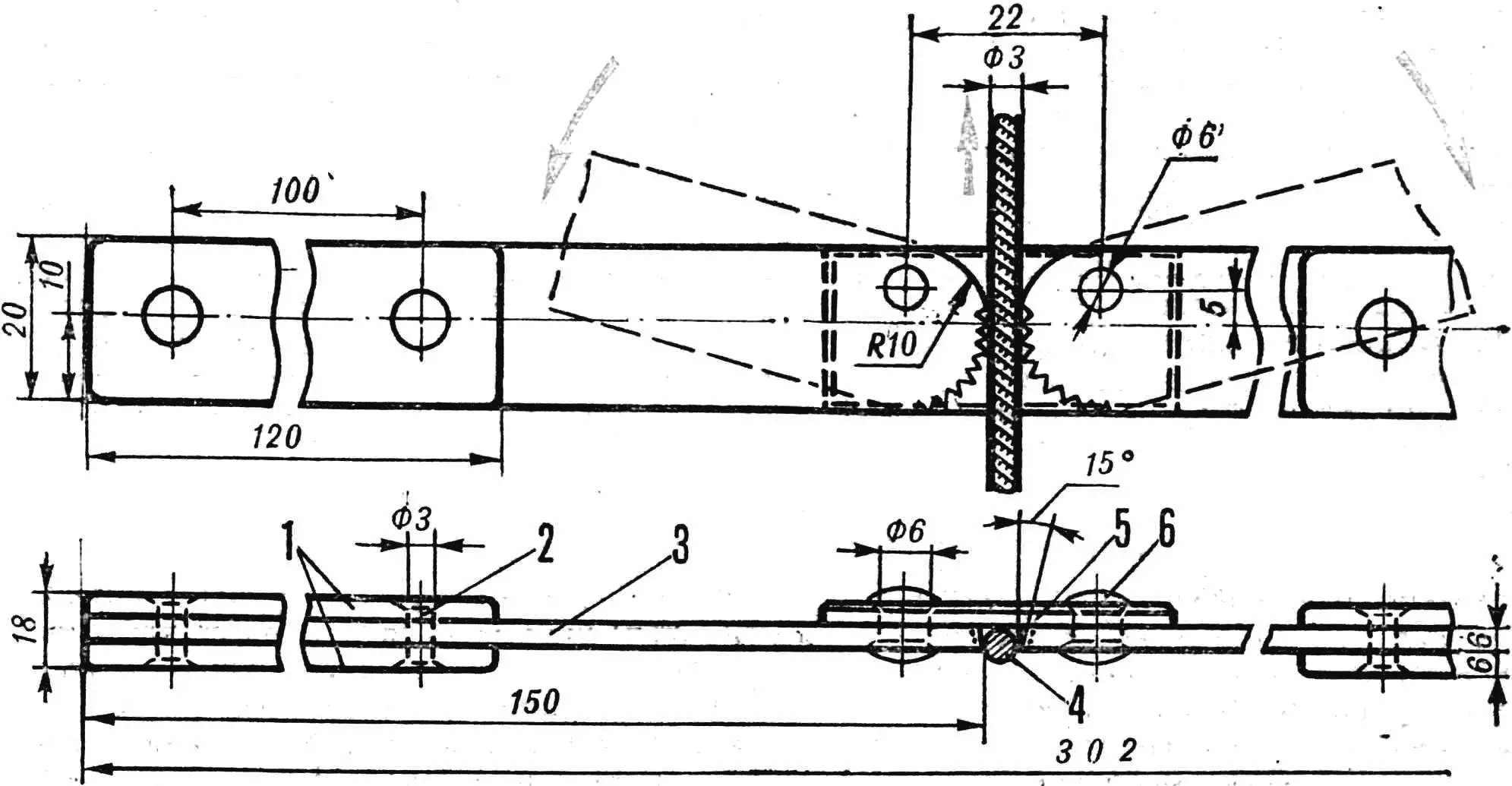
1 — pad, textolite, 4 pcs.; 2 — rivet Ø 3 mm, steel, 4 pcs.; 3 — handle, steel, 2 pcs., 4 — traction cable; 5 — shackle, steel, 6 — rivet Ø 6 mm, steel, 2 pcs.
The eccentric ski tow is of more complex construction, but it is more convenient and easier to grip the cable when “boarding” the lift. It consists of two metal handles with textolite pads and a metal shackle between them. The inner ends of the handles have shallow notches, are rounded and set relative to the shackle on eccentrics, the role of which is played by steel rivets. When making such a ski tow, it must be remembered that the distance between the clamp ends is chosen strictly depending on the cable diameter.
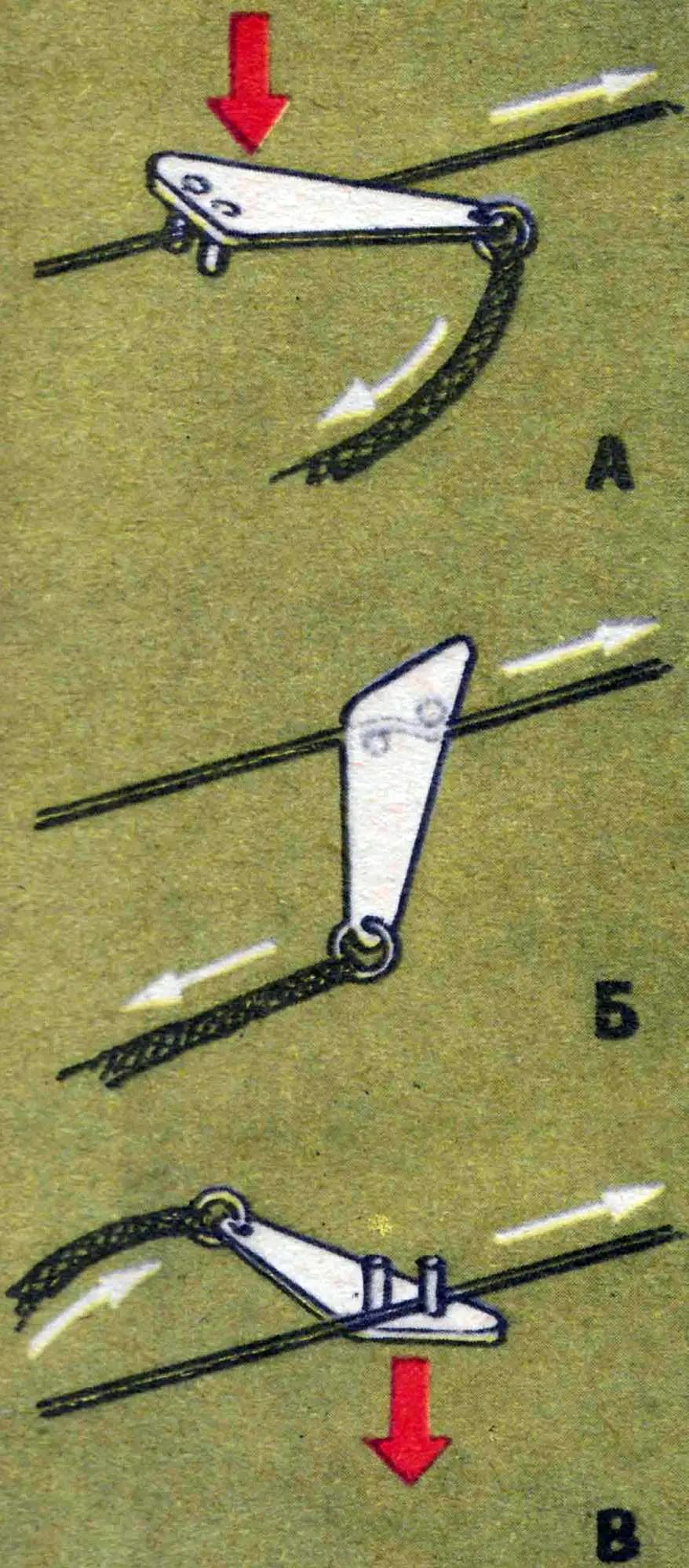
A — fixing the ski tow on the cable.
B — position when the skier climbs uphill.
C — removing the ski tow from the cable.
Before climbing the mountain with the help of a tow, learn to use ski tows. Remember that it is unacceptable to make a loop on the strap and put your hand through it or wrap the strap around your wrist, you also cannot grab the cable with your hands even in gloves or mittens; the “boarding” and “disembarking” areas of the lift must be equipped with horizontal platforms. Now take the ski tow in your hand, bushings down, put the strap in the other. Set the ski tow on the cable and slightly tighten the strap — the cable will slip for now, but if you pull it harder, the ski tow will jam the cable and go up with it. This moment is the most critical: if you loosen the tension, the ski tow may come off. To prevent this, manage to adjust the strap tension with your hand. Before starting to move up, take a step forward, this will soften the jerk, reduce the load on the engine, and it will be easier for you to board.
When approaching the return block of the lift, you need to release the cable from the ski tow. To do this, it is enough to slightly loosen the strap tension, first pulling yourself forward a little with your hands, and then quickly straightening them. You can also take an energetic step forward, pushing off with your ski so as to slightly overtake the moving cable: then the strap will sag and the ski tow will fall. Remember that you cannot throw the strap without releasing the ski tow from the grip — the cable may spring back, and then the strap will wrap around the cable. In the best case, it will be cut in the return block, in the worst case — an accident with the lift failure is possible.
EXAMPLE OF FUNICULAR CALCULATION
As an example, we will give a calculation of a towing lift for a single-cylinder two-stroke engine from the Tula cargo scooter TGA-200 “Ant”, which has a power of 12 hp at 5200 rpm, forced air cooling and a four-speed gearbox.
Required data for calculation:
- power — U=12 hp
- given speed of skier ascent on first gear — V=2 m/s
- lift efficiency — η=0.8
- track length — L=150 m
- elevation difference — H=55 m
- ascent angle — α=20°
- skier weight — G=70 kgf.
1. Determine the required force S for lifting one skier:
where F is the friction force, T is the tangential component from the skier’s weight.
where N is the normal component from the skier’s weight, f is the coefficient of friction of skis on snow (f=0.035).
Then
2. Engine traction force:
3. Possible number of skiers simultaneously lifted by the lift:
4. Minimum distance between transported skiers:
5. Ascent time:
6. Lift capacity:
where τ=3600 s.
«M-K» 2’82, Yu. ZOTOV, N. SHERSHAKOV
Recommend to read
 RAM INSTEAD OF ROM
Debugging any program of the microprocessor, it is necessary many times to write and erase information in the chips ROM КР573РФ5 (РФ5). However, the online those is very limited. In the...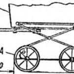 WITH STROLLER UP THE STAIRS
For families where a young child, is not without interest, perhaps, will be the proposed revision of the pram. Quite a simple upgrade allows one person to easily raise or lower at an...
