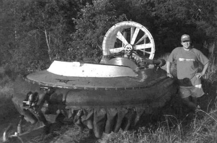
 We present a prototype of the amphibious machine is a device hovercraft (Ohr) under the name “Aerodzhip”, publication of which was in the journal “modelist-Konstruktor” No. 7 for 2007. Like the previous machine, the new machine – a single-engine, single-rotor with distributed air flow. This model is also triple, with the location of the pilot and passengers at the T-scheme: pilot middle front, and passengers – on the sides, back. Although there is nothing stopping the fourth passenger to sit behind the driver – seat length and power rotor setup is enough.
New car, in addition to improved technical characteristics, has a number of design features and even innovations that improve its reliability and survivability – after all, amphibious “bird” waterfowl. A “bird” they call her because over the water and over the land moves, it is still in the air.
Structurally, the new machine consists of four main parts: fiberglass body, bellows, flexible skirts (skirts) and propeller installation.
Taking the story on the new machine, will inevitably be repeated – because construction is largely similar.
Corps amphibious identical to the prototype size and design – fiberglass, double volume, consists of inner and outer shells. Here it is worth noting that the holes in the inner shell, the new unit is now not at the top edge of the sides, and about midway between it and the bottom edge, which provides more rapid and stable creation of an air cushion. Now the holes are not oblong, and round, with a diameter of 90 mm. there are about 40 pieces and they are located evenly at the sides and front.
Each shell was wycliffes in their matrix (used from previous designs) of two or three layers of fiberglass (and the bottom – of the four layers) on a polyester binder. Of course, these resins are inferior to vinyl-ester and epoxy for adhesion, filtration rate, shrinkage, and emission of hazardous substances when dry, but has an undeniable advantage in price – they are much cheaper, which is important. For those who intend to use such the resin, remember that the place of work, should have good ventilation and temperature not less than +22°C.

Fig. 1. Euroempire:
1 segment (set of 60 PCs); 2 – cylinder; 3 – mooring duck (3 pieces); 4 – wind hood; 5 – handrail (2); 6 – mesh enclosure of the propeller; 7 – outer part of the annular channel; 8 – the rudder (2); 9 – the lever handlebars; 10 – access hole in the tunnel to access the fuel tank and battery; 11 – pilot’s seat; 12 – passenger sofa; 13 – engine; 14 – the paddle (2 PCs.); 15 – the muffler; 16 – the filler (foam); 17 – the inner part of the annular channel; 18 – the lantern navigation light; 19 – propeller; 20 – bushing of the propeller; 21 – drive toothed belt; 22 is the attachment of the container to the shell; 23 – clamping of the segment to a casing; 24 – engine Motorama; 25 – the inner shell of the housing; 26 filler (foam); 27 – the outer shell of the housing; 28 – the dividing panel of the injected air flow
The matrix was made in advance by the master model of the same on the same made glass Mat, polyester resin, only the thickness of their walls was bigger and was 7 -8 mm (shells of body about 4 mm). Before vikaki elements with the working surface of the matrix was carefully removed all the roughness and burrs, and she was covered three times diluted in turpentine wax and polished. After that, the surface spray (or roller) was applied a thin layer (0.5 mm) and gelcoat (color coat) red.
After drying has begun the process of veclachi shell on the following technology. First, using a roller wax matrix surface and one side sakamato (with smaller pores) promazyvaetsya with resin, and then the Mat is placed on the matrix and rolled up until all the air is removed from under the layer (if necessary, you can make a small slot in the Mat). In the same way fit and subsequent layers made glass Mat to the desired thickness (3-4 mm), installation where needed, embedded parts (metal and wood). Excess flaps on the edges when you cut off the adhesive “wet”.

Fig. 2. Shell housing amphibians:
and the outer shell;
b – inner shell;
1 – ski(tree);
2 – under engine plate (wood)
After manufacturing separately the outer and inner shells they were docked, was held together by clamps and screws, and then glued along the perimeter strips coated with polyester resin of the glass Mat of a width of 40-50 mm, which was manufactured by ourselves shell. After joining the shells to the edge of the petal studs were attached on the perimeter of the vertical side strap of the 2-mm dural strip with a minimum width of 35 mm.
Additionally, pieces of resin-impregnated fiberglass, carefully glue all the corners and places of screwing fasteners. The outer shell is covered with gelcoat is polyester resin with an acrylic additives and wax add Shine and water resistance.
It should be noted that the same technology (for it was made the outer and inner membranes) wileyways and smaller elements: the inner and outer shell of the diffuser, wheels turn, engine cover, petroupoli, the tunnel and the driver’s seat. The gas tank (industrial from Italy) 12.5 l is inserted into the body, in the console, before bonding the lower and upper parts of the buildings.

The bottom of amphibians:
the inner shell of the housing with the air outlet holes to create an air cushion; above hole – number of cable clips for engagement of the ends of the scarf segment of the skirt; the bottom glued two wooden skis
Those who are just starting to work with fiberglass, I recommend to start making boats with these small elements. Total weight of GRP hull with skis and strip of aluminum alloy, the diffuser and the rudders from 80 to 95 kg.
 The space between the shells serves as a duct around the perimeter of the apparatus from the stern on both sides to the nose. The upper and lower part of this space filled with construction foam, which provides optimal cross-section air channels and additional buoyancy (and thus survivability) apparatus. Pieces of foam glued together with the same polyester resin material, and the shells were glued strips of fiberglass cloth is also impregnated with resin. Further, from air channels, the air exits through the evenly spaced holes with a diameter of 90 mm in outer shell rests on the segments of the skirt and creates a device under the airbag.
To the bottom of the outer shell housing for protection against damage from the outside longitudinal glued a pair of skis from wooden bruskov and aft of the cockpit (that is inside) – under-eye wood stove.
Cylinder. A new model of hovercraft has almost twice the displacement (350 – 370 kg) than the former. This was achieved through the installation of an inflatable balloon between the housing and the segments of the flexible skirts (skirt). The container is laminated of Mylar film on the basis of PVC material Upwap in Finland with a density of 750 g/m2 in the form of housing in the plan. It was tested on large industrial vessels, air cushion, such as “House”, “Pegasus”, “Mars”. For increasing the survivability of the tank may consist of several compartments (in this case three, each has its own filling valve). The compartments in turn are divided in half lengthwise and longitudinal partitions (but this version is still only in draft). With this design, the punched compartment (or even two) will allow you to continue on the route, and especially to get to shore for repair. For economical cutting of the material the cylinder is divided into four sections: the nose, two Barcarola. Each section, in turn, is glued of two parts (halves) shell: upper and lower – their patterns mirrored. In this embodiment of the container compartments and sections are not the same.

Fig. 3. Cylinder:
and the outer shell; b, the inner sheath;
1 – nose section; 2 – side section (2); 3 – feed section; 4 – divider (3 PCs); 5 – valve (3 PCs); 6 – litres; 7 – apron
On top of the cylinder glued “electros” – a strip of double-folded material Vinyplan 6545 “Arctic”, with an attached fold braided nylon cord, impregnated with glue “900И”. “Lectro” is applied to the side of the bar, and using plastic bolts cylinder is attached to an aluminum strip fixed on the case. Same runway (only without an attached cord) are glued to the cylinder bottom-front (“half past seven”), the so-called “apron” – which bind the upper part of the sections (tabs) flexible protection. Later to the front of the cylinder was glued a rubber bumper-the bumper.
 Soft elastic fence “Aerodzhip” (skirt) consists of separate but identical elements, segments, cut and sewn from dense lightweight fabric or film material. It is desirable that the fabric was waterproof, was not hardened in the cold and does not leak air.
I used again the material Vinyplan 4126, only smaller density (240 g/m2), but it’s perfect Patriotic fabric type percale.
The segments have a slightly smaller size than the “bottle” model. The pattern segment is simple, and stitch it myself even manually, or cook high-frequency currents (FA).
The segments snap the cover tab to likasu cylinder (two at one end, while the knots are inside under the skirt) around the perimeter “of Aeroamphibious”. Two lower corner segment, the nylon construction of the clamps freely suspended to a steel cable with a diameter of 2 – 2.5 mm long, clasping the lower part of the inner shell of the housing. Just the skirt is placed up to 60 segments. Steel wire 2.5 mm diameter is attached to the body by clips which in turn are attracted to the inner shell petal studs.


Fig. 4. Segment:
1 – handkerchief (the “Vinyplan 4126”); 2 tab (the “Vinyplan 4126”); 3 – lining (fabric “Arctic”)
Such fastening segments of the skirt is not much higher than the replacement time of the failed element is flexible fencing, compared to the previous design, when each is attached separately. But as shown, the skirt is operable even in case of failure of up to 10% of the segments and their frequent replacement is not required.

Fig.5 Shimmy of the cylinder and segments of the shells of the case:
1 is an outer shell casing; 2 – inner shell of the housing; 3 – panel (GRP) 4 — plank (made of anodized aluminum, strip 30/2); 5 – a screw-a screw; 6 – litres cylinder; 7 – plastic bolt; 8 – tank; 9 – the apron of the container; 10 – bucket; 11 – lacing; 12 clip; 13-clamp(plastic); 14-cable d2,5; 15-viagrasalela; 16-grommets
The rotor unit consists of engine, shestilopastnye propeller (fan) and transmission.
Engine – RMZ-500 (similar to “Rotax 503”) from a snowmobile “Taiga”. Produced by JSC “Russian mechanics” under the license of the Austrian company Rotax. Motor two-stroke, reed intake valve and forced air cooling. Established itself as a reliable, powerful enough (about 50 HP) and heavy (about 37 kg), and most importantly -a relatively inexpensive unit. Fuel – gasoline AI-92 mixed with oil for two-stroke engines (for example, domestic MHD-14M). Average fuel consumption – 9 – 10 l/h. the engine is Mounted aft of the apparatus, Motorama attached to the bottom of the case (or rather, to the under engine wooden stove). Motor mount was higher. This is done for convenience of cleaning the aft part of the cockpit from snow and ice, which enter through the side and accumulate there, and freeze when you stop.

Fig. 6. Transmission and the attachment points of the rotor position:
1 – output shaft of the engine; 2 – a leading gear pulley (32 tooth); 3 – belt gear; 4 – toothed driven pulley; 5 nut M20 mounting axis; 6 – spacer sleeves (3 pieces); 7 – bearing (2 PCs); 8 – axis; 9 – bushing screw; 10 – front strut bearing; 11 – front nadvorna bearing; 12 — front strut bearing-Dunga (not shown, see photo); 13 – the outer cheek; 14 – inner cheek
The propeller – shestilopastnye, fixed pitch, diameter 900 mm. (was trying to install two five-bladed coaxial rotor, but it was unsuccessful). Bushing screw, duralumin, cast. The blades of fiberglass coated with gelcoat. Axle bushing screw was lengthened, though it remained the same bearings 6304. Mounted on the axis of the rack above the engine and is locked there by two struts: two – and three-beam front – to-rear. Before you screw mesh grille fencing, and behind – the feathers are the air rudder.
The transfer of torque (rotation) from the engine output shaft on a bushing of the propeller is via a toothed belt with a gear ratio of 1:2,25 (drive pulley has 32 teeth and the driven – 72).
The airflow from the propeller divided by a partition in the annular channel into two unequal parts (about 1:3). A smaller part of it goes under the bottom of the housing for creating an air cushion, and large – on the formation of propulsive forces (thrust) to move. A few words about the peculiarities of driving amphibians, specifically the beginning of the movement. When the engine is idling, the apparatus remains stationary. With increasing speed, amphibious at first raised above the supporting surface, and then starts moving forward if the rpm is from 3200 to 3500 per minute. At this point it is important, especially when starting from the ground to the pilot initially lifted the rear part of the device: then the aft segments will never engage, and the front praskolesy over bumps and obstacles.


Fig. 7. Sub frame:
1 – the base (steel sheet s6, 2); 2 – gantry stand (steel sheet s4,2); 3 – jumper wire (steel sheet s10, 2 PCs.)
Management “Aerodzhip” (change of direction) is the aerodynamic rudders pivotally mounted in an annular channel. The deflection is performed by duplicera lever (handlebar motorcycle type) through the Italian Bowden cable going to one of the surfaces of the aerodynamic rudder. The other plane is connected to the first rigid rod. On the left arm lever fixed lever to adjust throttle control the carburetor or “the trigger” from a snowmobile “Taiga”.

Fig. 8. Steering control scheme:
1 – wheel; 2 – the Bowden cable; 3 – node of attachment of the braid to the body (2); 4 – budenovskaya braid rope; 5 – bar steering; 6 – an arm; 7 – thrust (rocking conventionally not shown); 8 – bearing (4 PCs.)
Braking is by “throttling”. When it disappears airbag and the apparatus body rests on the water (or skiing – on snow or the ground) and stops due to friction.
Electrical equipment and devices. The machine is equipped with a rechargeable battery, tachometer with hourmeter, voltmeter, temperature indicator engine head, halogen headlights, push button and the key off the ignition on the steering wheel. the engine starts with the electric starter. Possible to install any other devices.
Amphibious boat called “Fisherman 360”. He completed sea trials on the Volga: in 2010, the meeting of the company “Welched” in the village of Emmaus near Tver, Nizhny Novgorod. Participated at the request of the Department in performance at the celebration of the Navy day in Moscow on the Rowing channel.
Technical data “Aeroamphibious”:
Overall dimensions, mm:
length……………………………………………………………………..3950
width…………………………………………………………………..2400
height…………………………………………………………………….1380
Engine power, HP……………………………………………….52
Weight, kg…………………………………………………………………….150
Load capacity, kg………………………………………………….370
Fuel capacity, l…………………………………………………………….12
Fuel consumption, l/h………………………………………………..9 — 10
Overcoming obstacles:
ascent, hail……………………………………………………………….20
wave, m……………………………………………………………………0,5
Cruising speed km/h:
on the water……………………………………………………………………….50
on the ground……………………………………………………………………54
on the ice……………………………………………………………………….60
M. YAGUBOV Honorary inventor of Moscow


