While still a student at the Faculty of Industrial and Civil Engineering, my father quite often fantasized about technology, transport and various self-propelled mechanisms. I remember, when I was still very young, I opened his notebooks with interest and looked at the diagrams he drew, asking questions. In the 1990s, Dad’s hobby was further developed and turned into a patent for the invention of the “All-wheel drive vehicle chassis.” By that time, my interest in cars, especially off-road vehicles, had developed. And I began to persuade my father: “Let’s build what you came up with.” But the time was completely inopportune, the papers remained papers, and the idea was shelved…
However, after some time, my father nevertheless made an attempt to translate his drawings into metal. The project was called “Scam”. But in terms of the degree of development and technical characteristics, it turned out to be raw, so it was sent to the far corner of the yard.
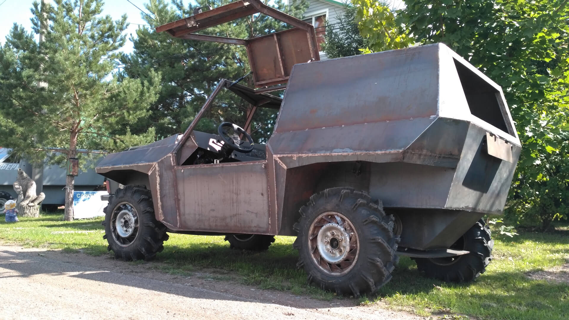
And a couple of years ago, my father announced: “I think now we can do everything right. But only if you are with me! I can’t handle it alone.” So the decision was made to build an amphibian. The car was called “Shah”. While my father was cutting and welding the metal that was to form the basis of the car, I took up a pencil and tried to imagine how I wanted the future body to look.
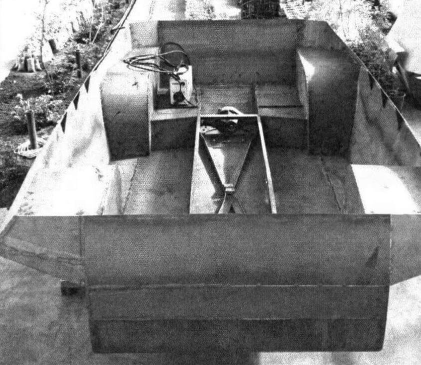
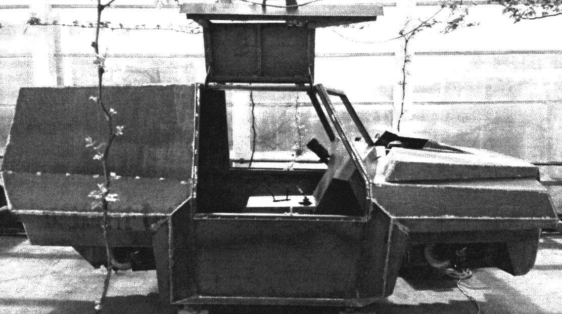
In the spring of 2019, we welded the base of the body in one month. The bottom is made of 3 mm steel, and everything above is made of 2 mm thick steel. Essentially, it is a load-bearing structure without a frame or subframes. The inner parts of the arches are the only bent elements, the rest of the body is welded from straight plates.
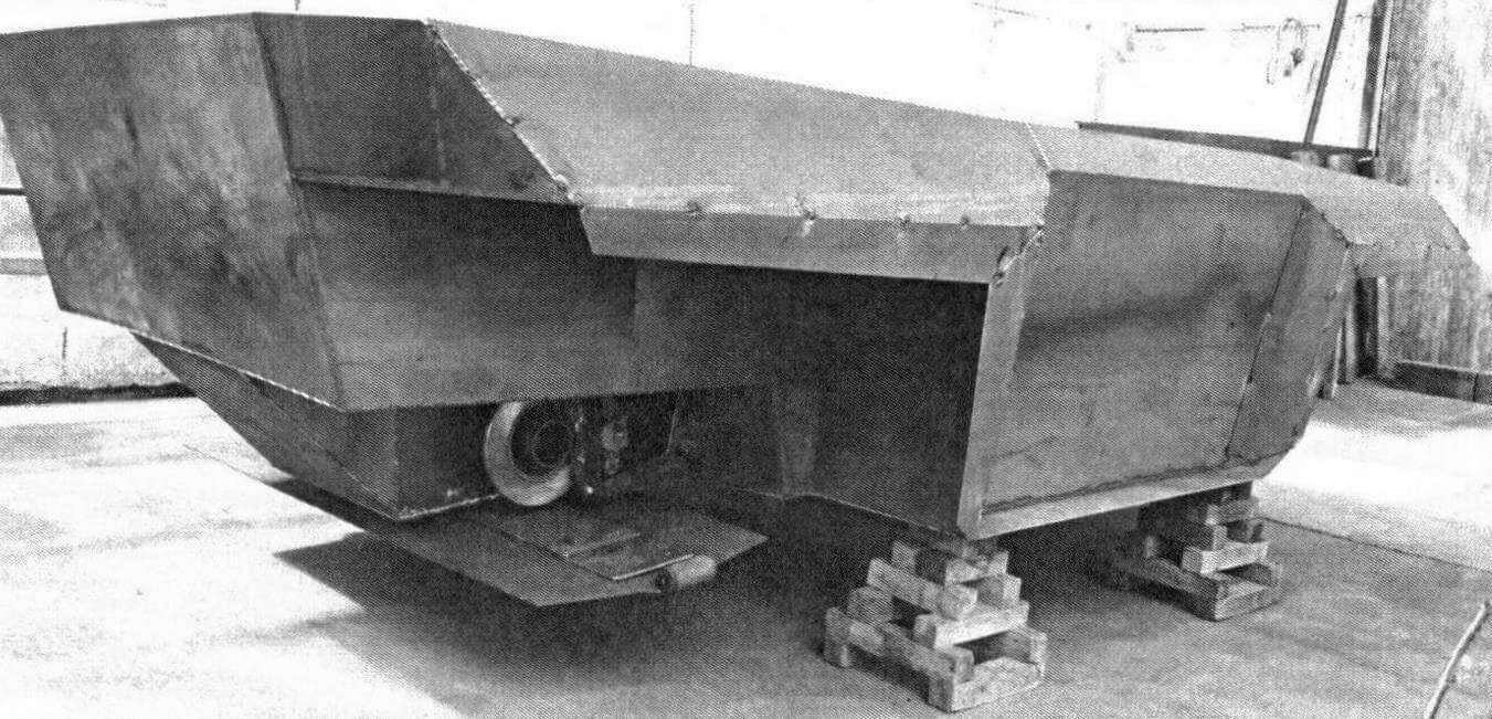
The next stage was work on the body above the sill line. From the very beginning we knew that the doors would be gullwing doors. For what reasons, you ask? Firstly, we have an amphibious vehicle, which means that such doors can be opened when moving on water. Secondly, they require less room to open in tight spaces and do not interfere with walking around the car. And thirdly, which is also important, they are damn beautiful! It is no coincidence that such a scheme is used on some supercars.
Then it was the turn of the engine compartment hood. What is the best way to do it: so that it leans forward (against the direction of movement) or backwards (along the direction of movement)? We chose the first option. The main arguments: such a hood will not open spontaneously when suddenly driving into the water; there is convenient access to the engine afloat – open the door and step onto the wing; In this case, the tilt angle of the hood is greater,
After all, our central front pillar protrudes forward.
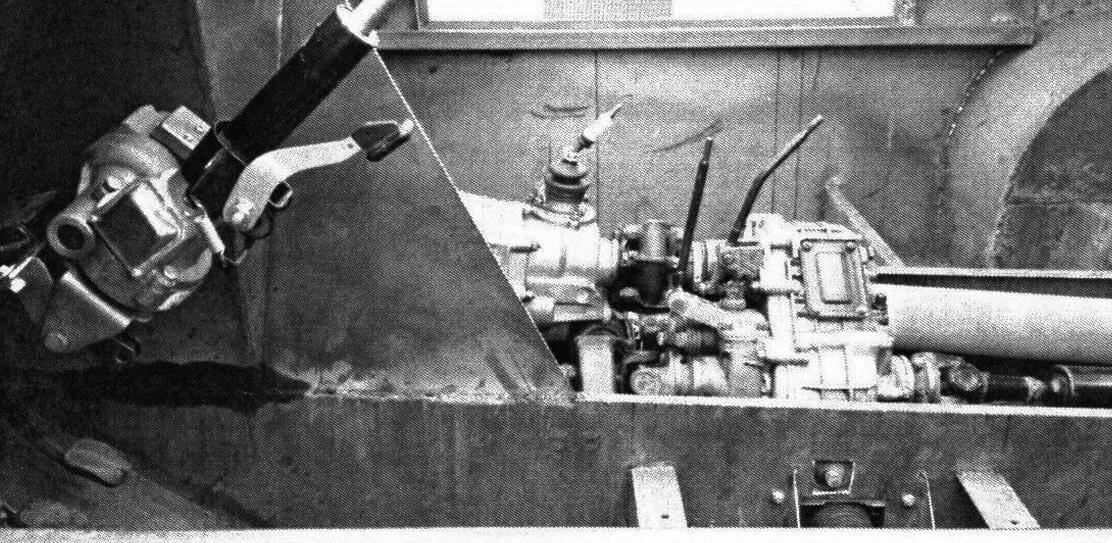
The donor for “Shah” was his father’s previous car, a VAZ-21213 produced in 2000. The engine with all attachments, gearbox, transfer case and driveshafts were all removed, cleaned and serviced. The bridge stockings, cut and turned upside down, were installed during the floor welding stage. The wheelbase remained the same, so the wheelbase and cardans fit without any problems, you just had to weld on the brackets. At the same time, it was decided to swap the rear and front driveshafts, which made it possible to move the gearbox, gearbox and engine 250 mm back. This improves weight distribution along the axles, and the transmission control levers can be placed closer to the driver. But there is also a disadvantage of this arrangement – the engine shield extends into the cabin.
The oil filler neck on the valve cover is welded to the opposite edge. The engine mounts remain “original”, and the mounting brackets are homemade. The gearbox crosspiece is cut to size, with a different location of the mounting holes. The brake master cylinder and clutch master cylinder are mounted on the left side of the engine shield. A modified exhaust system is installed in the central tunnel. The entire exhaust tract is made on clamps. The exhaust is routed to the rear side under the glazing line. The engine compartment is designed with a length reserve so that a winch can be installed later.
Steering. We’ve seen many designs for fully steerable chassis, but in them the rear wheels turn in a similar way to the front wheels in a regular car. In the end, I’ll figure it out
or its own completely original design of rotation with swinging axle shafts. What does this give? When turning, the tracks of the rear and front wheels coincide, that is, on off-road the car uses its rear wheels to follow the tracks of the front wheels and chews through two tracks instead of four. Another trump card is that while driving, you can change the length of the wheelbase, approach and departure angles along the sides. We have a slightly modified steering rack from a VAZ-2108, which, through a rod system, activates the turntables under each of the axles. The mechanism is located under the driver’s seat. Initially, it was planned to transmit rotation from the steering shaft to the rack through a flexible shaft, but later this idea was abandoned in favor of the usual cardans – it’s more reliable.
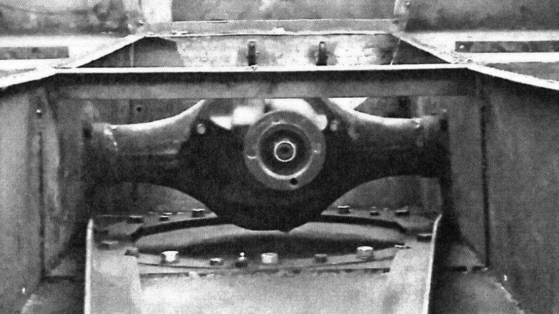
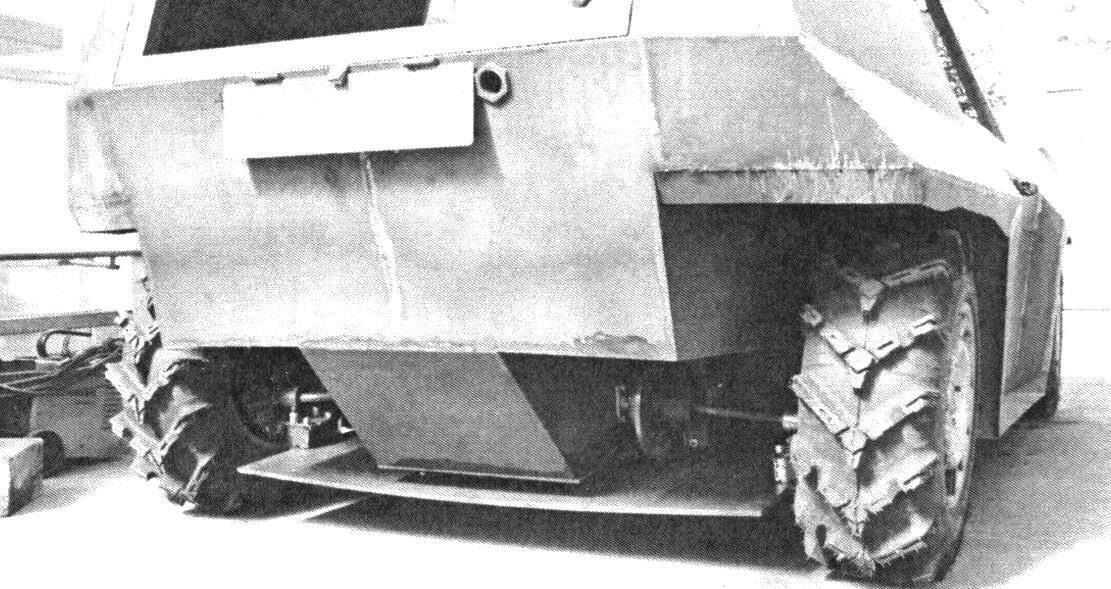
The chassis is based on round rotating platforms, movably mounted on thick-walled metal platforms at the front and rear. This is vaguely reminiscent of the platforms at the base of crane and excavator cabins. Rods made of a metal profile are connected to the platforms in an A-shape, which, in turn, are connected by another round rod with silent blocks. The design is driven by a steering rack. Electric power steering column from a Lada Kalina car.
The fuel tank is installed under the passenger seat. We didn’t bother looking for ready-made products; we ordered them in size from Ufa craftsmen. The tank with a capacity of 50 liters with a honeycomb structure is made of aluminum sheet, the equipment is from Niva. The filler neck is located in the cabin behind the passenger seat.
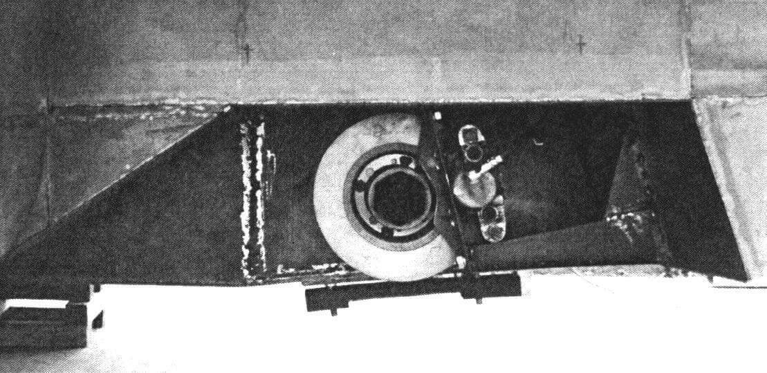
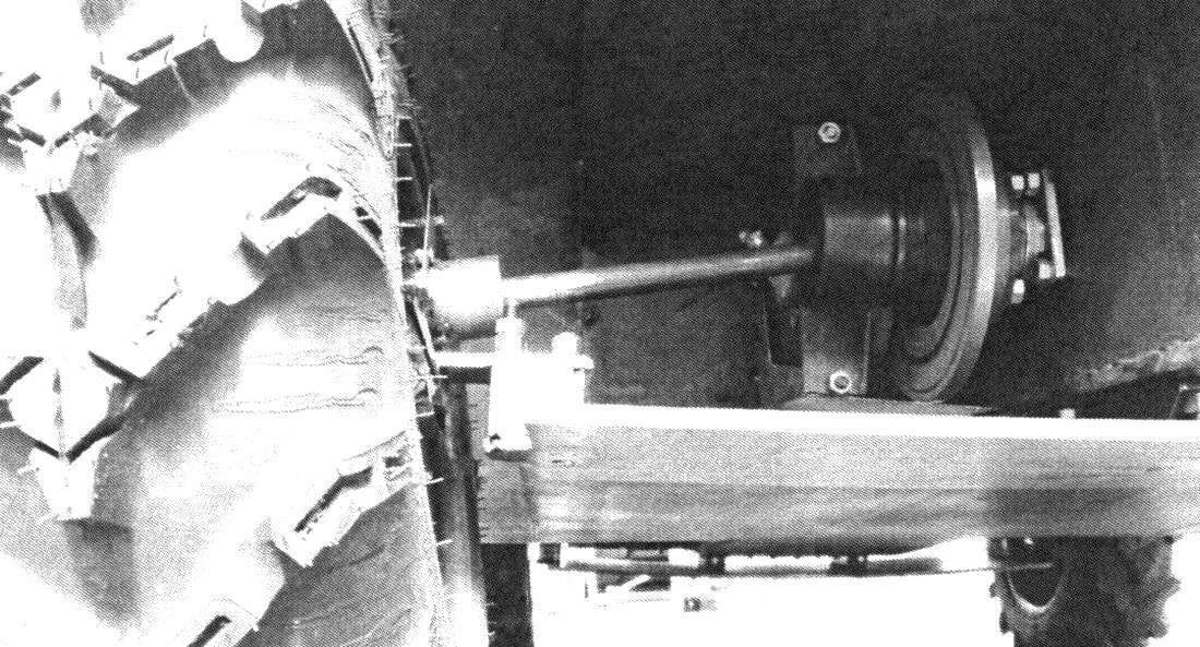
The brake system is made according to the original design. The brake mechanisms are not mounted on the hubs and are not located inside the wheel rims, but are located near the central tunnel, that is, at a distance from the vehicle track. This scheme is not new; it can be seen, for example, on the Hummer H1 and on some other types of military equipment. In our case, these are brake discs and calipers from a VAZ-2108 installed in a circle. The brake disc sits on a long “grenade” (from the Niva), which goes into the cut stocking. The brake caliper is mounted on a homemade bracket, the brake hose goes into the central tunnel along the shortest path. This design is easy to implement, provides good protection for the brake pipes, although slightly, it reduces the unsprung mass and leaves room for wheel gears. Yes, replacing brake discs will be more difficult, but let’s be realistic – most likely, they are here for the entire life of the car, just like the pads. The pedal, vacuum booster, and master brake cylinder are standard Niv ones. The brake lines from the cylinder to the hoses were purchased from a local auto shop. Back from the engine compartment, the line runs through the central tunnel on the side opposite the exhaust system.
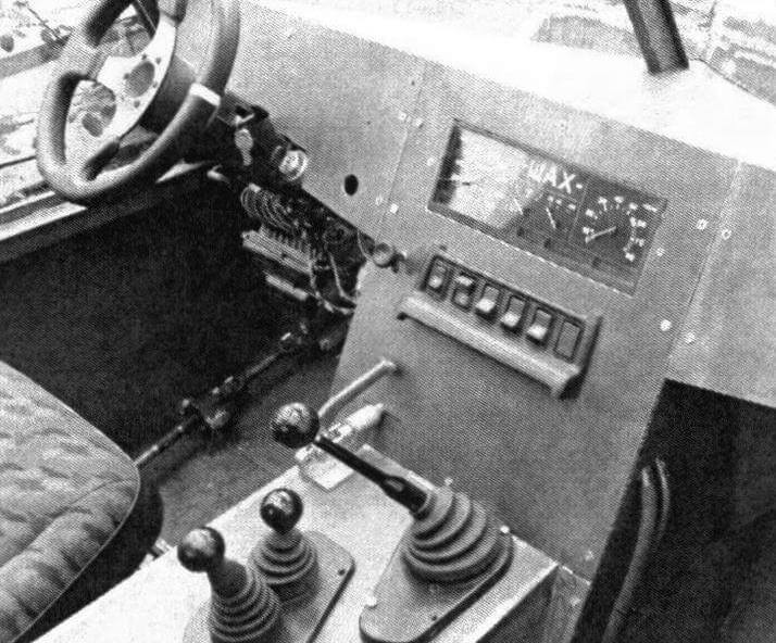
There were no surprises regarding electrical equipment. All wiring, relays, sensors and fuse box moved here from the VAZ-21213. We mounted the blocks on the plate to which the steering column bracket is attached. The battery is installed under the hood, near the front right pillar. Near it (opposite) on the passenger side of the engine shield there is a switch. The wiring leading to the electrical equipment in the rear of the body is laid in the main amplifier, running along the side on the driver’s side.
The first launch of the engine took place in April 2020, exactly one year after the start of active work on the project. Fifteen minutes of idling and in different gears showed that the oil pressure with the new configuration of the oil receiver-pan is normal – the lamp goes out quickly after starting. The temperature did not rise above 90 degrees.
As you know, the most important part in a car is the steering wheel! Searches around the city did not yield anything, I had to order: minimalism, no flight, “leatherette” – just what I needed! The insert of the instrument cluster and all the keys is in the center, let the navigator also keep an eye on them.
The key element of the entire design was the transverse wide springs-skis in the front and rear of the car. Both front and rear springs have certain angles of attack. Together with the shape of the arches and the flat bottom, this gives its effect when moving through the water. Only the third time we managed to correctly select the thickness of the 65G spring steel sheet and achieve adequate ground clearance and elasticity.
The spring before last I bought a set of wheel gearboxes from LuAZ. The drive shaft with the cross was immediately removed as unnecessary. Their place was taken by a modified classic axle shaft. Then a flange with a pipe is attached to the gearbox housing in the standard holes, a bearing is installed on the shaft and secured in the pipe with a retaining ring. Next, a thick-walled ring with an improvised earring is attached to the pipe, which is “tied” to the spring through a spacer. At the end, a cage with a separator is installed and locked on the axle shaft. The ground clearance on our car is adjustable. To do this, you need to unscrew a single bolt, and the gearbox housing (and hence the wheel) rotates 180 degrees around the axis of rotation. The machine has two fixed clearance positions: approximately 150 and 300 mm, that is, for water and land, respectively.
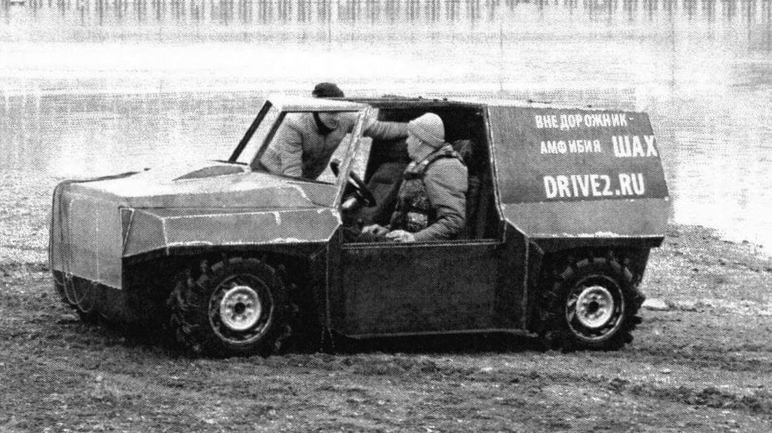
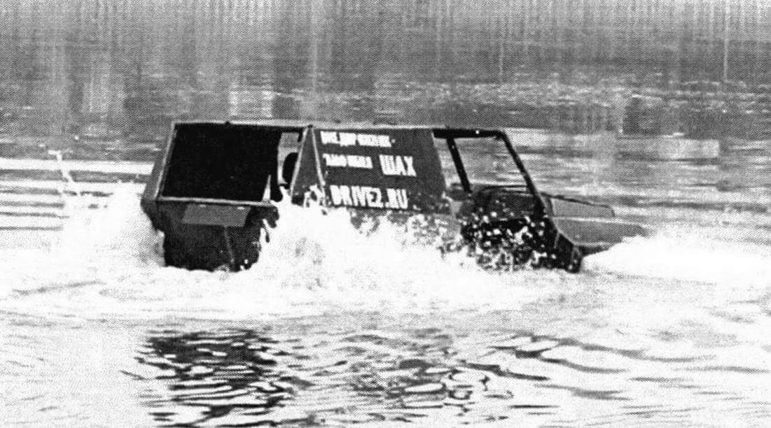
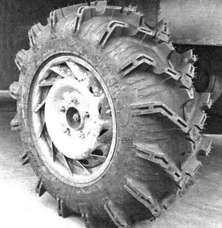
When the idea of creating this car was just emerging, the question of choosing tires immediately arose. Yes, on the water we will move using the wheels. But which ones? The water needs to be scooped up with something and thrown away. Remember what steamships with paddle wheels look like. For an amphibious vehicle of our class, a compromise is needed between an ordinary civilian tire and these steamship blades. Huge Sherpa lugs immediately come to mind, but we don’t use low-pressure tires, and we haven’t seen small tires with similar “oars.” What else can cling to water? Tractor herringbone. We started monitoring agricultural machinery, and it became clear that in terms of speed indicators nothing suited us. Even if you manage to find a tire with the required geometry, there is a fear that it will fly apart at high speed. Taking into account our power supply, we estimated the maximum diameter of “toothy” tires that the Niva transmission and LuAZ wheel gearboxes can handle. We agreed that we are not considering anything larger than 700 mm. They built the body under these conventional 27 inches, looked in the direction of ATV tires, and rolled ordinary crossover wheels into the arches for fitting. When the time came, ITP Cryptid 27×10-14 was found. The tire is tubeless, but since it is mounted “unwelded”, a tube was still installed. The assembled wheel pulled 31 kg, the final outer diameter was 660 mm.
Despite the harsh appearance, I wanted to make the car user-friendly and as comfortable as possible. Even at the stage of drawing sketches, images of the salon in which I would like to travel appeared in my head. The dreamer in me did not deny himself anything, but a rational person with a realistic view of things reassured me: “Don’t get excited! Everything you come up with must be implemented with the help of just two people and with the help of the means that they have.” It’s a paradox, but uncompromising technology is sometimes built solely on compromises!
This is how, gradually and step by step, our project, begun a year and a half ago, is taking shape. We know what kind of car we want to get out of it. And, frankly, we don’t know what we will get in the end. But we are trying! By the time this material was prepared (last fall), several test trips and one swim had been carried out. Initial tests have shown that some solutions do not work. The car was disassembled, the components were redone. Some elements in the suspension were changed as many as four times. After all, an amateur designer does not have the opportunity to come to the store and buy everything he needs, since the necessary parts simply do not exist. A lot of the steering system and almost everything about the suspension had to be made independently, and anything that required high precision had to be ordered from professional turners and millers. The workshop already has a small warehouse of elements that “didn’t go and didn’t go.” Through a series of trials and errors, we pave the way to the result we are waiting for, to the car we have in mind. But no matter what stage we are at, the concept of the project is laconic: everything you need is simple, everything complex is not necessary!
Arthur BAGAUTDINOV (Ufa, Bashkortostan)
