 Folk wisdom says that man’s life is not lived in vain, if you planted a tree, raised a son and built a house. And if the first two cases of special mechanisms is not required, when building a house can do without them. And the most necessary woodworking machineries — circular saw, power planer, milling machine, fixture for turning or instead of them — one multifunctional machine. It does not matter what the walls of the house: brick, concrete, or any other. No wood structures and materials is still not enough, since the tree — building material is not only versatile, but indispensable, especially for indoor decoration.
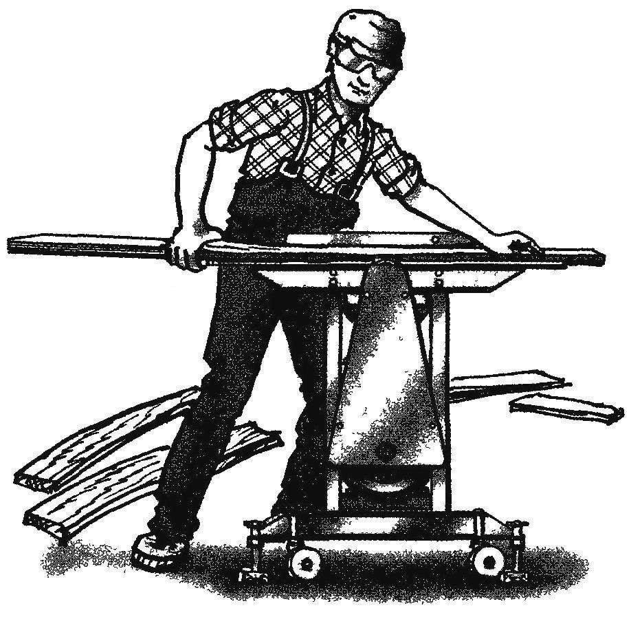
For those developers who intend to build a house but do not have “extra” money on supporting mechanisms, it is recommended to make a woodcutting machine, which can perform a number of operations: transversal and longitudinal (dissolution) cutting, planing and jointing, turning and milling, drilling and grinding, production spikes, and selection of slots. Well, with such versatility the machine can be useful and those for whom woodworking is a craft.
The design of the present cutting machine in all its listed features actually classic and fairly simple
Most parts and components are available for fabrication with his own hands in a home workshop. However, some nodes, such as cutting head, it is better to order specialists.
Welded joints a bit, but some of them can be replaced with riveting or threaded connections.
The material of the power parts (beams, pillars, girders) — mainly bright bars, rolled steel. It is a bit heavier machine, but greatly simplifies its manufacture
Before to start talking about the design of the machine, — one advice.
In the manufacture of area frames, a square and so n. preferably after marking the areas bend, close to bend the shelf to drill technological hole. first a thin drill (diameter 4 — 5 mm) and then drill a bigger (diameter 8 to 10 mm). Then you can cut the shelf “wedge” (isosceles right triangle) and bend the workpiece, the Operation in this case is easy and ensures high accuracy of manufacturing
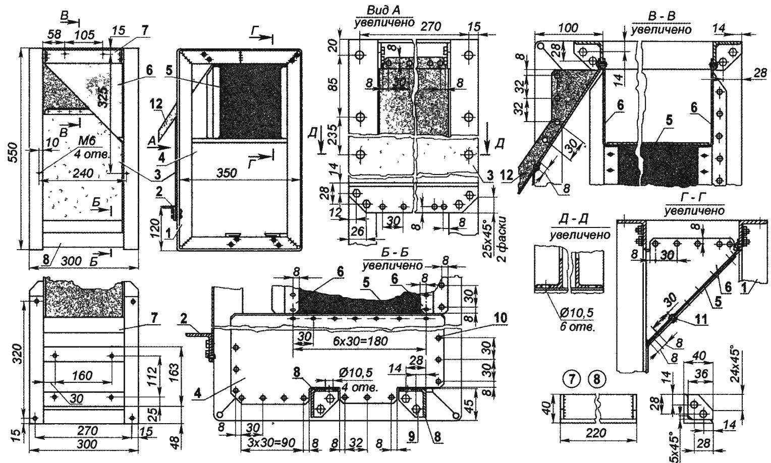
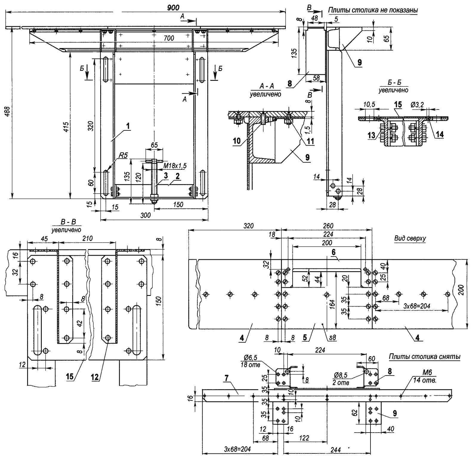
Machine frame:
1 — frame (2); 2 — thrust; 3 — the bottom side wall; 4 — the bottom front wall; 5 — upper front wall; 6 — upper side panel, 7 — bolt (2 pieces); 8 — motor support (2 PCs), 9— bolt M6 spring washer (20 PCs); 10 — steel blind rivet Ø3 (110 PCs); 11 aluminum rivet Ø3 (50); 12 — tray; items 1,2,7,8 made of steel area No. 4; details 3,4,5,6,12 made of duralumin sheet s1,5
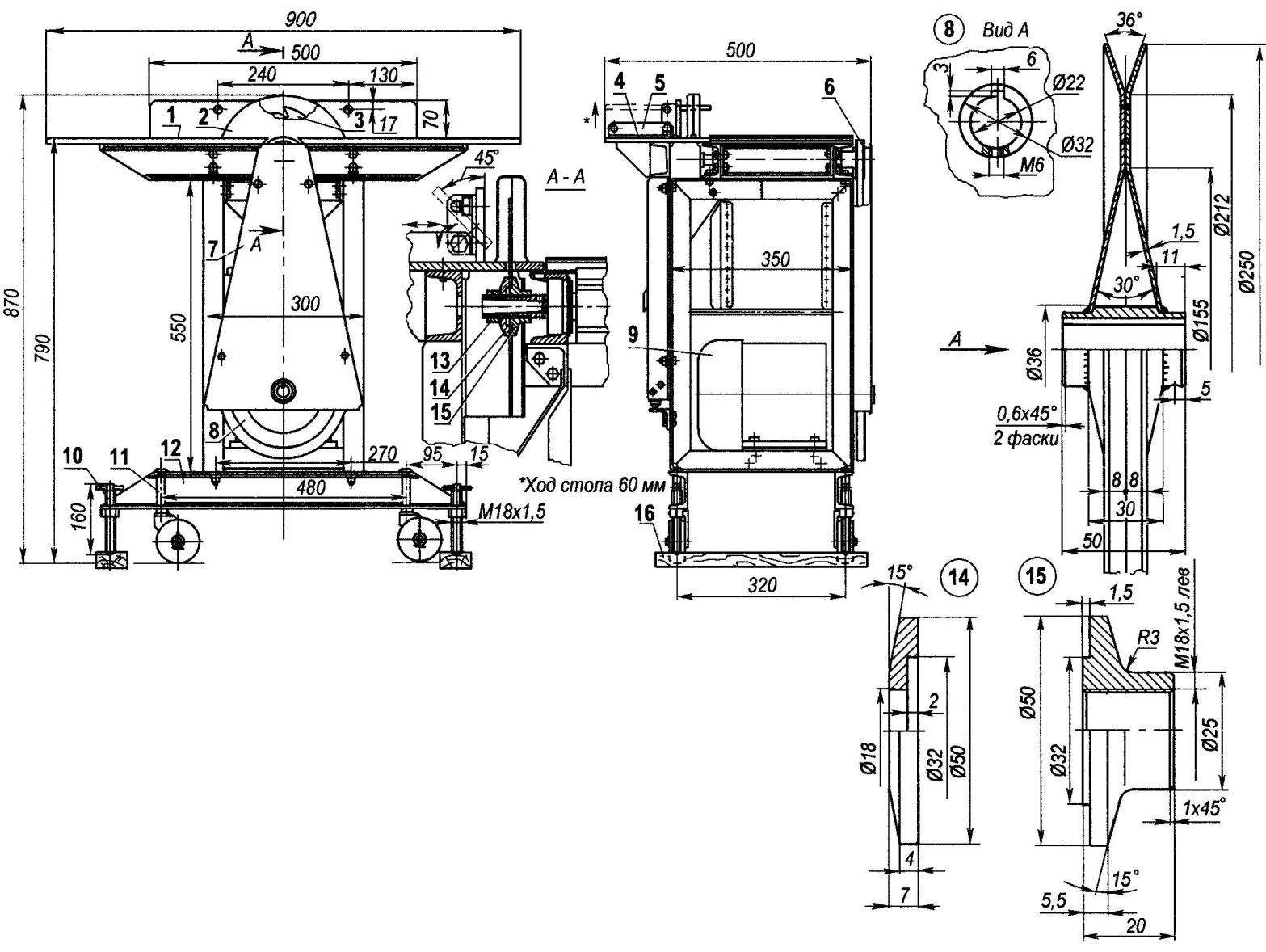
Diversified woodworking machine:
1 — work table with cutting head; 2 — a casing of circular saws (steel 5, the sheet s1,5); 3 — circular saw (purchased the product); 4 — lifting table; 5 — guide (Д16АТ, the sheet s8) with stops (area No. 4, 2); 6 — timing belt (purchased the product); 7 — drive casing (steel 5, the sheet s1,5); 8 — compound drive pulley (St3 flanges, sheet s1,5, 2 PCs, wheel hub — steel 25, range 36); 9 — electric motor (N = 1.5 kW, n = 1480 rpm); 10 — domcratic (4 PCs); 11 — wheel stand (4 pieces); 12 — lower beam-spar (channel № 6,5, 2); 13 — nut M18 x 1 5, left; 14 — special washer (steel 20, circle 50); 15 — unina special nut M 18×1,5, left (steel 20, circle 50), 16 — lining (wood, metal, 2 PCs)
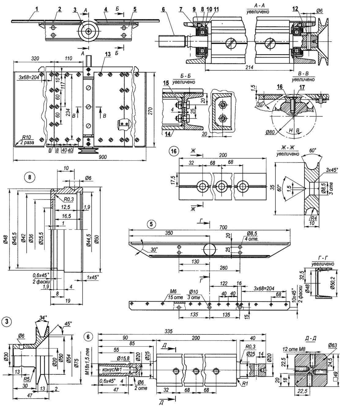
Work table with cutting head:
1 — extreme (large) plate (Д16АТ, the sheet s8, 2 PCs.), 2 — median (small) plate (Д16АТ, the sheet s8, 2); 3 — driven pulley (D16, circle 75), 4 — lining (St3, sheet s1,5, 3 PCs); 5 — podstolny beam-side-bar (channel № 6,5, 2-piece), 6 — shaft drum cutting head, 7 — the bearing retaining ring (2 PCs.) 8 — bearing (2-piece), 9 — stonery screw M6 (2 pieces), 10 — bearing 80104 (2 PCs); 11 — the lock ring of the bearing (2 PCs); 12 — pin (steel 25, lap 6); 13 — M6 screws (32 PCs), 14 — podstolny crossmember (Assembly unit channel No. 6.5, the sheet s4, 2 PCs.), 15 — bolt M8 spring washer (8 PCs); 16 — knife (steel 50KHFA, sheet .s10, 4 PCs); 17 — screw M8 (12 PCs)
The frame of the machine consists in turn of two part, connected at the bottom of the supports under the engine and above the crossbars. All these elements — from the corner No. 4 of the Frame rests on steel I-beams-rails of the base and at the top of her on the beams-is fixed cargo Desk. Beams made of channel number of 6.5. At the ends of the base beams mounted wheels, thanks to which the machine is quite heavy (weighing about 100 kg) able to move within a room or from one thing to another, adjacent room even for one person To operate mechanism is installed on wooden or metal linings using screw domkratov mounted on the ends of beams close to the wheels. At the bottom of the frame on the frame, providing the tension of belts is mounted an electric motor with a capacity of 1.5 kW (but can be more) and a rotation speed of 1450 rpm (motor with less rpm to install is not desirable). For start-up and motor operation the circuit includes a capacitor box, which is mounted in the upper part of the frame
Wall of the frame partially closed dural 1,5 mm sheet, and the inside is mounted an inclined tray on which chips and sawdust from under the cutting head removed installed next to the container or bag the Leaves are riveted to the frame.
The main part of the machine — work Desk with cutting head
Desk is made of duralumin sheet thickness of 8 mm and consists of four plates, two small (middle) and two large (extreme). Plate in pairs — mirrored. All the holes in them for the mounting screws with countersunk head is the same, and their arrangement in pairs of plates are also mirrored. Counter edge of the median plates facing the cutter head, is made with a bevel 30° inside. Under the back plate (median and extreme) planted strips of 1.5 mm thick, equal to the depth of cut when planing workpieces.
The cutting head is the main mechanism of the machine, which depends on the quality of workpieces By construction, it is not so difficult, but the quality of its workmanship should be high. With a lack of experience and if possible it is better (and along with the tailstock centre) to order the professionals who have good metal-cutting equipment.
The most important detail of the head, quite large and massive drum-shaft with cantilever ends in rolling bearings 80104. Directly on the drum are mounted four knife. The number of knives, rotational speed of the drum and the length of the working table on quality of treatment provide not planing, and jointing of the workpieces. All knives are the same — each has four cutting edges (blades). Structurally, the securing of the blades on the drum is arranged so that when dulled one blade knife adjustable: rotates or flips. Knife sharpening is done rarely — only when dulled all edges. If necessary, on the drum instead of knives can be mounted in a special mandrel sandpaper or felt and make the machine surface grinding, or polishing operation.
Lifting table:
1 — front (area No. 4, 2-piece — mirrored); 2 — crossmember (Assembly unit, area No. 4; St3, sheet s4 — 2 PCs, threaded bushing М18х 1,5), 3 — Jack (screw M 18×1,5); 4 — extreme Board (Д16АТ, the sheet s8, 2 PCs — mirrored); 5 — medium large plate (Д16АТ, the sheet s8), 6 — middle small plate (Д16АТ, the sheet s8), 7 beams (channel № 6,5), 8 — front bracket (St3, sheet s1,5, 2 PCs — mirrored), 9 — rear bracket (St3, sheet s1,5,2 PCs — mirrored), 10 — M6 screws with countersunk head (27 pieces); 11 — bolt M6 flat head screws and spring washer (16 set).; 12 — rivet with round head (St3, Ø3, on demand), 13 — bolt M8 spring washer (8 PCs); 14 — rivet with countersunk head (St3, Ø3, 8 PCs); 15 — pad (St3, sheet s1,5)
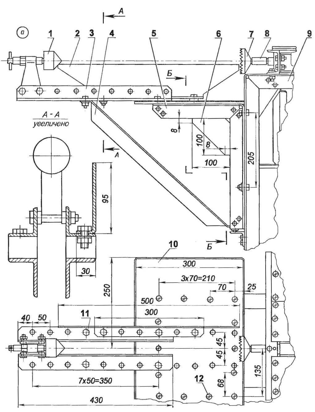
The prefix (and is in a lowered position with the oversight of consoles, b in a raised position without consoles):
1 — tailstock with center, 2 stand (St3, sheet s4), 3 — the console (area 40×40, 2 pieces); 4 — strut (40×40 area, 2 piece), 5 — the lifting bracket (40×40 area, 2 piece), 6 — Klondike solitaire (sheet s3. 2); 7 — carrier (steel 30KHGSA, circle 70) or tool (drill, mill, etc.); 8 — shaft-drum; 9 — frame of the machine, 10—lift table (Д16АТ, the sheet s8), 11 — bolt M6 spring washer (20 PCs); 12 — M6 screws with countersunk head (14pcs.), 13 — домкратикМ16х1,5; 14—traverse 15 — crossmember (Assembly unit, area No. 4; St3, the sheet s4, 2 PCs.)
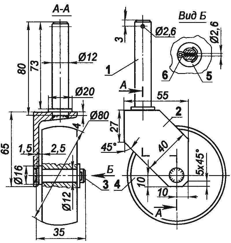
Wheel strut:
1 — front (steel 25, circle Ø20), 2 — bracket (channel № 6,5); 3 — axis (steel 25, circle Ø16), 4 — wheel (D16T, round Ø80); 5 — washer; 6 — cotter pin
On one end of a shaft mounted drive pulley V-belt transmission. On the other — installed with all the necessary tools and accessories to ensure the machine versatility the Basic tool established here, circular saw Clamped it between two special washers (thrust and pressure) and long nut. The nut and thrust washer and the shaft end, left thread M18 x 1 5 When working with the circular saw to the desktop pristykovyvayas lifting table (its length is the same as desktop, but narrower), which is secured by bolts guide with stops. Lifting and lowering of the table is carried out by movement of its frame on the frame of the machine. The frame design on photos and drawings a bit разная1 first upper frame beam attached to the posts with bolts (pictured), and then the beam was welded to the posts at the top (in the drawing). On the stove, lifting table is mounted a guide with stops. The guide can be set at any angle up to 45° relative to the plane of the table to perform a bevel cut of the workpiece (in the photo on this possibility has not been it modified and it is shown in the drawing). This table provides adjustment of the required depth of cut circular saw.
Drills, end mills, etc. the tool is inserted from the shaft end into the hole-nest, made in the form of a cone Morse no. 1. For the convenience of working with long pieces on this side on the frame instead of lifting table is mounted on the bracket attachment. Its the bracket and machine frame made of steel angle corner No. 4, and the plate of the table — of duralumin sheet thickness of 8 mm.
On the edge of the console can be mounted cantilever guides with adaptations, one of which is referred to in the turning metal cutting machines “tailstock” with a rotating center, and the other stand for the cutting tool. Then, inserting the tapered socket of the shaft a special holder, called a leash, turning (turning processing) workpieces.
In conclusion I will enumerate the basic operations and features for woodworking, which can ensure the machine:
— planing (planing) boards in width up to 200 mm depth of cut 1.5 mm;
— sawing planks with a thickness up to 60 mm (longitudinal — dissolution, cross — cutting);
— cutting at any angle up to 45°;
— the selection of slots and grooves;
— drilling holes;
— turning (turning) work piece length up to 500 mm and a diameter of 120 mm.
E. Evsikov, Lyubertsy, Moscow region.
Recommend to read
 “Whirlwind” from a cup
The chemical method of plant protection against pests, diseases, and weeds remains the main one today and for the foreseeable future. Most often, it is implemented by spraying agricultural... EXTENSION TUBE-DOUBLE
To connect to the same outlet multiple appliances generally use twins, tees and various extenders. Their designs are very diverse. But here's another one, in my opinion, the simplest....
