RC model class F1-V15:
1 — intake, 2 — the front frame, 3 — carb engine, 4 — engine, 5 — shaft, 6 — deadwood 7 — and the rear bulkhead, 8 — channel, under the silencer, 9 — thruster, 10 — wheel, 11 — resonant silencer, 12 — latch 13 — motor, 14 — “guided needle” nozzle, 15 — a longitudinal partition, a 16 — engine compartment lid, 17 — fuel tank 18 — antenna; 19 — a cover of the instrumental compartment, 20 — bracket.
Before removing the bottoms from the matrix in it stuck to the transom of fiberglass 1.5 mm thickness transverse frames and longitudinal bulkhead, made in the form of a layer of panels such as fiberglass — foam — fiberglass or fiberglass — foam. The transom and rear bulkhead must be prepared holes for sealing fiberglass tube channel under the resonant silencer.
The engine compartment cover cut out vyklicky case and hung on the hinges in closed position it is fixed with a latch. Cover of the instrumental compartment of a sheet of Plexiglas with a thickness of 3-4 mm, the shell is attached by six M3 screws with seal the seam with a strip of porous rubber with a thickness of 2-3 mm.
An antenna for receiving signals from the transmitter serves as a copper wire, Ø 0.25 mm, to one end of which is soldered flexible stranded wire with a length of 100-150 mm. the Antenna is glued along the length of the deck even when forming the part between the first and second layers of fiberglass so that vyklicky-level hardware compartment out of a stranded conductor. Antenna, place spikes and a small piece of wire needs to be formed inside the deck. At the end of cable mounted connector to mate with the receiver. This design of the horizontal antenna was first tested in 1981 and operated continuously since 1982. Her equipment is very reliable even at distances of 3-4 times the radius of the model; failure of equipment associated with the antenna part, were not observed. Instead of copper wire is acceptable to use a strip of copper or aluminum foil width of about 3 mm, glued along the side. With the introduction in the model design of carbon fabric application of such antennas is undesirable.
On models equipped with the engine working volume of 10.5 cm3 with water cooling. Motor mount from mild steel sheet of thickness 3mm is hinged on the housing by means of rubber shock absorbers. The shaft rotation is transmitted through cardan. Propeller shaft — alloy steel rod Ø 4 mm — passes the stern tube stainless steel tube Ø 7X0,5 mm. Deadwood carries three bearing bushings. The lower is machined from bronze, and middle and upper — made of PTFE. Application average additional sleeve significantly reduces the amplitude of elastic oscillations of the shaft and does not allow it to touch the walls of the stern tube.
Propeller Ø 53 mm has a step 68 mm. Blades of stainless steel are sealed with solder RPS-45 in the hub made of brass LS-59. The grooves for the blades are milled on the machine.
Additional removable stub resonance of the muffler:
1 — tubular divider (steel, tube Ø 4,5X0,25 mm), 2 — bulkhead (steel, diameter 30 mm drilling 8 holes Ø 4.5 mm uniformly around the circumference), 3 — the output cone (stainless steel of thickness 0.2 mm); three holes M3 to run in conjunction with a silencer.
The projection of “housing”.
The numbering of the sections corresponds to the General form of the model.
The resonant silencer can be fixed using the bracket and rubber damper installed on the transom. The walls of the muffler separated from the walls of fiberglass channel a ring of heat resistant rubber. In the upper part between the ring and the silencer left clearance for the exit of cooling air. The front part of the muffler carries a telescopic joint through which it is possible to change the length of the resonant part of the system, reduce noise, i.e. to set its engine speed.
Fuel tank — a plastic bottle of shampoo with a volume of 200 cm3. The technology of manufacturing such a tank was given in the “M-K” № 6, 1983. Through the transparent walls it is convenient to assess the condition and determine the level of the fuel mixture.
Recommend to read
 TSENTROISKATEL
Before there was the drawing tool for finding center of round parts. My version of such a device — shaped ruler, cut from steel plate with a thickness of 2-3 mm. hole is punched on... STEALTH GARDENER
In the spring, when the active gardeners, with ground end holidays from garden Affairs, we can start preparations for the next spring-summer season. In particular, I want to...
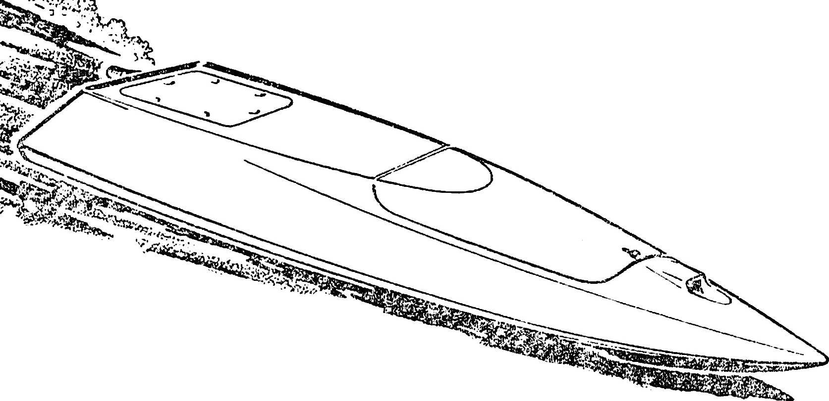
 Today, we first introduce you to the most massive representatives of the ship-class F1-V. This high-speed RC ships with engines working volume of 10 to 15 cm3. One of the most successful developments in this subclass is the model A. Baidebekova.