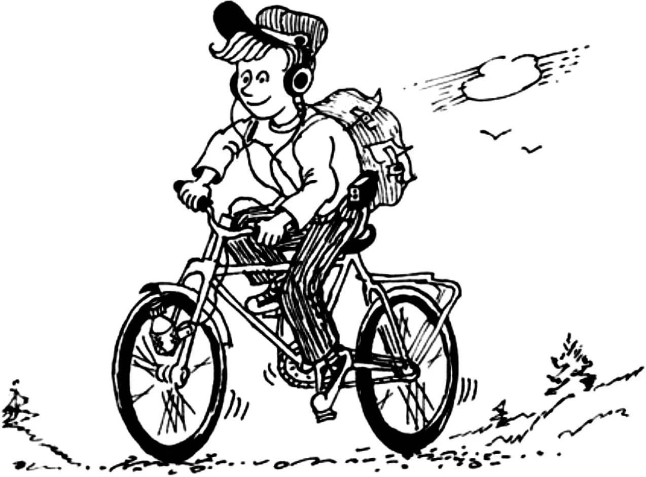
Improving drive efficiency is a problem that concerns not only bicycle designers, but also the owners of these machines.
Since the invention of the bicycle, the pedal drive has been brought, one might say, to perfection. Increasing its efficiency without complicating the mechanism is hardly possible. On sports and touring bicycles, for example, multi-speed transmissions are installed, but even in these drives there remains a so-called “dead zone,” when the cranks are near their vertical position. The pedals pass through this zone by inertia, because creating a full torque with the legs at that moment is very difficult.
The simplest solution to the problem seemed to be using an elliptical drive sprocket in the drive. Many years have passed since then, but somehow bicycle manufacturers do not appear to have taken advantage of this technical solution. Either they have not yet grasped the idea itself, or they are held back by technological difficulties.
I also have a variant for solving this problem. Only I changed not the drive itself, but only the rear-wheel fork — I built into it a hinged-spring mechanism that acts as an accumulator of potential energy. The hinge fully returns the energy of the effort to the drive precisely at those moments when the cranks pass through the “dead zones.”
I offer readers this tried-and-tested technical solution for increasing the efficiency of the pedal drive of an ordinary road bicycle, for which I received an inventor’s certificate.
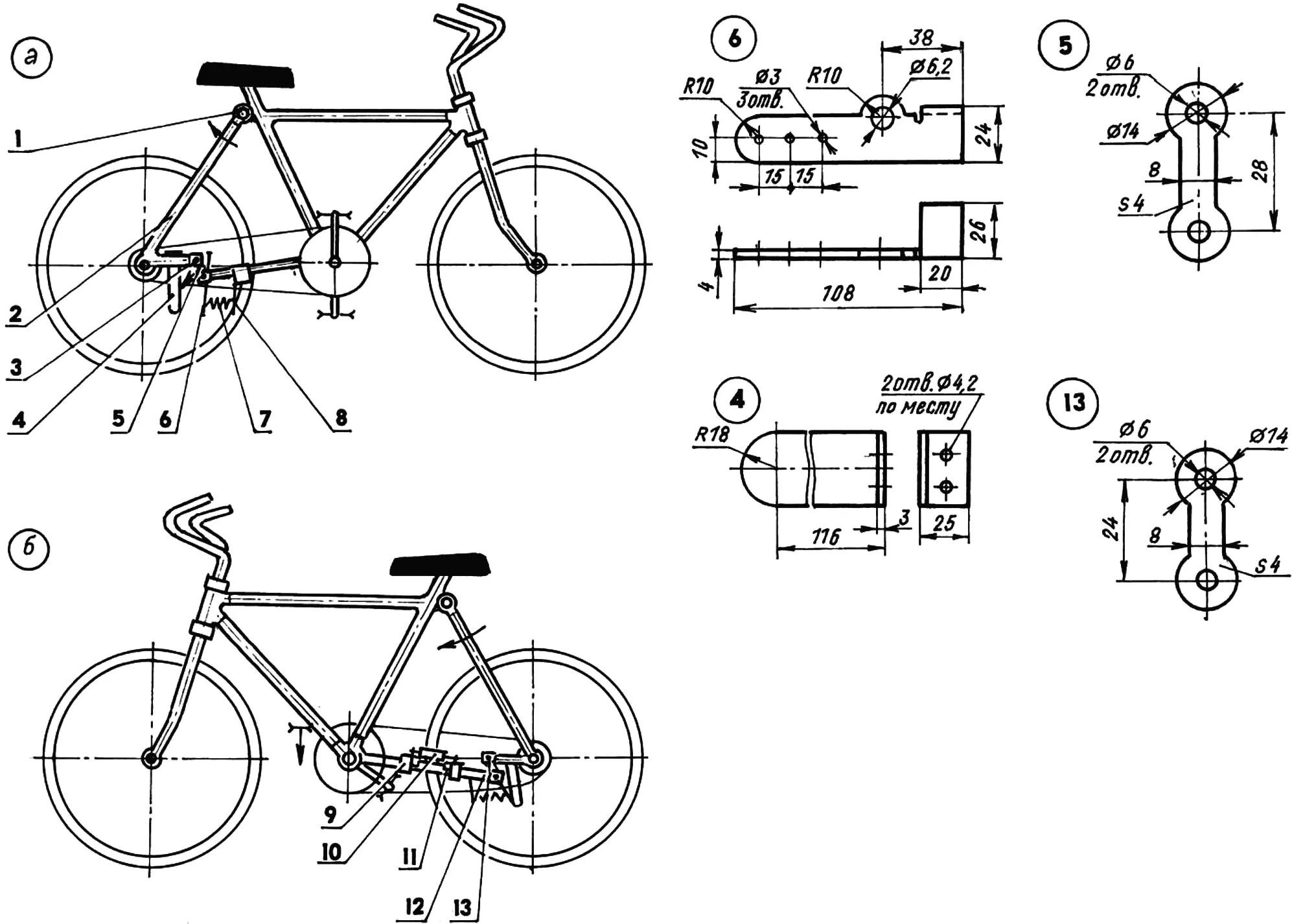
1 — hinged connection of the seat stays to the frame (M10 stud with nuts); 2 — seat stays; 3 — tip of the double hinge (4 pcs.); 4 — chain guide; 5 — right crank; 6 — two-arm lever; 7 — spring (normally compressed); 8 — bracket; 9 — clamp; 10 — limiting roller; 11 — bracket for mounting the roller axle; 12 — chain stays; 13 — left crank
First of all, about the changes in the bicycle design. They consist in the fact that the seat stays, at the point where they are attached to the frame (under the saddle), are now connected hinged by an M8 stud-axle. On older-model bicycles this is quite easy to do: the upper ends of the stays in the seat-stay joint are attached to the frame with a bolt, which need only be replaced with a stud-axle. On newer bicycle models, the upper welded ends will have to be cut off from the frame tube and holes for the stud drilled in them.
The chain-stay tubes are cut at about one quarter of their length from the wheel axle. At the cut, the stays are spread apart — the front parts are bent downward by distances equal to the distances between the holes in the cranks of the two-hinge mechanism (Fig. 1, parts 5, 13).
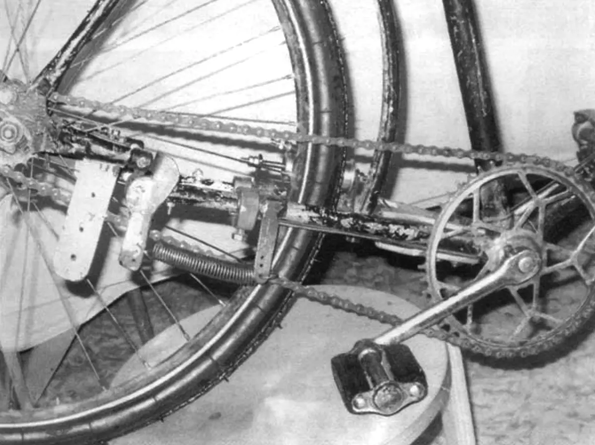
At the cut, a steel tip is inserted into the tube of each stay. Each of them is secured in the stay with two M4 bolts. In each pair of tips of one stay, a crank made of 4-mm steel sheet is fastened with M6 bolts, and the left crank is slightly larger than the right one. This ensures a more even movement of the cranks during their operation.
On the right side, a two-arm lever with an extension spring of 0.5–1 kg force is mounted on the lower crank axle. The other end of the spring is hooked onto a bracket pulled by a clamp to the front part of the stay. To adjust the spring tension, several holes are drilled along the length of the lever arm and the bracket.
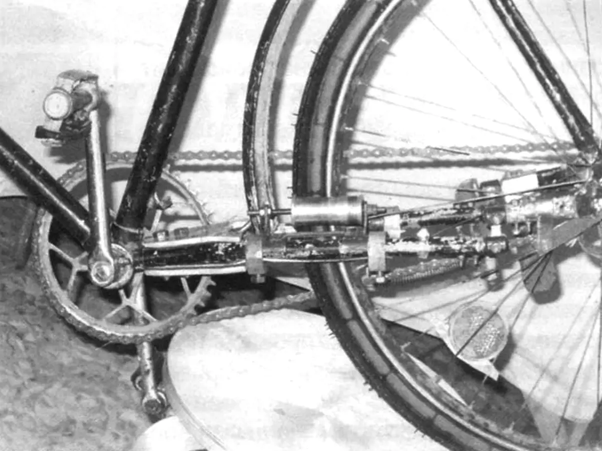
The device works as follows. In motion, when pressing on a pedal, the upper section of the chain not only rotates the sprocket of the driven rear wheel, but also pulls the wheel itself slightly forward, turning the cranks of the device. At the same time, the upper end of the right crank pushes the two-arm lever, which stretches the spring with its opposite end. This causes a slight rise of the rear part of the frame together with the saddle and the cyclist.
When the force is removed from the pedals (which also happens while they pass through the “dead zones”), the reverse stroke of the mechanism cranks and the wheel takes place under the pressure of the cyclist’s mass and the compression of the spring. In this case the chain slack is taken up, the sprocket with the driven wheel continues to rotate, and the cranks pass through the “dead zone.” In one full revolution of the crank, two such cycles occur.
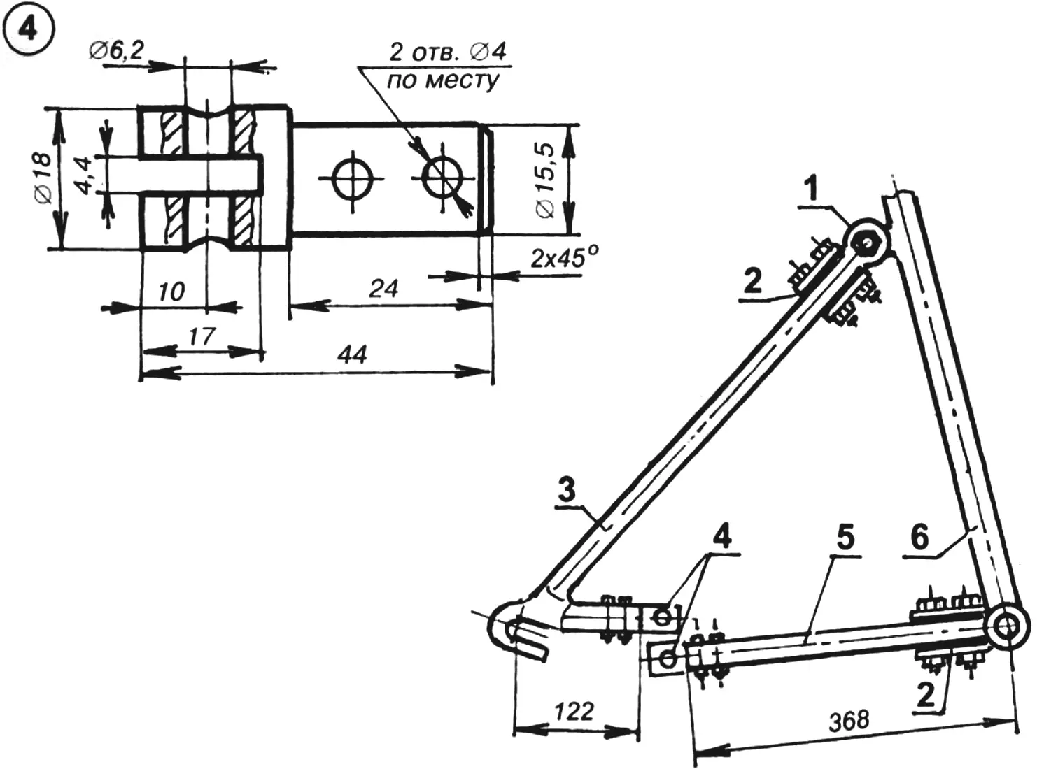
1 — hinged mounting of the seat stays to the frame; 2 — reinforcement of the root ends of the stays; 3 — seat stays; 4 — tips; 5 — chain stays; 6 — frame
Since during the forward movement of the rear wheel the lower section of the chain sags slightly, a chain-length compensator would be needed here. But it would inevitably complicate the mechanism design and require replacing the coaster brake with a hand brake. To keep the chain from jumping off the wheel sprocket when it sags, I installed a chain guide on the rear part of the right stay and secured it with the same two bolts as the tip mounted there.
One more thing. When transmitting a significant torque, the drive itself tends to turn the driven wheel counterclockwise (because the drive is located on the right side). With significant play in the hinged-spring mechanism (which is inevitable when making it at home), the drive succeeds in this, and the tire begins to rub against the left stay. To prevent this, a limiting roller is installed here.
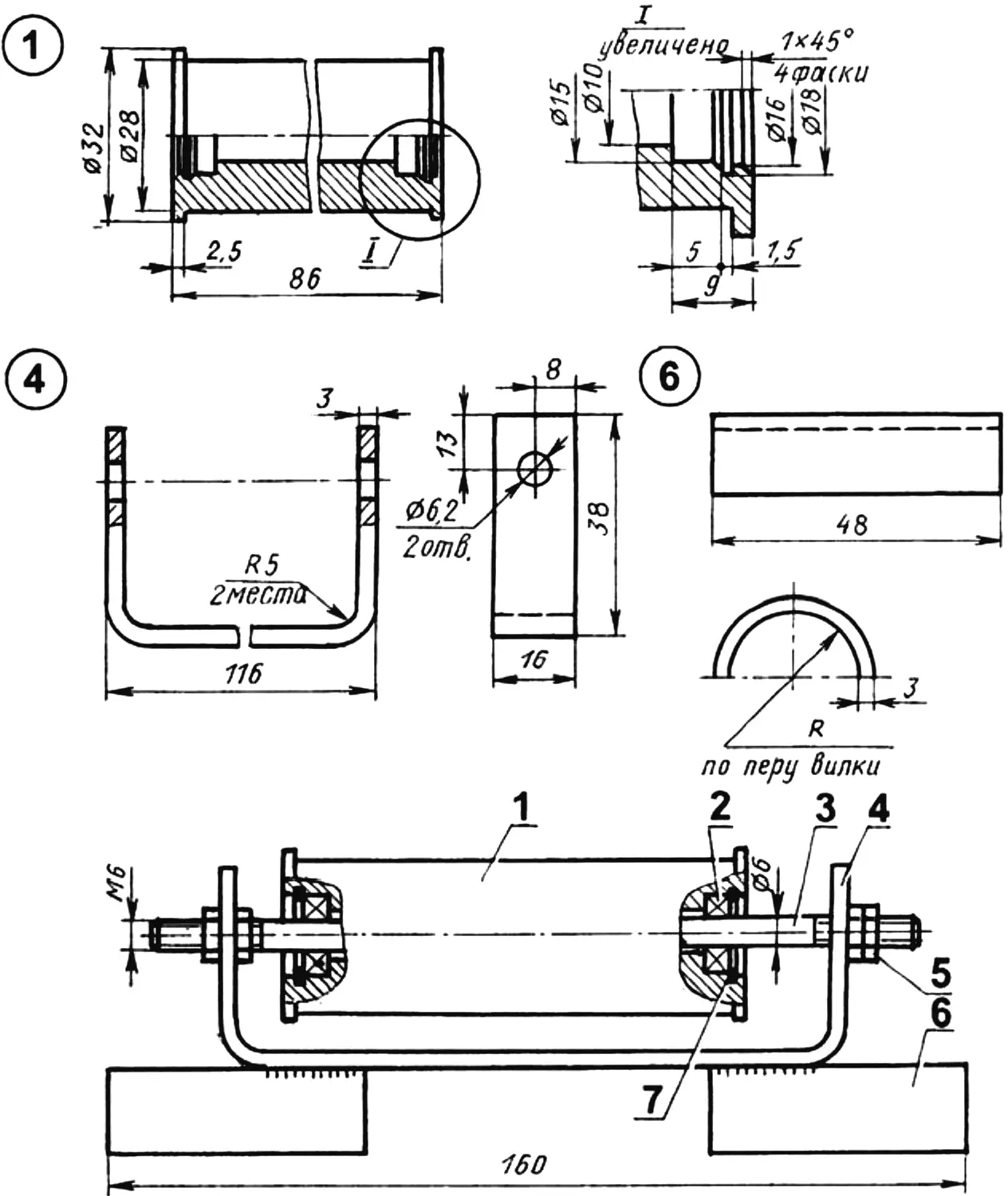
1 — roller (St3. bar Ø32); 2 — bearing series 1000096 (2 pcs.); 3 — axle (St3. M6 stud); 4 — bracket (St3, sheet s3); 5 — M6 nut (4 pcs.); 6 — support (St3. sheet s4, 2 pcs.); 7 — retaining ring (2 pcs.)
The roller is mounted on the axle on two bearings of series 1000096, although it would be more appropriate to install bearings of type 80000 or 180000 — with protective washers or seals, but I did not have any of those. The roller can move along the axle within the limits in which the hinge allows the rear wheel to move. The roller axle — an M6 stud — is installed in a bracket that is welded to two supports and fixed on the right stay of the fixed part of the chain stays with clamps and screws. I selected ready-made clamps, but they could also be made oneself — the same kind that plumbers install on water pipes when a leak needs to be fixed without welding.
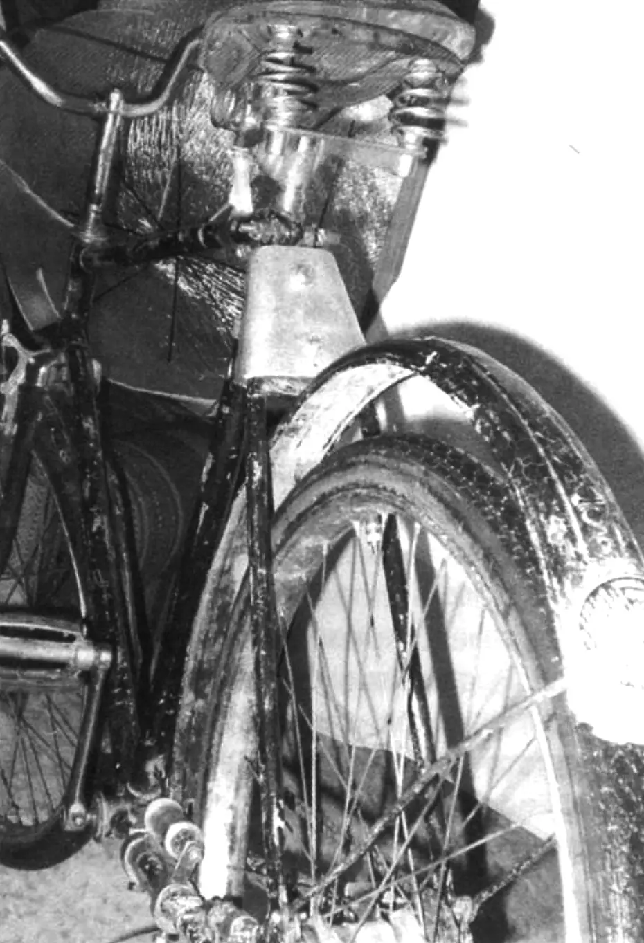
And finally. Since the designs of the seat stays and chain stays underwent changes and turned out to be weakened, I reinforced their root ends (joining the frame) with plates of 5-mm duralumin sheet with rubber gaskets, clamping each pair of plates with two M8 bolts.
I did not take special measurements of the increase in drive efficiency with the hinged-spring mechanism built into the frame, but by feel I assume that the cyclist’s work is halved. Riding such a bicycle even on a dirt road and heavily rugged terrain is pure pleasure.
“Modelist-Konstruktor” No. 7’2005, S. RESHETOV
Recommend to read
 RESTORING THE NOZZLE
The reasons of breakage of the nozzle on the Microdrive, a great many. And to do so more quickly, a new chiseled mikrodetal is not always possible. But, it turns out, engaged in the... EASY PRESERVING
Preparation for the winter vegetables, fruits and berries in many cases, connected with great inconvenience due to the imperfections of technology and primitiveness kitchen appliances...
