 The age of the members in the club of young technicians “planet” in the city of Izhevsk with a range from primary school students to graduates. And if the seniors are more interested in serious equipment (tillers, snowmobiles, ATVs, etc.), for the younger most attractive lightweight motorcycles, it was possible to start to ride. Therefore, the technical creativity of each new generation of young inventors usually begins with the development of mini-mokik. One of these machines has been described in the publication “Gasoline is not necessary” at No. 9 in 1997, “Model construction”. In it they talked about the design on the base frame and running gear from the Riga mini-mokik with motor drive MD-1 serial excitation. Unfortunately, this idea has not received development, as it was not possible to find a more lightweight, but powerful battery is a heavy car, which had to use in this design. Therefore, in the future to drive mokikov used traditional petrol engines type D-6, D-8.
Here on this development and will be discussed in this article.
Based on the mini-mokik took a regular children’s Bicycle (Fig.1). Given the difficult operating conditions (speeds of up to 60 km/h) frame and wheel of the future mokiki was strengthened. Between the seat and the steering pipes warily subframe from a pipe with a diameter of 27 mm. in addition to strengthening the subframe is the basis for fixing the gas tank of 2.5 liters. The rear part of the frame is strengthened by two alosinae from a pipe with a diameter of 12 mm On the front wheel instead of 12 regular spokes welded 6 steel strips with a cross-section 4×20 mm, 3 on each side (like the spokes). And on the rear wheel the number of spokes was increased to 32 as on adult Bicycle.
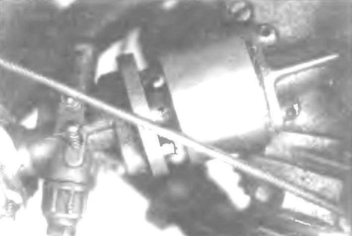
Mini-mokik set engine D-8. To increase the power inlet (between engine and carb) has placed additional valve (photo 1) and the height of the combustion chamber was reduced by 2.5 mm. the result is a 3 HP
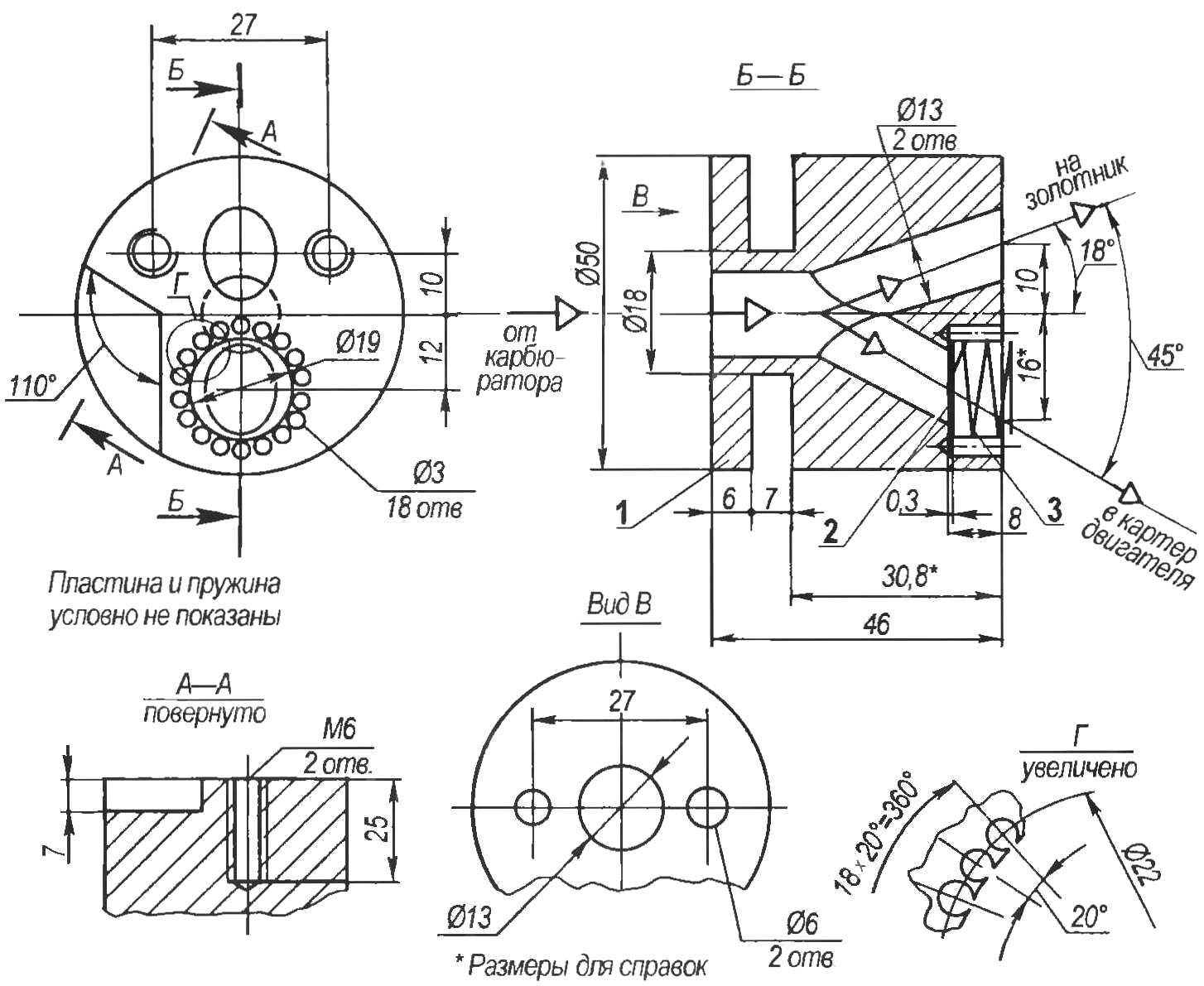
The valve body (Fig.2) is a cylinder with a diameter of 50 mm length 46 mm, made of duralumin D16T. In the case of drilled three channels with a diameter of 13 mm: the Central, facing the carburetor, and two oblique, which are included in Central. Part of the mixture from the carb on one of the channels goes directly on the motor spool and the other part on the channel on which you installed the valve, when the vacuum rushes into the crankcase. The damper plate (foil D16T 0.3 mm thick) with a lightly spring loaded to the side of the carb. Spring outer diameter 17 mm from a thin 0.2 mm wire 65G has 3 coils. Around the perimeter of the sample under the flap bored 18 holes with a diameter of 3 mm. These holes facilitate the passage of the mixture after opening of the valve. Occur when you bypass an additional amount of the mixture forms a overpressure in the compression chamber, creating the combustion of fuel plus the torque on the crank mechanism and thereby increasing engine power.
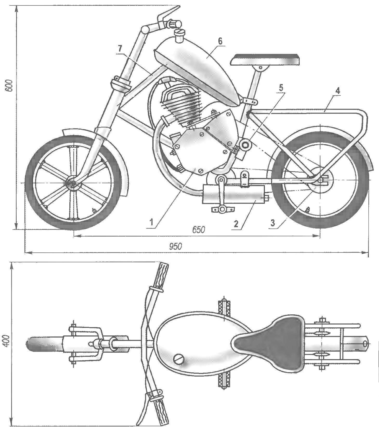
Fig. 1. Mini-mokik on the basis of a child’s Bicycle and engine D-8:
1 — engine D-8; 2 — silencer; 3 — counter shaft sprocket motor drive; 4 — kosina (tube Ø12, 2); 5 – tension pulley; 6 — a tank; 7 — the subframe (pipe Ø27)
Fig. 2. Valve:
1 — valve body (D16T); 2 — plate (foil D16T, s0,3); 3 — spring (65G wire, Ø0,2)
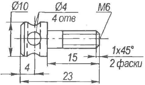
Fig. 3. Special bolt for fastening the valve to the cylinder of the engine D-8
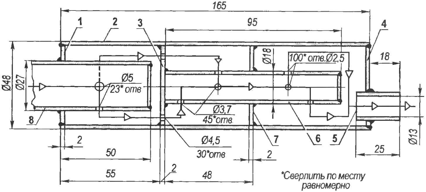
Fig. 4. Muffler:
1 — front end (sheet s2); 2 — housing (tube 48×2); 3 — perforated internal baffle (sheet s2); 4 — output end (sheet s2); 5 — the outlet (pipe 16×1,5); 6 — transition the inner pipe (pipe 18×1,5); 7 — deaf internal partition (sheet s2); 8 — reception pipe of the engine
Manufacturer of valve body should start with turning (to be turned to trim the ends, drill a Central hole to a depth of 15 — 16 mm, machined a groove width of 7 mm to 18 mm in diameter). Then mark the centers of the inclined channels, having sizes 10, 16 and 12 mm. Around the last center to a diameter of 22 mm spacing and severity 18 3 mm diameter hole to a depth of 9 — 10 mm, This operation should be carried out very carefully, as precisely as possible by maintaining the center-to-center distances as damage to the bridges between the holes (0.8 mm) may during operation lead to the breakage of the metal pieces, introducing them to a crank mechanism (CSV) and engine failure For the same reason, after the final machining of the valve body to remove the smallest particles of swarf should be blown through with compressed air and subsequent treatment with a vacuum cleaner and a magnet.
Before processing of the inclined channels in the ground marking their centres must severity 2-mm indentations with a diameter of 10 mm the part is firmly secured in the machine vise at an angle of 18° and two pass drills with a diameter of 6 mm and 13 to process the first channel (on the spool) to the exit in Central. (A better treatment of the channels in the valve to produce consistently drill, countersink and reamer. thus not only the accuracy but also the surface finish of the channels — Approx. ed.), Expanding the housing by 45° to drill the second (valve) channel. Then on a vertical milling or boring machine processing the recess under the plate and the spring boring head with a diameter of 19 mm (depth 8 mm), having dimensions of 12 mm (to the centre). In conclusion, to process the mounting hole and the recess (7×110°), which is necessary to accommodate the protrusion on the cylinder.
Mount the valve to the carburetor is carried out at its regular studs. But for interfacing with the cylinder had to manufacture special bolts (Fig.3, photo 1), so as to tighten the key bolts with regular hex head not have enough space. For sealing of the joint between the valve and the cylinder to apply heat-resistant sealant.
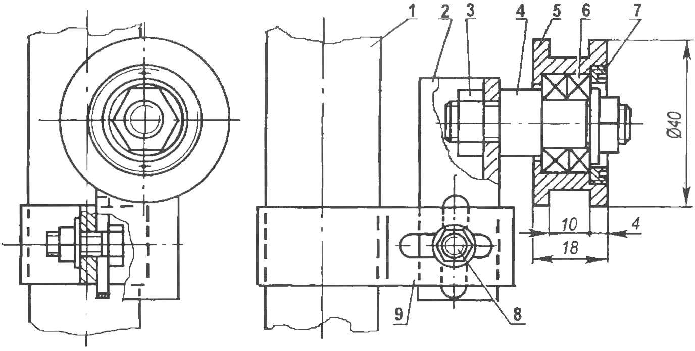
Fig. 5. Tensioner pulley:
1 — seatpost Ø27 pipe; 2 — roller bracket (area 20×20, L55), 3 — axis mount (nut M10 2 PCs); 4 — axis of roller (steel, lap 16); 5 — roller (steel 40X, lap 40); 6 — bearing 1 900 000 (2); 7 — lid (steel, sheet s3); 8 — mounting bracket (M6 bolt); 9 — clamp (steel, strip 2×20)
Photo 1. Additional valve between the carburetor and the engine D-8
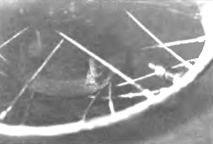
Photo 2. Mount the sprocket on the rear wheel bolts M6 with segment goals
Regular engine muffler D-8 replaced with a new one (Fig.4), improvised with the case of thin-walled tubes with an outer diameter of 48 mm. In muffler, 3-chamber Exhaust gases via the holes 23 with a diameter of 5 mm at the end of the admission pipe of the engine, welded to the input end of the muffler, into the first compartment. Out through the perforation (30 resp. 4.5 mm) to the first internal partition in the second compartment. And the third internal conduit 45 through the inlet holes with a diameter of 3.7 mm and 100 outlet diameter of 2.5 mm.
And the last stage of the exhaust — from the third compartment to the outside through the outlet of the New muffler has lowered the sound volume, though slightly, but still raised the power and maximum engine speed.
Drive to the rear wheel mokik is a roller chain with tensioning roller (Fig.5) using a homemade 24-bevel star, made of steel sheet with a thickness of 4 mm, grade 40X. Roughing was carried out by marking on the vertical milling machine AA 4-mm cutter, final — round file the Asterisk is attached to the flange of the rear wheel bolts M6. Side spokes has a special segment washer with a rubber gasket, like a motor bike (photo 2).
Start mini-mokik from the rotation of the pedals.
Technical characteristics
Engine power, HP…………………………..3
Maximum speed, km/h……………….60
Weight, kg………………………………………………..22
R. CHEREPNEV, syut “planet”, Izhevsk
Recommend to read
 PEUGEOT 307 CC
In November 2001, 55 journalists from leading automobile magazines that were part of the international jury, called the PEUGEOT 307 "European car of 2002". Has not passed also two years... VOLTAGE CONVERTER
On occasion purchased a portable led flashlight in China with the battery inside. The flashlight has the ability to switch between a cluster of eight super-bright LEDs and a krypton bulb...