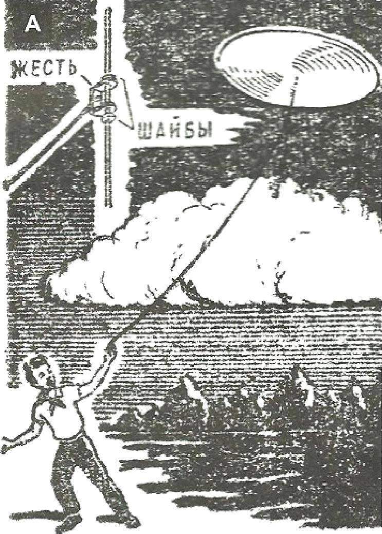
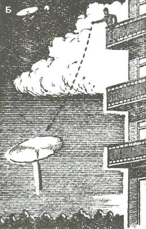
This principle is incorporated in the gyroplane during takeoff on the runway its rotor under the action of the oncoming flow starts to spin and gradually develops lift sufficient for take-off. Therefore, the rotor – rotor performs the same role as the wing of the aircraft. But compared with wing, it has the advantage that its forward speed equal to the lifting force can be much smaller. Because of this gyroplane is capable of fall in the air almost vertically and land on small platforms (Fig. 2). If the take-off to spin the rotor blades at zero angle of attack, then rapidly transfer them to a positive angle, the gyroplane can take off vertically.
Fig. 2. Gyroplane at low speed takes a load from the ground
WHAT FLEW I. BENSEN
The prototype of the most Amateur glider-gyroplane was the car of American I. Benzene. It was created shortly after the Second world war and aroused great interest in many countries. According to official data, currently built and successfully fly more than a few thousand units of this kind.
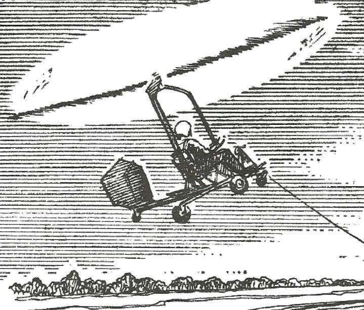
Gyroplane I. Benzene consists of a cruciform metal frame A, which is rigidly mounted pylon B, which supports the rotor with lever direct control of the City Before the pole is the seat D, and the rear on the frame – a simple vertical tail, consisting of E keel and rudder Z. the Latter is connected by cables with a foot pedal located in the front part of the frame. The chassis of the gyrocopter – a three-wheeled, pneumatic type lightweight (side wheels have a size of 300×100 mm, front, controlled – 200×75 mm). Under the rear part of the frame is additional support wheel of solid rubber, diameter 80 mm., the Rotor has a metal hub and two wooden blades describing a circle with a diameter of 6 m. the Chord of the blade is 175 mm, the relative profile thickness is -11%, the material is high quality wood and-stick plywood reinforced with fiberglass. Flying glider-gyroplane of Benzene was carried out in tow behind the car (Fig. 5). Subsequently, a similar machine was mounted 70-HP engine with a pusher propeller.
Fig. 3. Scheme microstoria Igor Bensen (drawing made by the designer)
Fig. 4. The scheme of the glider-gyroplane (winopener) designed by A. Bobik; H Jyrki and A. Sokal
Fig. 5. Modern microalloy, towed car
Polish designers Alexander Bobik, Czeslaw Yuri and Andrei Sokal created a glider-gyroplane (Fig. 4) taking off from water. It was being towed by high speed boat or motor boat with a powerful outboard engine (50 HP). The glider is mounted on the float shape and design are similar to case sports scooter Junior classes. Rotor with direct control mounted on simple and light pole raskalennoy mechanical rope stretch marks to the body of the float. It is possible to achieve minimum weight design with sufficient reliability. Technical data glider-gyroplane, which its authors called “bioplaneta”, are as follows: length – 2.6 m, width 1.1 m, height -1,7 m, total weight – 42 kg, a rotor diameter of 6 m. Its flight data: takeoff speed of 35 – 37 km/hour, maximum allowable is 60 km/h, landing – 15 – 18 km/h, rotation frequency of the rotor – 300 – 400 rpm.
Polish designers made their “winopener” a lot of successful flights. They believe that their car has a great future. One of the creators of “bioplaneta”, Czeslaw Yuri, wrote: “While respecting the basic rules of care, high discipline of the driver of the boat and staff the flight in the “winopener” absolutely safe. A large number of lakes, water surface which is always free, will allow you to pursue this fascinating sport and recreation for everyone”.
CONTROL SYSTEM
Understand how to ensure the controllability of the machine. On the plane it’s just – there are no elevators, rudder and ailerons. Deviation them in the right direction are any of evolution. And rotary-wing machines, it turns out that such rudders are not needed: change of direction occurs immediately, as soon as the axis of the rotor changes its position in space. To change the inclination of the axis of the rotor glider-gyroplane applied a device consisting of two bearings; fixed in her cheeks And head, and connected with the control lever B. A Bearing, being spherical, allows the rotor shaft to deviate from guideline 12° in any direction, which ensures the machine longitudinal and lateral control.
Lever rotor rigidly connected with the housing of the lower bearing, is reminiscent of the Bicycle handlebar crossbar, which the pilot holds with both hands. For takeoff, to move the rotor by a large angle, the lever moves forward; to reduce the angle and translation of the machine in horizontal flight – ago; to create a roll to the right (or correct the left roll) lever tilts to the left, right roll to the right. This feature of the control gyros creates some difficulties for pilots flying conventional gliders, aircraft and helicopters (traffic handle all of these machines is opposite in sign).
Therefore, before flying on llanerch-the gyro with a direct control need to undergo special training for the stand simulator. You can, however, go for a more complex structure, equipping the car is running “normal” aircraft type (shown by the dotted line in the diagram, the gyroplane Benzene, see Fig. 3),
BEFORE BUILD
Glider-gyroplane has significantly less parts than a normal Bicycle. But this does not mean that it is possible to make somehow, in one spot tied with wire and the other is a bolt to insert the nail.
All items must be made, as they say, at the highest level of aviation because of their quality, their reliability depends on a person’s life. Even if flying over water. That’s why you should make such a decision: it is possible to perform all the work of high quality – will do airoplanes – if not, postpone the construction until better times.
Fig. 6. The design of the blade
Fig. 7. The batch
Fig. 8. Gluing in the stocks
The most important and difficult part in the manufacture of bioplaneta is, of course, the rotor. Attempts to use for installation on homemade gliders gyroplanes overage blades are manufactured from our industry helicopters did not succeed, as they are designed for other modes. Therefore, to apply them in any case should not be. Standard design of the blade shown in figure 6. For bonding of the spar need to prepare straight grained, well-dried pine slats and carefully pripojovat them to each other. They are going in the package, as shown in figure 7. In the gaps between the slats definitely laid strips of fiberglass brand АСТТ6, pre-coated epoxy adhesive. Reiki should also be coated on both sides. Package after the necessary exposure is pressed in the fixture, providing product straightness by broad and narrow side of the package. After drying, the packet is processed in accordance with a given profile forming the front part (the”nose”} of the blade. Treatment should be performed very carefully using steel kontrabaev. The “tail” of the blade is made from blocks of Styrofoam brand PVC-1 or PS-2, reinforced next to the plywood ribs. Gluing should be performed in a special stocks (Fig. 8) to ensure correct profile. Final machining of the blade is with a file and sandpaper, using kontrabaev, after which the entire blade is glued a thin glass fiber with epoxy glue, sanded, painted in bright color and polished first paste, and then polishing the water.
Ready the blade, put the ends on two supports, shall withstand not less than 100 kg static load.
To connect with the hub of the rotor for each blade six M6 bolts reinforced steel plate, as shown in the drawing; in turn, the hub and these plates are fixed with two bolts M10. Trimmer d, and the weight of counterweight G are installed on fully finished blade. Cargo – three M5 bolts, trimmer – five rivets with diameter 4 mm. In “shank” blades for Prilepko trimmer pre-pasted between the plywood ribs and wooden boss.
The spherical bearing of rotor head on foreign designs selected in the range from 50x16x26 diameter mm diameter mm 52x25x18; domestic bearings of this type can be applied No. 126 GOST 5720-51. In the diagram (Fig. 4) this bearing is shown for illustration purposes single. The lower bearing control No. 6104 GOST 831-54.
Fig. 9. Constructive drawing of the housing of the float glider-gyroplane and drawings of major sites
Fig. 10. Towing lock:
A – base; B – hook; – a installation of the lock on the glider-gyroplane (hook down); G – lock installation on the boat-towing (hook up)
Autogyro”, Bensen In 8 m”
Simplicity of design is characteristic of the gyros I. Bensen
Igor Bensen
Mount the control arm to the bearing housing may be performed by the staples, as shown in figure 4 (it is possible to disassemble the whole unit to the individual elements), or by welding.
Base (“heel”) of the pylon is fixed in the housing of the float to the stiffening rib, connected by four M6 bolts with the keel. These bolts simultaneously attached to the body of the float exterior metal pen. Ropes connecting the pylon with the sides of the float, preferably before tabletkoy to fit with a force of 150 – 200 kg the Turnbuckles aircraft, with the thickness of the threaded bars 5 mm.
As mentioned above, a lot of bioplaneta should be kept in the range of 42 – 45 kg. It is not as easy as it seems at first glance. You need to very carefully pick up the necessary materials to properly conduct the machining and Assembly, not to use heavy fillers and paints. This particularly relates to the manufacture of float. The wooden frame must be built of well dried strips of straight grained, lightweight (not resinous) pine. The best wood for the frame of the float is the so-called “aviation” pine monitors in the bars, but its not everywhere and not always you can get. Therefore, you should not neglect the possible substitutes: for example, a good container with a Board or slats sawed from thick slabs (a slab is the sapwood, the most solid part of the trunk; with the right cut of it make great strips of desired cross-section). Often food canned goods are Packed in good boxes. Typing two or three dozen such elementary plates, one can select the desired. Each rail prior to installation on site must be tested for strength. If broken – it doesn’t matter, you can put another; but there was full confidence that the set is made of reliable material.
G. MALINOWSKI
Recommend to read COUNTRY TURNTABLES Favorite home gardeners have always been turntables rattles, driven in rotation by the wind — they are designed to repel moles and other rodents that can damage the roots of the garden... MISSILE “STORM” In accordance with the existing plan for the construction of the Soviet Navy in the late 1950-ies provided for the construction of a series of special vehicles, air defense PR 1126 ships... 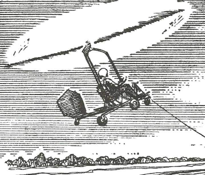
 In recent years, the aviation enthusiasts in many countries are showing great interest in flying on makeshift gliders-the gyros and the gyros. Inexpensive, easy to manufacture and easy to pilot, these aircraft can be used not only for sports but also as an excellent way to familiarize wide circles of young people with the element of air. Finally, they can be used for communication. In 1920 – 1940th years, gyros were built in many countries. Now they can be seen only in museums: they could not compete with helicopters. However, for sporting purposes the gyros and especially towed gyroplanes-gliders are used in our days (see figure).