If someone had told the author some time ago that he would have to literally “reinvent the bicycle,” he would have taken it as a joke. However, that skepticism vanished after coming across a magazine article describing a “wind vehicle” built by Alexander Dvoynikov. The model had both air and propeller screws mounted on an inclined shaft and moved strictly against the wind — powered by… the wind itself!
It seemed tempting to build a one-person wind-powered craft based on the same principle: two bicycle wheels, if their spokes are paired and covered with dense fabric, could serve as multi-blade wind turbines, driving a propeller via a chain transmission.
But what to do when there is no wind? You can pedal the wheels! In this case, the wheels act as air propellers, and the propeller at the rear works as usual. However, such a transmission would be too complex and result in significant energy losses.
What if we used a regular land bicycle for movement on water?
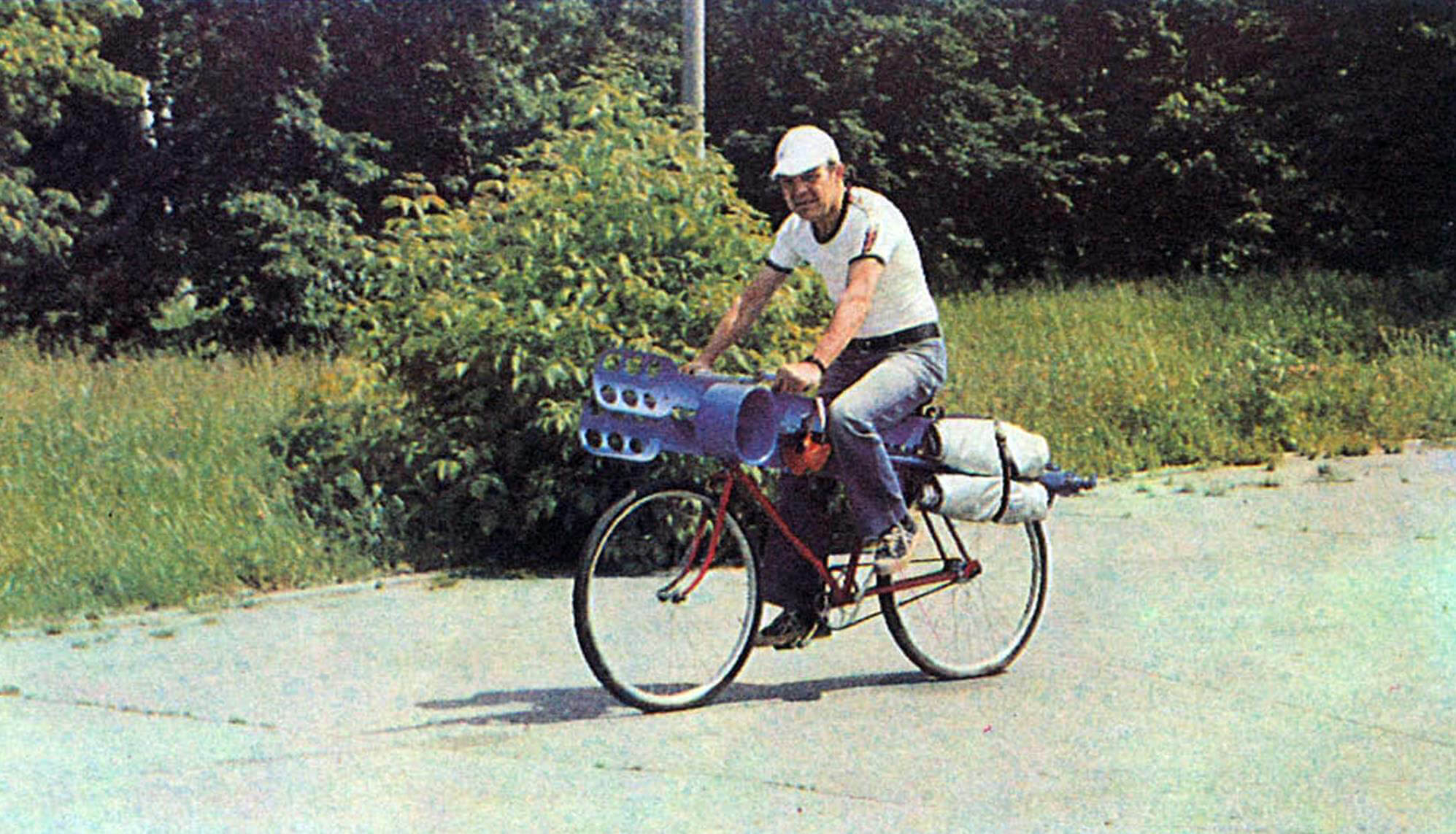
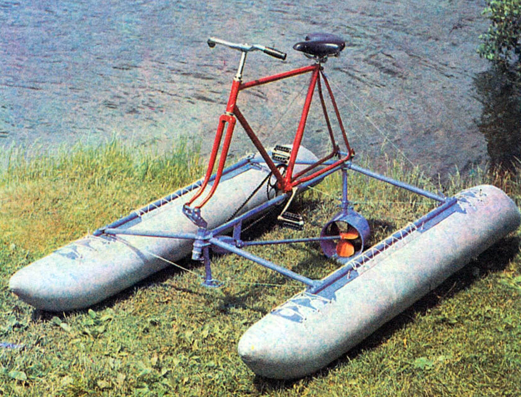
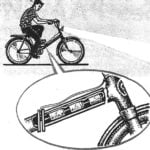
Eventually, this idea evolved into a design now presented to the readers. It is an add-on module for a road or touring bicycle. When riding on land, the structure is folded, covered, and attached to the bike frame from the side.
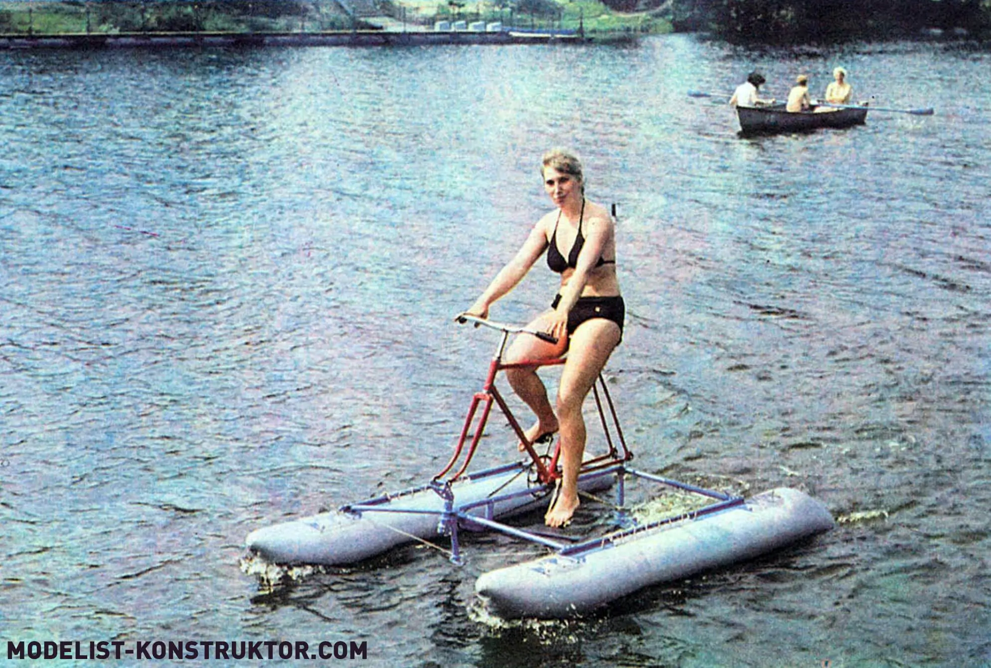
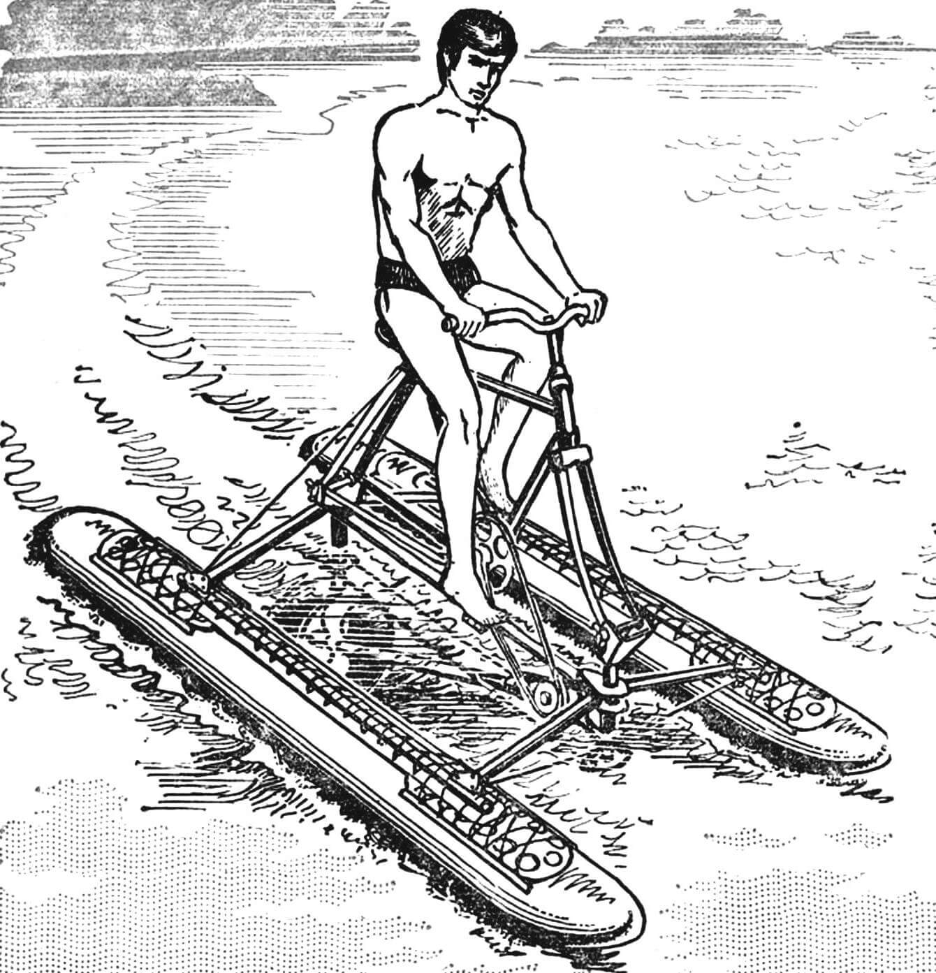
Once at the water’s edge, the add-on is unfolded, the bicycle frame (without wheels) is mounted onto it, the floats are inflated — and you’re ready to cross the English Channel, the Bay of Biscay, or even the “furious fifties,” provided you take the wheels with you. But seriously, this amphibious bicycle is ideal for countryside rides, water recreation, camping, and fishing trips.
DIY enthusiasts wishing to build this add-on will need several meters of duralumin tubing, a steel cable for the frame, and 6–7 m2 of waterproof fabric for the floats. If you live near a body of water, you can even create a fully aquatic vehicle — a “hydro-bike” — based on a wheel-less bicycle frame.
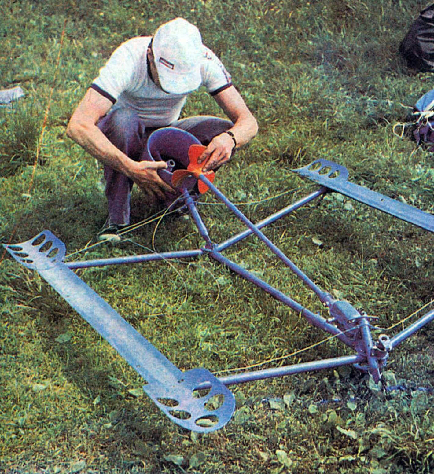
The add-on consists of a load-bearing frame, inflatable floats, and a screw-type propulsion unit. The main structural element of the frame is the central beam, with longitudinal beams hinged to it via crossbars. Below, front and rear folding struts are installed to act as braces for the guy wires connecting the ends of the crossbars. The outer ends of the rear crossbars are guyed to the bicycle frame, preventing it from tipping over and keeping the crossbars from folding back.
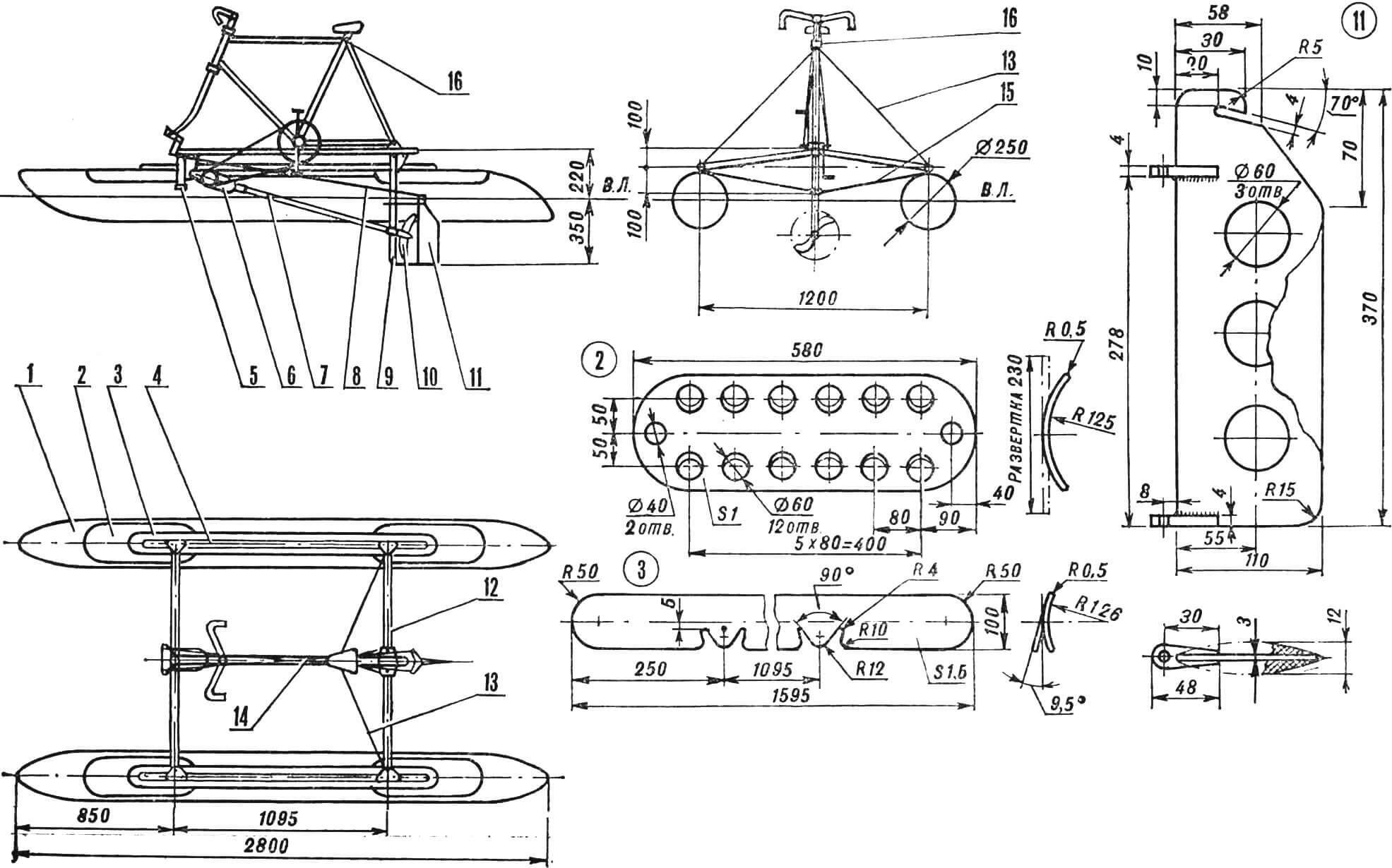
1 — float, 2 — plate, 3 — saddle, 4 — longitudinal frame beam, 5 — front vertical strut, 6 — gearbox (hand drill), 7 — propeller shaft, 8 — steering drive, 9 — rear vertical strut, 10 — propeller, 11 — rudder, 12 — crossbeam, 13, 15 — guy wires, 14 — bicycle frame, 16 — lock.
To transfer load from the frame to the floats, saddles with removable plates are riveted to the bottom of the longitudinal beams. The floats are laced through tabs or secured with hook-and-loop fasteners.
The propulsion unit includes the gearbox, propeller shaft, propeller, and the rudder behind it, which is connected to the bicycle’s front fork via special wiring. Front and rear attachment points for the bike are located at the ends of the central beam.
The design and assembly of all listed elements may vary depending on available tools, skills, personal taste, and creativity of the builder.
Despite the attempt to keep things as simple as possible, the author could not avoid lathe work and welding — necessary for making the mechanism as light as possible while ensuring sufficient strength and rigidity.
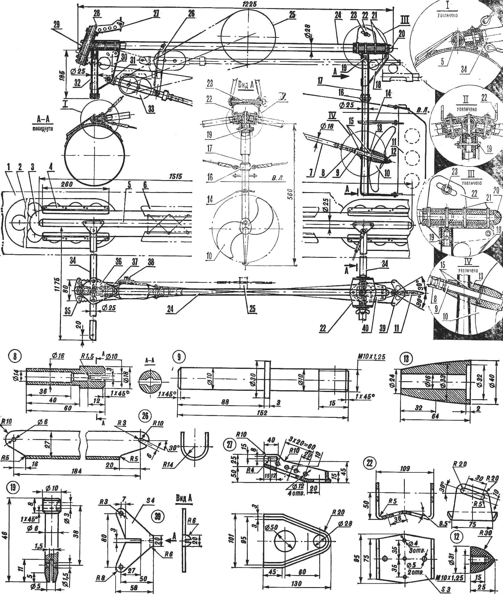
1 — float, 2 — plate, 3 — saddle, 4 — guide tab, 5 — longitudinal beam (Ø 25X1.5 mm tube), 6 — valve, 7 — propeller shaft (Ø 18X1 mm tube), 8 — shaft tip, 9 — shaft axle, 10 — propeller, 11 — rudder, 12 — nut (textolite), 13 — bearing housing, 14 — anti-cavitation plate, 15 — bushings (PTFE, caprolon), 16 — nozzle, 17 — rear strut, 18 — rear bracket, 19 — removable pin, 20 — plug, 21 — rivets, 22 — bracket, 23 — screw with wing nut, 24 — central beam (Ø 28X2 mm tube), 25 — bicycle sprocket, 26 — pivot strut, 27 — front bracket (top view omitted), 28 — bracket axle (Ø 28X3 mm tube), 29 — bushing (Ø 34X2.5 mm tube), 30 — pivot bracket, 31 — fork, 32 — front strut (Ø 25X1.5 mm tube), 33 — gearbox (hand drill), 34 — crossbeams, 35 — rocker arm, 36 — front upper brace, 37 — front lower brace, 38 — gearbox sprocket, 39 — rudder arm, 40 — rear brace.
Power Transmission. A two-speed hand drill with a 7:1 gear ratio is used as the gearbox. Along with the chain drive, it provides a total transmission ratio of 21:1 between the pedal crank and the propeller. The drill is mounted using the fork axle. The side handle is replaced by a small chain sprocket fitted onto the hex shank, and the chuck is replaced with the propeller shaft.
To improve efficiency, the originally used three-blade Ø 200 mm propeller was replaced with a two-blade Ø 270 mm version, laminated from fiberglass with epoxy resin. It is a left-hand propeller with a pitch of about 230 mm. The shape and thickness of the blades were selected so that the blade angle changes elastically with load, providing nearly optimal pitch in all operating modes.
The propeller can also be made of metal or adapted from an existing one — for example, from the “Veterok-8” or “Veterok-12” outboard motor.
To simplify the design and reduce the size of the folded add-on, the originally planned duct ring around the propeller was omitted. Instead, a lighter anti-cavitation plate was installed to prevent air suction.
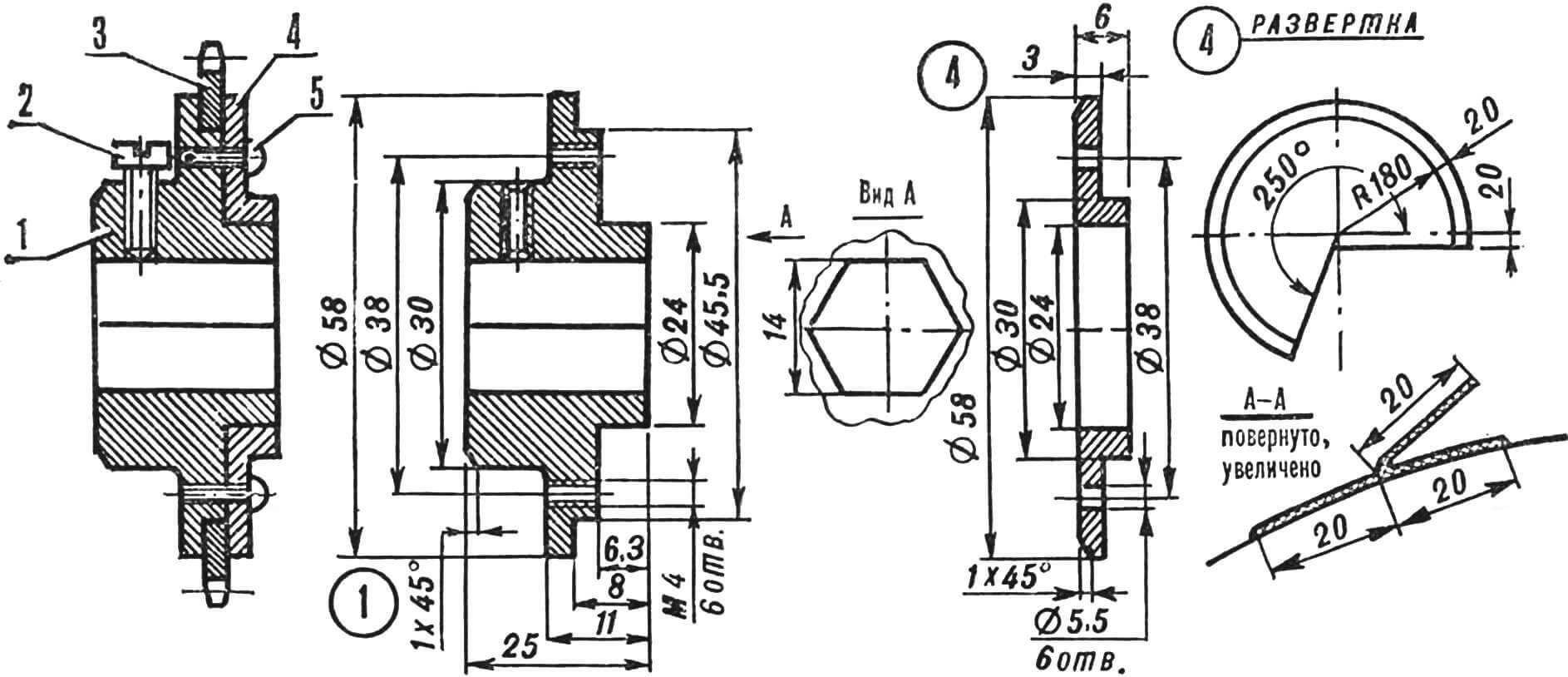
1 — housing, 2 — M6 locking screw, 3 — bicycle sprocket ring Ø 80 mm, 4 — cap, 5 — M4 screw.
The support bearing of the propeller shaft contains PTFE bushings that can operate in water without lubrication (alternatively, caprolon may be used).
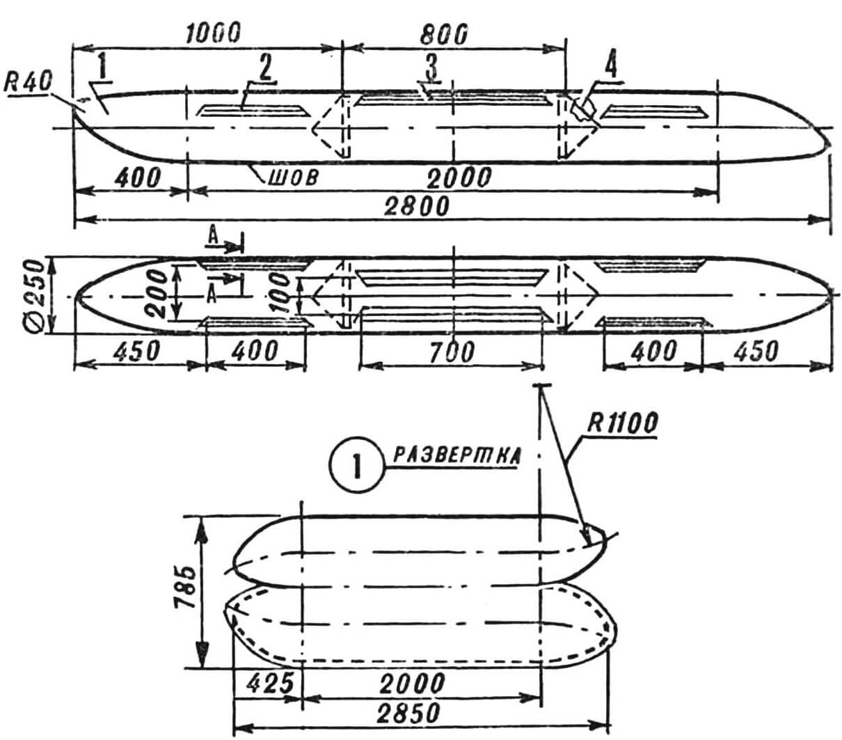
The inflatable floats are cut from rubberized fabric (known as “silver cloth”). To improve airtightness and protect the cotton base from getting wet or decaying, the reverse side is coated with two layers of 51-G-10 sealant, diluted with B-70 gasoline in a 1:1 ratio.
For floats, nylon or lavsan fabric impregnated with sealant 51-G-10 or U-30MES-5, polyurethane, or “Moment-1” glue diluted with turpentine in a 1:1 volume ratio is also suitable.
1 — shell, 2, 3 — tabs, 4 — diaphragm.
To attach the floats to the cradles, tabs are glued from a strip of the same fabric, 80–100 mm wide, folded as shown in the diagram. It’s better to glue the tabs to the inflated floats, aligning them with the prepared cradles and plates.
If the floats are to be laced on, drill holes in the tabs with a diameter of 10 mm and spacing of 80–100 mm. Then insert spokes made from duralumin electrodes with a 3 mm diameter through the tab loops.
To increase the survivability of the cycle amphibian, each float is divided into three compartments by transverse bulkheads made in the form of conical diaphragms from the same fabric. This shape holds well under pressure and allows the floats to be rolled up without folds. Install the bulkheads last, leaving an open seam section about half a meter long in the center of the float for this purpose. It’s best to place this seam at the bottom.
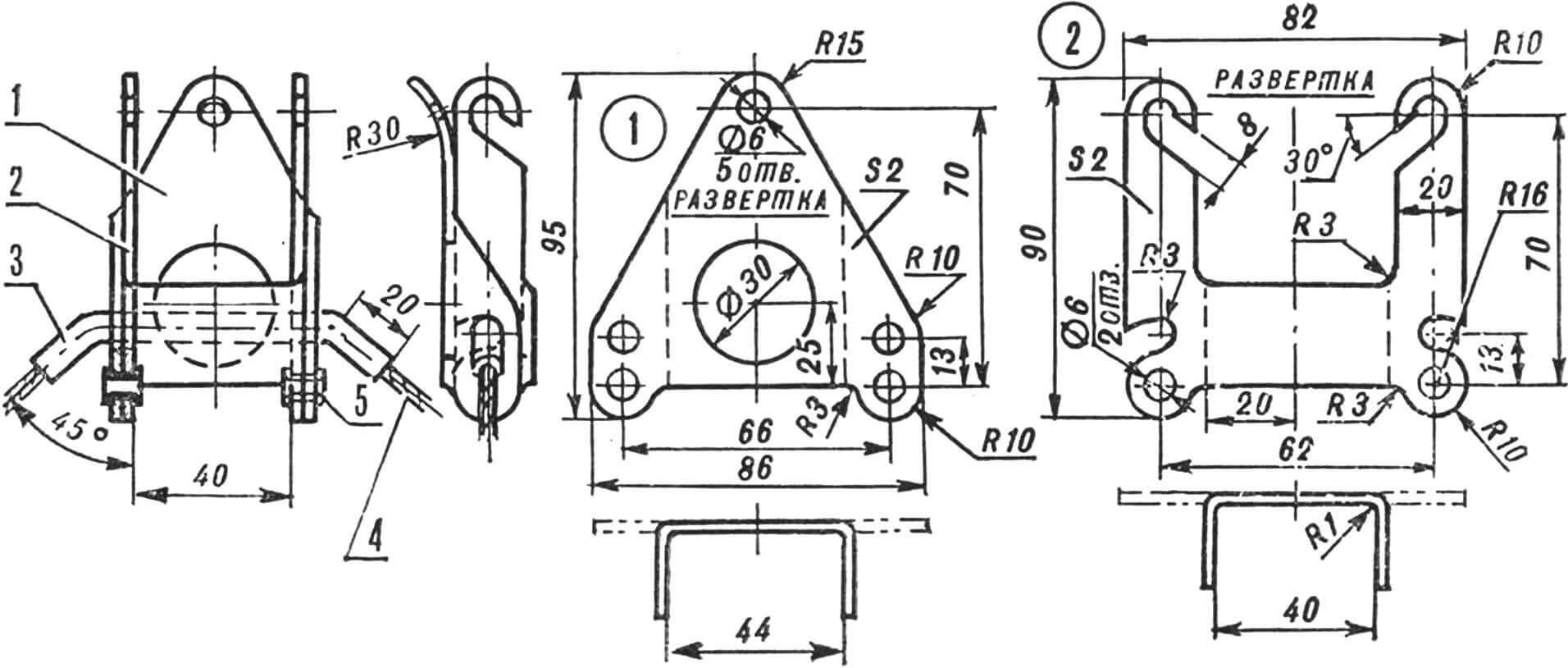
1 — housing, 2 — double hook, 3 — tube Ø 6×1, 4 — upper brace, 5 — tubular rivets.
Inflating the floats with air is easy using a rubber pump (frog). Don’t forget to glue valves with removable nipples from a rubber boat into each compartment of the float.
It’s best to form the float ends on a mold, which can be made from foam, wood, papier-mâché, or clay. After assembly, all seams should be sealed with a sealant and then reinforced on the outside with fabric strips 20 mm wide.
To improve airtightness, enhance appearance, and make the floats water-repellent, they are painted with an elastic paint made from the following mix: one tube of “Moment-1” glue, 0.5 liters of turpentine, and 100 g of aluminum powder.
Finally, a few words about further improving the design. In principle, it’s possible to replace the drill and angled shaft with a vertical column, eliminating the rudder. This would reduce weight and dimensions and remove the need to disconnect the chain. It’s also worth trying a fin-type propulsion system instead of a propeller. And finally, create an attachment that doesn’t require removing the wheels.
FOR WATER RIDES AND TOURISM
The main advantage of the design developed by Gorky resident A. Safronov is its dual-purpose nature — it can be used both on land and on water. The secret lies in a special attachment — a float catamaran — that’s fitted to a regular bicycle. When folded, it forms a compact package that fits on the same bike, and assembling the amphibike takes only a few minutes.
TECHNICAL SPECIFICATIONS
Net weight of amphibike, kg — 26
Load capacity afloat, kg — 100–120
Float volume, L — 256
Water speed, km/h — 8–10
Overall dimensions, mm:
— amphibike on water — 2800×1450×1250
— folded attachment — 2000×250×150
A. SAFRONOV
Recommend to read
 THE BATTERY IN THE FRAME
When equipped with a headlight of a Bicycle "Salyut" there is no need to manufacture special container for batteries. It can be hidden directly in the frame, pre-SPAW three elements 343...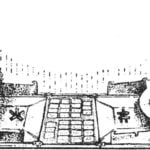 SKITTLES ON THE TABLE
Old Russian game gorodki beat always popular. Many fans of this popular sport attracts it today. Our reader A. Zhdanov from Feodosiya has developed its desktop version, which is no less...
