Because the engine power was only 10 HP, it was a topical task of securing a small mass of all additional mechanisms and components of the future Rover.
Rear axle is the most complex knot of potopalskogo. He, like front fork, made modular, that is mounted instead of the rear wheels and pendulum fork without any alterations to the motorcycle.
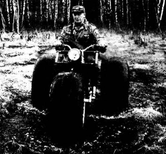
Basic motorcycle
Rear axle along with the intermediate shaft assembled in its own frame-fork welded from square tube 40x40x3 mm. In the front part welded to the frame transverse sleeve, made according to the dimensions of the sleeve of the pendulous fork rear wheel of the motorcycle. Width the rest of the frame is made such that between its feathers fit the differential rear axle. The lower struts-crossmember that holds the axle to the frame, made of 25×25 mm area, the upper — half-inch pipe, flanges from a steel sheet with a thickness of 2 mm and with a vertical flange.
The bridge itself, or rather its internal components without cover, UAZ. His axle shortened and welded, and instead of a crown of the planetary bevel gear is mounted 45-bevel sprocket from a motorcycle “IZH”. At the ends of the axle shafts is made the keyways (the grooves in the hubs of the tires), and at the ends — threaded holes M10 for screws of fastening of a wheel.
Rotation of the sprocket of the rear axle from the engine is transferred by two gear chain via intermediate shaft. First chain transmission from the output shaft of the motorcycle engine for a big 41-bevel sprocket in increments of 12.7 mm on the intermediate shaft. Second gear — from a small 17-bevel sprocket mounted on the other end of the intermediate shaft, 45-bevel with a step 15,875 mm rear axle.
Rear axle:
1 sleeve (steel pipe 3/4″); 2 — the frame-fork (steel pipe 40×40); 3 — brake drum with sprocket (z=41, t = 12,7, from the Minsk motorcycle); 4 — axis intermediate shaft (the shaft from the Minsk motorcycle); 5 — intermediate shaft (the hub of the rear wheel of the Minsk motorcycle with a bearing of 203); 6,17 — lower struts (area 25×25,4 items); 7 — upper brace (pipe 1/2″); 8 — clamps-ladders M8 (rod 08, 4x); 9 — differential (UAZ-469); 10 — rear chain (t = 15,875); 11 — housing with bearing 80209 (2); 12 — the dust cover; 13 — a housing with a bearing 206; 14 — drive shaft (shortened from UAZ-469,2 PCs); 15 — screw M10 washer securing the wheel hub (2 PCs); 16 — tensioner rear chain (2 PCs); 18 — flange installation rear axle (steel, sheet s2,2); 19 — lugs securing the right of the additional absorber (STZ, sheet s2); 20 — sprocket driven rear axle (z = 45, t = 15,875, from a motorcycle “IZH”); 21 — eye fastening regular base shock absorber motorcycle (STZ, sheet s2,2); 22 — small sprocket of the intermediate shaft (z= 17, t= 15,875); 23 —the big asterisk of an intermediate shaft (z= 41, t= 12,7, from a motorcycle “IZH”); 24 — brake lever (from the Minsk motorcycle); 25 — brake bar (rod 05); 26 — tensioner front chain (2); 27 — bearing pendulum rayville (bronze); 28 — front circuit (t= 12,7)
On the intermediate shaft mounted brake device (along with 41 -bevel with an asterisk are taken from a motorcycle “IZH”). In the action of the brake mechanism is driven through a homemade rod from the pedal on the bike to the lever on the drum. Intermediate shaft stretching device. Its peculiarity is that one side (right) the tension is back, and on the other hand, that is, in opposite directions from the respective chain drives. At the rear axle its the tensioner. It is, in General, normal for self-made equipment.
In the middle of the frame-fork to both pens top welded eyelets for attaching the lower ends of standard shock absorbers. Two eyes welded to the top bearing housing of the axles. To them are fastened the lower ends of additional absorbers.
The wheels on the tires. Rims are lightweight and made of lattice. Rings (two rings with outer diameter 590 mm of half-inch thin-walled tubes) are connected by a cradle, curved transverse to the radius of the slightly bulging camera. The distance between the rims of 360 mm., the deflection of the cradle — 50 mm.
Lodgements are made of 2 mm steel strip width 40 mm with flange. Flanging is needed for two reasons: it makes the wheel more rigid, and the longitudinal edges of the wheels do not RUB the camera of the tires.
From strips of the same thickness, only narrower done and spokes connecting the rim with the wheel hub. The photos show that part of the spokes in the wheels of reinforcing wire. This is another option.
Pneumatic wheel:
1 — tire (from the wheel of a tractor truck with cut tread and sidewalls); 2 — cover (old camera from the wheels of tractor trucks); 3 — chamber (from wheels of tractor trucks); 4 — belt (8 pieces); 5 — rim (tube 1/2″, 2); 6 — hub (steel 30KHGSA); 7 — spoke (steel, band B2, 16 PCs); 8 — bolt M6 fastening strap (32 pieces); 9 — cradle (steel, strip s2, 8 PCs); 10 — locking screw M8; 11 — bushing hub with keyway; 12 — retaining bushing; 13 — bracket-hook-fastening strap (steel, strip s2, 8 PCs.)
The hub is a welded coil, that is, the sleeve with the flanges of sheet alloy steel 30KHGSA with a thickness of 6 mm. Internal diameter of the sleeve corresponds to the outer diameter of the end of the axle shaft. In the rear wheels to increase track with short axles, hub offset to the inside so that one flange comes almost to the rim. In the middle of the hub has a small longitudinal groove, and the coil of planted narrow thick-walled retaining sleeve, the boss of which is made threaded hole M8. After you install the wheels on the axle shaft groove of the hub coincides with the groove on the end of the axle shaft and the bushing of the screwed locking screw M8, performing the role of pins. Mounted wheel hub on the axle shaft screw M10 large washer through corresponding threaded hole in the end of the axle shaft.
Pneumatics represent a three-layer “sandwich”. Inside — pumped chamber of the wheel tractor truck. It is covered with another of the same old camera, cut along the outside. On top of the camera there is mounted a tire (tyre) with cut tread and the sides, taken from the same old wheel of a tractor truck.
Protector with the tires removed in the following way. First top made a transverse incision and before reaching Bray-Kera, cut off a few inches of the protector from the bottom, making a small “petal”. Then clamped a stone in a clamp and hooked it over the rope attached to the wall hand winch. The tire is cemented in place. Cutting a little tread on the bottom, pulled the cable and turned the tire. And did so until I removed the protector. Even with such a mechanization of one of the tires went the whole day.
Pneumatics attached to the rim straps with hooks.
Notice that the front tires while using the same mounting diameter as the rear, a little less of them, its hub located in the middle of the wheel and it has two bearings 204 under the axle with a diameter of 20 and a length of 180 mm.
Wheel-ski snowmobile
To install Pneumatics on a motorcycle, “pureprofile” it in the jeep, had to make a different front fork and rear axle.
Front fork from the old Minsk motorcycle M-106, converted. Alteration was a significant expansion and extension of the fork to between her feathers freely fit pneumatic.
Elongation of the plugs provided by mounting a pair of brackets at the lower ends of each pen. Feathers plugs remained unchanged. Brackets welded segments of rectangular pipe 40x25x3 mm and attached each of them to Peru yoke-a ladder and a bolt through the hole in the eyelet for a nominal axis of the motorcycle wheels. Wall to pipe bracket did not wrinkle in places where there are holes under the bolts and under the axle Pneumatics has waril spacer. Bolt, special, self-made. The thickness of the rod equal to the diameter of the wheel axle (16 mm), and in the end made a groove for thread M12. Clamps bent from a steel rod with a diameter of 8 mm and at the ends tapped. Connecting fence — cut corner 25×25 mm.
Front fork:
1—extension arm (pipe 40x25x3,2); 2 — speed M12 (d16, 2); S — clamp ladder (steel rod d8, area 25×25,2); 4 — lower pen tube plugs (2 pieces); 5 — rubber case (2); 6 — clamp the lower terminal of the bridge; 7 — lower bridge (sheet s5); 8 — upper pen tube plugs (2 pieces); 9 — flybridge (sheet s5); 10 — the middle part of the staff of a upper bridge; 11 — axle vehicles; 12 — median part of the lower staff of the bridge; details 4,5,6,8,10,12 — motorbikes M-106
The plug expanded by installing in place of the regular bridges improvised, longer, while fully using and staff. Both of the new bridge, both upper and lower, are made from 5 mm steel sheet and their bottom ends welded is cut off from the regular sleeve-kammy so that they can be clamped with the screw. The Central part of the motor bridges are welded to means homemade. Redesigned so the plug is mounted on the steering column of a motorcycle, which no alteration was not carried out. The upper bridge is still drilled the holes for the mounting brackets of the regular helm.
I thought that the length of the bridges will SAG in the future is supposed to make them flare or weld the struts. But when I installed the brackets for mounting the headlight made of steel sheet with a thickness of only 2 mm, it was found that the bridges SAG quite a bit and elastic without any residual deformation.
To the axis of the front wheel does not rotate, I welded thereto a locking plate that the bolt connected to the bracket fork.
The steering ski. Use it when you convert a motorcycle into a snowmobile with the leading of the rear tires, and a crawler gear. Ski made of sheet duralumin 6 mm thick and covered the bottom sheet of 4 mm polyethylene (cut lengthwise and rectified in the heated segments of sewer pipes). Connection details — numerous aluminum rivets, the heads of which sheet polyethylene hidden wpoty. The same rivets attached to the sole of the ski and the undercut area from 20×20 mm vertical shelf which coincides with the plane of longitudinal symmetry of the ski. The ends of the skis are bent in the front and bigger in the back smaller. Its overall dimensions (length x width) — 730×310 mm, and the width is the same as the caterpillar. When riding on soft snow ski it adopts, and the caterpillar on the trail is “more confident”.
Steering ski:
1 — ski (duralumin, sheet s6); 2 — sole (polyethylene, sheet s4); 3 — bolt M6 fastening bow (2 PCs, second bolt raslaan); 4 —shackle (steel pipe 18×1); 5 — bracket hinge mounting to the ski (made of anodized aluminum, area 50×50); 6 — upper bracket rods to the front fork of a motorcycle (steel, area 36×36); 7 — clamp ladder (St3, rod d10, 3). 8 — bar (feather from an old front fork of the motorcycle “Minsk”); 9 — bushing for front wheel axle of a motorcycle (pipe 1/2″); 10 — the average mobile bracket-mount plate rod to the front unlce motorcycle (St3, sheet s6); 11 — bottom bracket-clamp rod to hinge (St3, sheet s6); 12 — limiter pivot rotation (St3, the rod d6, 2); 13 — axis of the upper pivot bushings (bolt Ml2); 14 is undercut (dural area 20×20); 15 — axle pivot bushings (bolt Ml2); 16 — lower hinge sleeve (pipe 1/2″); 17 — bearing (PTFE, 4 PCs.)
Managed by the ski by means of a hingedly fixed on top of her rod, made of steel pipe with an outer diameter of 33 mm (the pen from the front fork of an old Minsk motorcycle). Before the connection of the ski and the rod was hard and driving the car at the track or on the hillside, when the undercut hung in the air, it was very difficult. Now, this drawback is eliminated.
The hinge is a intersecting at right angles and welded to each other in their middle parts of the two steel bushes. Both sleeve and short transverse longitudinal long — made of half-inch pipe with an internal diameter of 16 mm. the Long sleeve is installed on axis in the corners of the brackets are attached by rivets to the upper surface of the ski, and in the lower rod bracket. The latter has a bend in the shape of the letter P of 6 mm steel strip and welded to the end of the rod. Before welding the tube end was heated, the steel rod in place of the joint is not brittle. Axis M12 bolt of appropriate length, mounted in sleeves on PTFE sliding bearings.
The upper bracket of the steering ski is made from a steel angle 36×36 mm and is welded to the upper end of the rod in its middle part. On both sides of the rod symmetrically to a vertical bracket shelves made two holes for the clamps-ladders. The size between the centers of the holes in each pair (43 mm) corresponds to the diameter of the pipe feather fork (33 mm) plus the thickness of the terminal clamp (10 mm).
Distance from “medcentre” one pair of holes to the other corresponds to the dimension between axes of the feathers of the front fork of the motorcycle. I he is 155 mm.
On the rod using another clamp-ladder is attached to a movable bracket plate. To the plate welded on the cut half-inch pipe with an internal diameter of 16 mm (along the axis of the front wheel of a motorcycle). The cut length of 130 mm corresponds to the distance (light) between the terminal lugs of the pens of the fork.
Shackle in front of the ski is made of steel pipe with an outer diameter of 18 mm and the flattened ends are attached to the ski by bolts M6.
And again. To ski in a track or on the hillside did not get up on the edge, to the upper hinge sleeve on the sides are welded rods-constraints.
Crawler unit. This mover use to move through the snow. It is mounted on the motorcycle in a circular plug instead of the rear wheels.
Crawler unit assembled in their own frame. His frame, though spatial, but very simple: slide and U-shaped strut, welded from a steel angle 25×25 mm, ahead of the skids are bent up at an angle of about 65°. Strut secured two additional struts (from half-inch pipe) on each side. Top flattened and pozegnanie the pipe ends are welded to the uprights, and the bottom of the slide together with two cross members privernuty bolts M8. Cross member, and skids made of corner 25×25 mm.
Crawler unit (top view caterpillar conventionally not shown):
1 — the caterpillar belt (V-belt, profile B, 2); 2 — strap caterpillar 300x28x10 (polyethylene); 3 — stretch rubber-coated roller d140 (2); 4 — slide frame (steel angle 25×25); 5 — front frame (steel angle 25×25); 6 — housing sleeve (steel pipe 3/4″); 7 — bushing (bronze); 8 — bracket (steel tube 25×25); 9 — brace (steel pipe 17×2,4 PCs.); 10 — sprocket drive tracks (z = 10, a snowmobile “Buran”, 2 PCs.); 11 — drive chain (t = 12,7); 12 — front intermediate shaft (steel pipe 3/4″); 13 — bracket (steel, sheet s4, 2); 14 — tensioning mechanism caterpillars; 15 — the bearing housing 204 (2); 16 — axle suspension skis (M8 screws, 4 PCs); 17 — a sole reference skis (plastic, sheet s4); 18 — ski (duralumin, sheet s4); 19 — bracket support skis (made of anodized aluminum, the 32×32 area); 20 — front of the reference skis (steel pipe 1/2″); 21 — cross member (steel, 25×25 area); 22 — brace (steel pipe 18×2, 2 PCs.); 23 — ground (steel, sheet s2); 24 — intermediate shaft sprocket (z = 15,2 PCs); 25 — 205 bearing housing intermediate shaft (2); 26 — intermediate shaft; 27 — drive shaft caterpillars (from a snowmobile “Buran”); 28 is a drive sprocket caterpillar shaft (z = 17); 29 — cross reference racks ski (steel, 25×25 area)
From the top to the crossbar of the rack on the brackets welded section of steel pipe 3/4″. It freely inserted bronze bushing through which passes the axis of the rear wheel. Length of sleeves — the hub of the rear wheel. The inner surfaces of the sleeves thickly greased “with petroleum jelly”.
– Each bottom cross member is welded on two legs with the bushings on the lower ends (both parts of the half-inch pipe). Through the brackets with the axes (M8 bolts) and the rubber bushings on them mounted support ski. It is made from solid duralumin sheet thickness of 4 mm in the shape of a box (for rigidity): front narrowed (between asterisks) and is bent along the radius of the drive sprocket, and the sides and back and beaded. The lower surface of the sheathed polyethylene with a thickness of 4 mm. the Leaves are connected by aluminum rivets with countersunk heads.
Drive shaft fixed to the frame by means of plates suspension a little higher and stretch a little lower. Idler wheels — rubber.
Torque on the drive shaft and its sprocket is transmitted from the engine via an intermediate shaft through a chain transmission (outdoor — covered) in increments of 12.7 mm. Engine sprocket — a homemade 12-bevel, the rest of the motorcycle “Voskhod” — all three 17-fluted.
The intermediate shaft is mounted in a homemade housing in two bearings 205 and is installed in the front part of the frame of the caterpillar on the stand-pipe.
Gusenko ski snowmobile
Here in front to the crossmember bending of the frame is welded two brackets of steel plate 4 mm thick with a small area-focusing between them and a separate plate the size of the site with connecting bolt. This node serves for fixing the track frame to the rear of the pendulum fork of the motorcycle.
And, finally, caterpillar. It is made of V-belts (profile B) and polyethylene strips of thick-walled (10 mm) pipes length 300 mm. the Difficulty was that the design of the tracks it was necessary to link several dimensions: the length of the straps, the width of the slats and the distance between them with a module of sprockets drive shaft (the one the Assembly from a snowmobile “Buran”, the asterisk 10-bevel, plastic). As for the size of slats and the distance between them — they have had to withstand during manufacture of the tracks. In the end, these problems were solved.
E. SEVOSTYANOV, p. And s o p l and t, Tver region.
Recommend to read SHREDDER FEED Wags say that invention, they say, are born from laziness. Maybe they're right. I tired to cut the tops and chop the root vegetables for domestic animals manually — set about creating an... THE AIRBOAT: SCHOOL, SPEED In modern modeling design aerovision championship-class technologies have gone far ahead, and currently only a handful of athletes capable of creating competitive devices. In the...

 In the summer the motorcycle “Minsk” served me faithfully, like the fairytale the little humpbacked horse. In autumn and winter, due to the off-road, it idled, though the need for movement over long distances and in that time I was no less. That’s when I decided to make him an ATV, but which if necessary could again transform the bike. Thumbing through the binder of the journal “modelist-Konstruktor” for a dozen years, found few publications on this subject that helped to define the schema of the vehicle and design of main components. Useful and previous experience of technical creativity. Required tools and equipment, which are available at many homebrew, I had the welding and machine, and even a small lathe with a fixture that allows you to perform the milling operation.