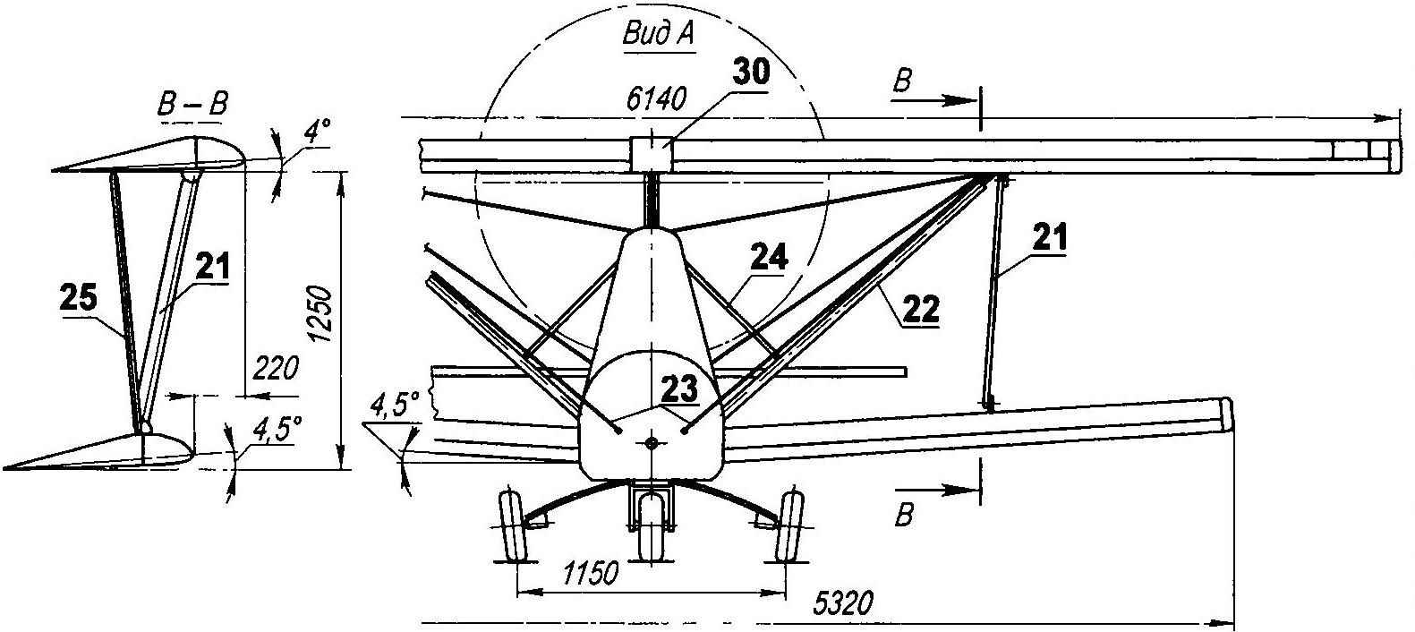
Top polycryl with the installation angle of 4° are mounted on the pylon of a b-pillar V without a transverse Gap between them closed dural patch. In addition, each upper wing is attached to the main beam farm strut and wire brace.
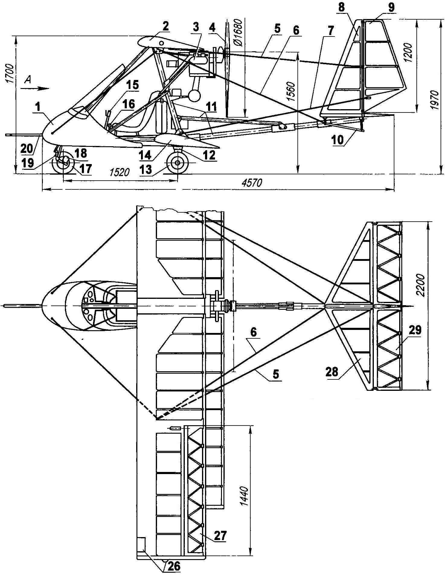
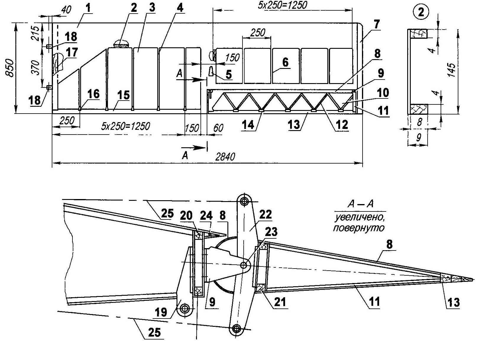
Aeromodel:
1—front wheel (driven, brake, Ø 280, b90, map),
2— front front wheel
3 — fairing (fiberglass),
4, the receiver air pressure,
5 — instrument panel,
6 — handle control of the aircraft,
7 — the windshield;
8 — seat frame,
9— front strut,
10 – brace motor (dural tube Ø 16×1),
11 – pole mounting of the upper wing
12 is a motor frame,
13— engine Rotaх 582, N = 64, l s ,
14 —radiator
15 — the screw shaft
16 — e-block,
17 —muffler,
18 — a Central strut
19—battery,
20— fuel tank V = 20 liters (aluminum canister),
21 — the tail boom,
22 — spring main wheels,
23 — main wheel (Ø 280, b90, from card, 2 PCs),
24—seat,
25 —pristezhnye belts (automotive),
26 — tool kit,
27— lever dvigatelem,
28— brake mechanism.
Lower polycryl dock to the main beam farm cross V = 4,5°. The installation angle of the lower wing is also a 4.5°.
Horizontal tail (GO) consists of the stabilizer and rudder.
Vertical tail (IN) includes the keel and rudder (PH) Handlebar — one-piece with the knife, rejected on the ground of the stabilizer and fin are connected by brackets and struts, and the upper ends of the struts micrylium racks — cable braces.
![The instrument panel and main controls]()
The instrument panel and the main controls:
1 —lever engine control,
2 — the switch of headlights
3 — AZS generator 1,
4—lamp generator failure 2,
5 — light generator failure 1,
6—ignition switch 1-th contour
7 — variometer (pointer speed of ascent and descent),
8 — ignition switch 2-th contour
9—pointer horizontal velocity,
10 — accelerometer,
11 —warning lamp for engine malfunctions,
12 — gauge slide,
13 — integrated control device of engine
14—the altimeter,
15 watch
16 — cigar lighter socket,
17 — fuel gauge,
18 — power switch,
19 — pedals control rudder and nose gear (2 PCs.)
20 — AZS starter
21 — station of generator 2,
22 — rocker switch on beacon and signal lights,
23—stick control of the aircraft,
24—button engine start,
25 — the switch of illumination of devices
26 — brake lever.
The power range of the fin and stabilizer similar to that used in the wings and the rudders and height — as in the flap with a zigzag arrangement of ribs. Profile of all elements of the tail — symmetric TSAGI-683. The leading edge — from millimeter plywood and the spar — plain (percale). The coating is also emalirovka.
Powerplant
First, the aircraft was equipped with two-cylinder engine RMZ-640 capacity of 32 liters. from the snowmobile “Buran” and monoblock two-bladed pusher propeller with a diameter of 1600 mm with a constant pitch. And with this setting the plane for many years good flying and confidently ruled But one day I learned that sold relatively inexpensive two-stroke liquid-cooled engine Rotах 582. It turned out that the motor is disassembled: the owners wanted to renovate, but to collect then failed. So I bought “loose” and then gathered in the course of eliminating faults.
The upper right half-wing (left — mirrored):
1 — upholstery nozzle (plywood s1)
2 — spar,
3 — tight plane (percale soaked Amalita),
4 — rib,
5 — fairing wire rope control Aileron (4 pieces),
6 — partial rib,
7 — ending,
8 — trim the nose of the Aileron (plywood s1)
9 kanipan-Aileron linkage (2 PCs),
10 — slinky Aileron (percale soaked Amalita),
11 — end rib Aileron (root — mirror),
12 — oblique rib of the Aileron,
13— trailing edge Aileron,
14 — cnica Aileron,
15 — the rear edge of the wing,
16 — cnica wing
17 — the root rib,
18 — mount wing bracket pole (2 PCs),
19 — bracket migraleve stand,
20 — “the wall”- extra spar
21—the spar of the Aileron,
22 — rocking control Aileron,
23 — the axis of swing of the Aileron (2),
24 — visor
25 — control wiring Aileron (wire Ø 1,5, 2 PCs.).
The size, weight, and volume of two cylinders Rotах approximately the same as the RMZ-640, but its capacity exceeds almost twice (there is even a version that the second motor is not quite a good copy of the first). Besides Rotах has a dual ignition system (two spark per cylinder) and liquid cooling of the cylinders, the Fuel-deficient — automobile gasoline AI-95 in the mix with the engine oil in the ratio of 50:1.
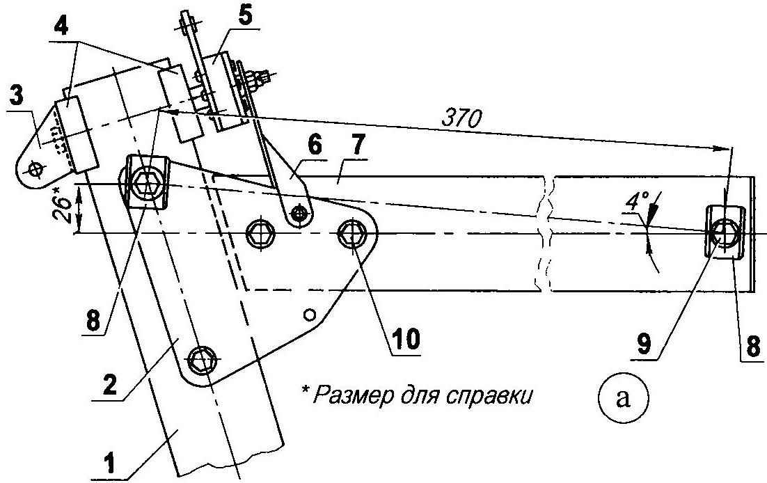
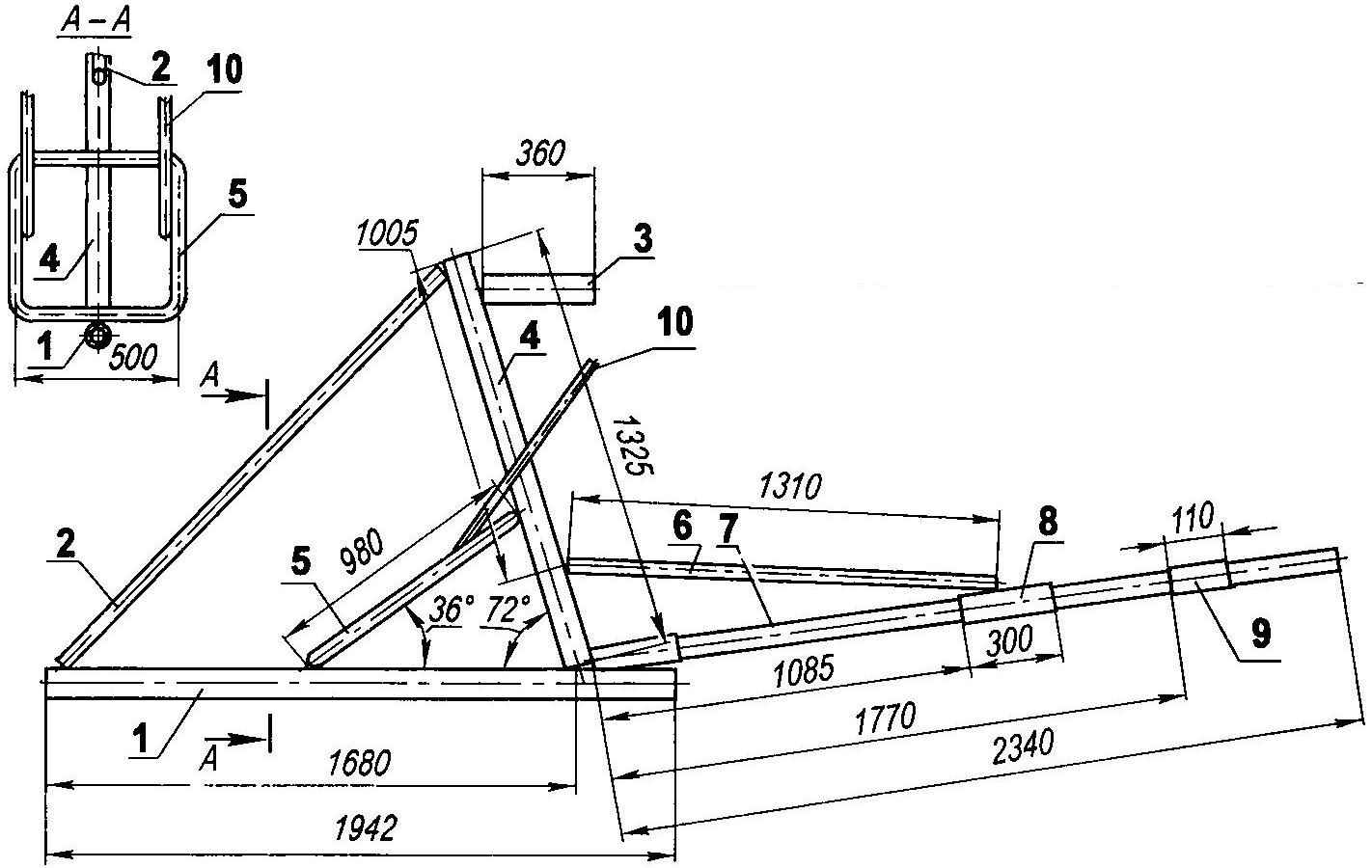
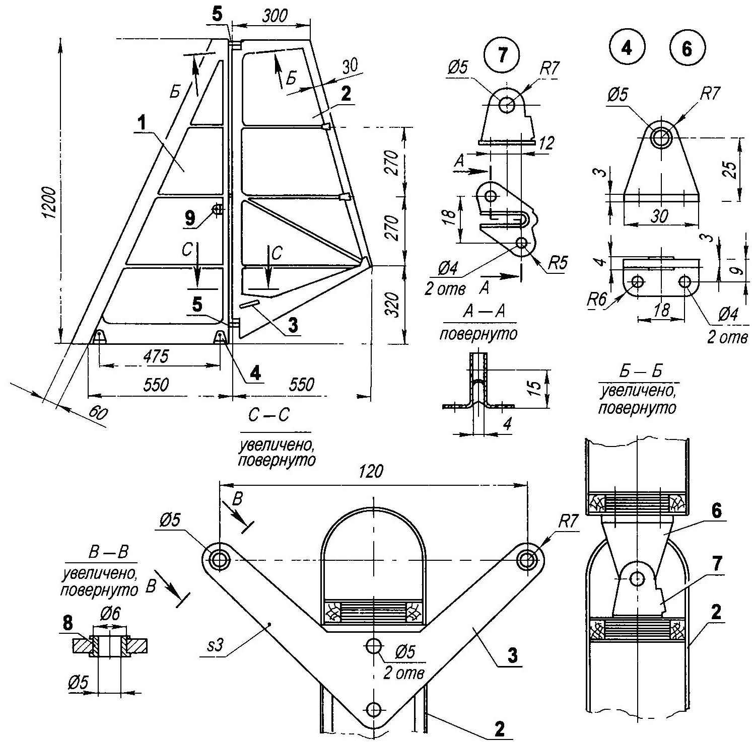
The attachment of the upper wing (Unlisted material details positions — duralumin):
1 —Central stand (tube Ø 60×2),
2 — plate mounting of the pylon to the main stand (sheet s4, 2 PCs.)
3 — a bracket front brace (stainless steel, sheet s2,5),
4 — radius washers,
5 — rocking the ailerons
6— bracket rocking the ailerons
7 — pylon (tube Ø 60×2),
8 — mounting brackets console upper wing (4 PCs)
9 — mounting brackets to the power elements (M12, 2pcs),
10—fixing plates to the power element (bolt M8, 3 PCs.).
And if you replace the engines almost never had to redo the attachment points, the screw had to buy a new one: with a diameter of 1680 mm is also a pusher, but a three-blade, adjustable on the ground step. A reduction gear with a ratio of 3.47 linked with the motor and the screw provides up to 1,900 rpm.
With a new rotor setting the plane purchased and higher performance characteristics, was able to perform fairly complex maneuvers.
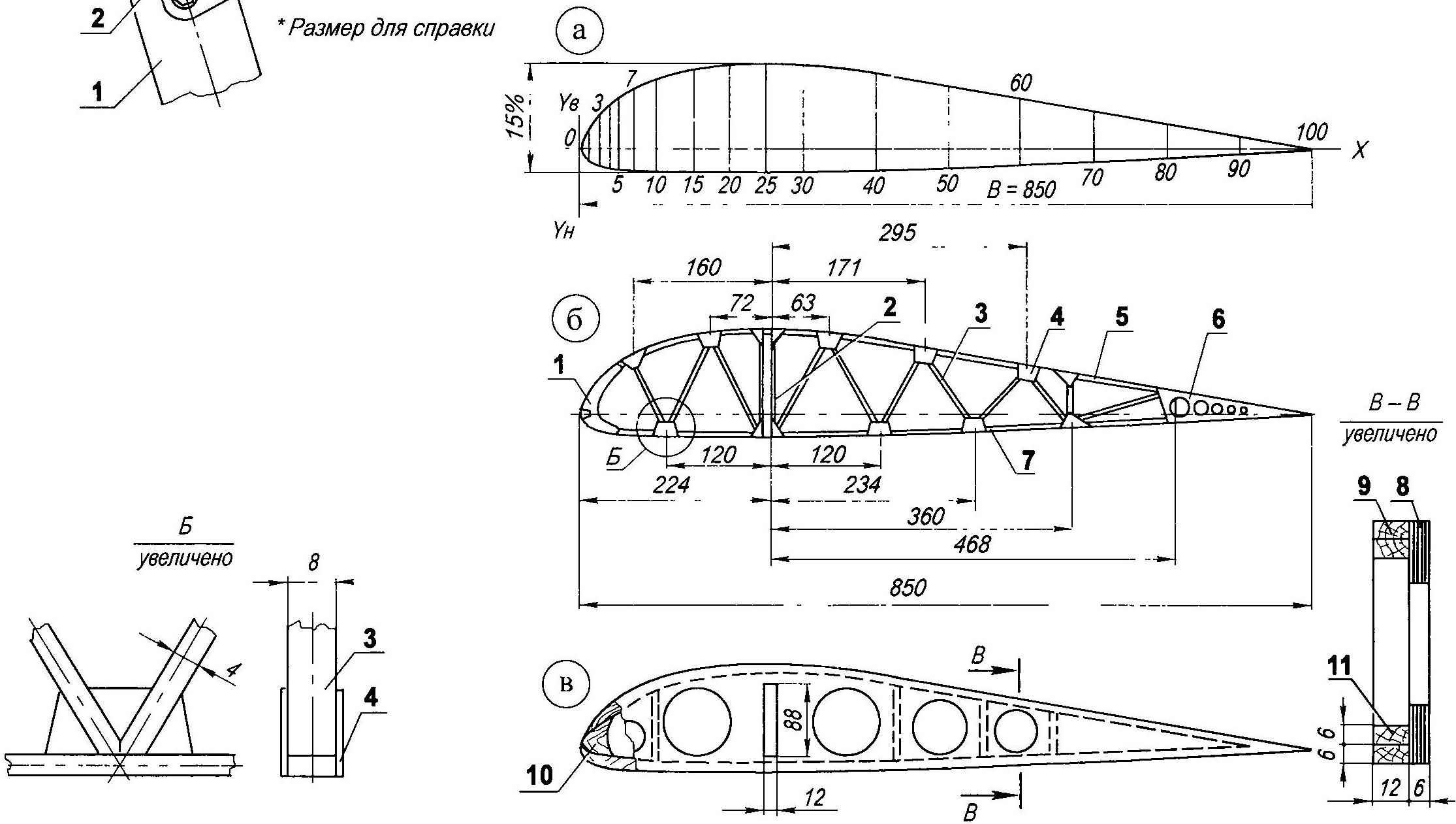

The profile of the wing and ribs (a profile. b— rib, the root rib and ending):
1 nose rib (pine rack of variable cross-section),
2 — front longeron opening (pine rack 8×4, 2 PCs.)
3 — brace (pine rack 8×4),
4 — knize (plywood s1)
5 — top bow rib (pine rack 8×4),
6 — end cnica (plywood s1)
7 — lower the bow (raked pine 8×4),
8 — side panel (plywood s6),
9 — top bow (gluing of the two pine strips 12×6),
10 — the nose of the root rib (pine liner peremennoy section),
11 — lower the bow (gluing of the two pine strips 12×6).
Fuel capacity is small — only 20 L. because the aircraft is designed for training colourtrans flights, but it’s fuel enough hour and a half. Fuel is poured into the aluminum canister mounted on the platform behind the driver’s seat.
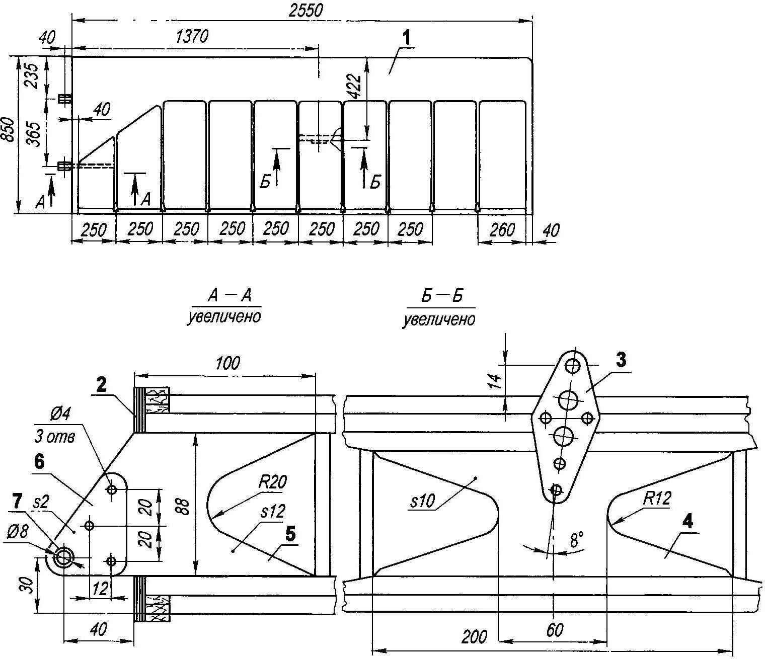
Landing gear — tricycle with front steering wheel. Depreciation is a rubber cord with a diameter of 8 mm, wound noose around the crossbar of the pendulum. The cord ends are connected and fixed to the upper transverse rack.
The lower right wing:
1 sheathing (plywood s1)
2 —root rib (plywood s6),
3 — strut bracket (stainless steel s2),
4 — boss of the bracket (plywood, s10),
5 — lug hub mounting wing (plywood s12, 2 PCs),
6 — panel (aluminum 2, 4 PCs.)
7 — bushing (tube, Ø 8×0,5, 2 PCs.).
Control of the front wheel is the pedals through a flexible (cable) wiring. On the same wheel is mounted and a braking mechanism that is actuated by a lever mounted on the handle control of the aircraft. Rear main support wheels are mounted on a transverse spring made of steel strip.
All wheels are the same outer tyre diameter of 280 mm and a width of 90 mm. they are Used from the map the Track of the rear wheels -1150 mm, and the base (distance between axes of front and rear wheels) is 1520 mm.
![Stabilizer and Elevator]()
Stabilizer and Elevator:
1 — the skin of the nose of the stabilizer (plywood s1)
2 — a close-fitting stabilizer(percale),
3 —covering the spout of the Elevator,
4—tight rudder (percale),
5 — the front part of the rib of the stabilizer (plywood s1)
6—spar of the stabilizer,
7— rib stabilizer,
8 — a wall of a stabilizer,
9 — jointed stabilizer bracket (2 PCs ),
10 — suspension hinge pin of the Elevator (SST),
11—bracket rudder (2 PCs ),
12 — the front part of the ribs of the Elevator,
13 — rib of the Elevator,
14 —the trailing edge of the Elevator.
To protect the tail boom from damage when you touch its land provided the heel.
The aircraft was initially conceived without cabin — only in this case it is possible to fully enjoy the flight and feel the car But later it was equipped with a homemade fiberglass nose fairing with a bottom and a transparent cover 5-mm sheet of Plexiglas.
Keel and rudder:
1 — Kiel,
2 — the rudder
3 — rocking chair (D16, sheet s),
4 — bracket keel to habilitator (4 PCs.)
5 — hinge hinge of the rudder (2 PCs ),
6 — lug hinge hinge of the rudder (aluminum, sheet s, 2 PCs ),
7 — eye of the hinge of the rudder (stainless Shal. sheet s1, 2-piece),
8 — Bush (stainless steel, pipe Ø 6×0,5, 2 PCs),
9— bracket braces (2 PCs ).
The seat is homemade, too. It is based on are nylon straps sewn to the inclined frame, which serves as an additional brace the b-pillar. On the basis of stacked foam cushion and backrest, covered with a thick cloth — avizent. Pristezhnye belts — automotive belts.
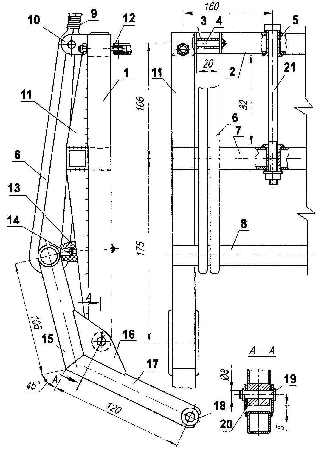
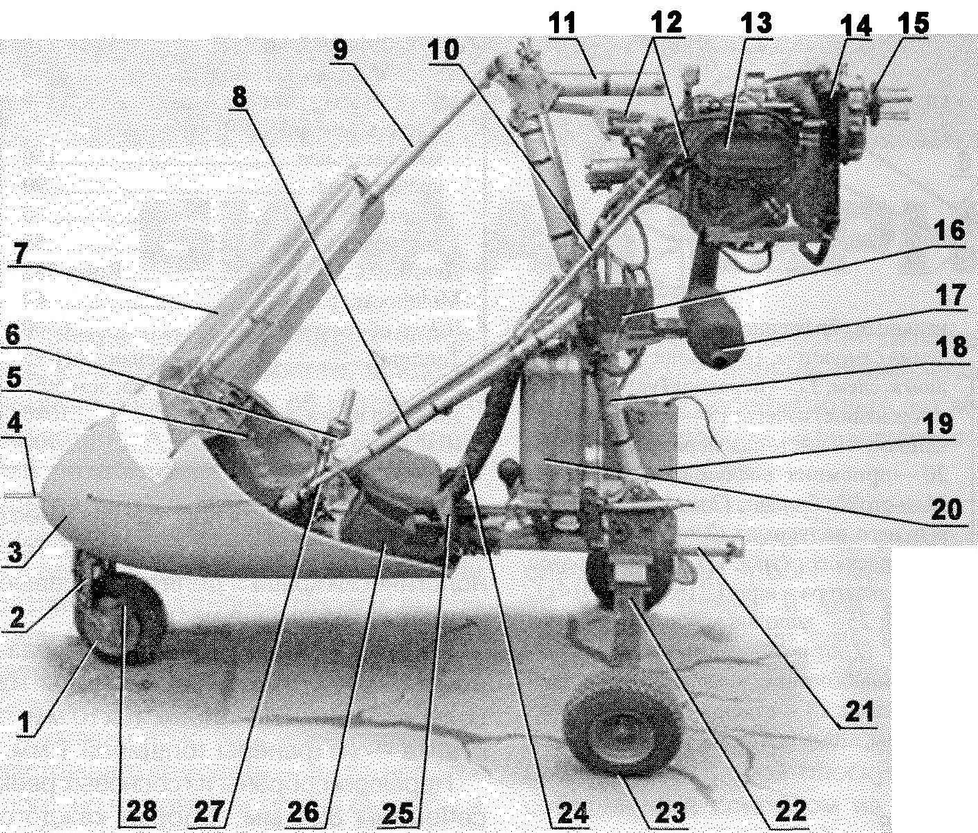
The front landing gear (details of positions I, 2, 7, 11, 15, 17 made of steel tube 20x20x1,5):
1 — front fork,
2 — the upper cross member of the fork,
3 —drum rubber strap (pipe Ø 10×1, 2 PCs),
4 — roller rubber harness (lap 8. 2 PCs ),
5 — Bush-axis of the support pillar (pipe Ø 12×2, 2 PCs ),
6 — shock absorber (rubber cord Ø 8, 4 PCs ),
7, the lower cross member plug,
8 — crossbar duplicera lever (pipe Ø 20×2),
9 — belt (nylon thread),
10 — lug axle (steel sheet s2, 4 units ),
11 — strengthening struts (2 PCs),
12 — bolt-eyelet fastening control wiring (2 PCs),
13 — emphasis (rubber 2pcs),
14 — mount the stop (bolt M4, 2pcs ),
15 — top knee duplicera lever (2 PCs),
16 — Klondike (steel sheet s2, 4 units ),
17 — lower knee duplicera lever (2 PCs),
18 the hub of the wheel axle (2 PCs),
19 — axis duplacey lever (roller Ø 8 with washer and cotter pin, 2 sets),
20 — Bush axis duplacey lever (2 PCs ),
21 — the rack axis.
Control system aircraft cable with intermediate rods from the control stick (RUS), located on the farm before the pilot engine Control lever set to the left of the pilot. The deviation of the rudder and rotation of the front wheel on the taxiway, pedals. The aircraft is equipped with necessary devices, providing flight in simple meteorological conditions (IMC), which controls the operation of the engine they are All located on the dashboard in front of the pilot. On the upper wing there are lights, and the tail is still and navigation lights with regard to flight characteristics of the aircraft, some of them are given in the table, while others, such as the rate of climb, maximum altitude, still was not measured.
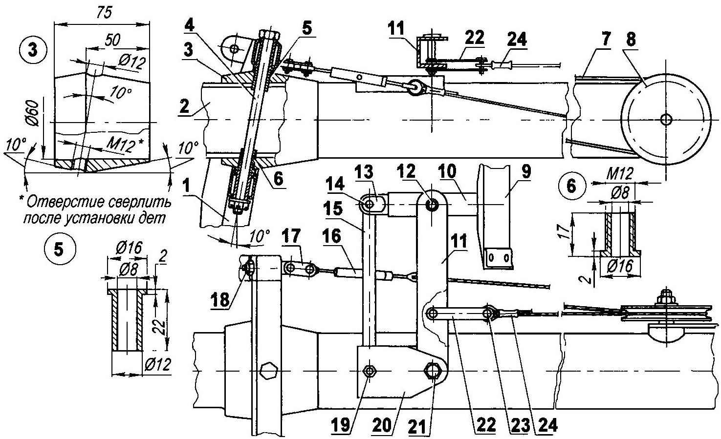
Control of the front landing gear:
1 — front,
2 — main beam,
3 — bougie (D16T, pipe Ø80×10),
4 — axis stands (M10 bolt with castellated nut and washer),
5— upper bearing bushing (bronze),
6 — bottom bearing bushing (bronze),
7 – cable Ø 1,8,
8—Racic,
9 pedal,
10 — lever
11— rocking chair
12 — the axis of the lever and rocking
13 —the tip of the lever,
14—the axis of the tip of the lever and thrust
15 — rod
16 — thunder,
17 — earring racks,
18— bolt-lug,
19—axle traction
20— bracket thrust and rocking
21 — the axis of rocking
22—earring rocking
23 — roller with cotter pin (4 sets),
24 — termination of the cable.
A considerable advantage of this design is that it is collapsible. For transporting (or storing) the aircraft can be disassembled into several parts: from euromodule disconnected polyrinia, tail boom, and from her tail. The tail unit is carried on the roof the trunk of the car, and the remaining part in two-wheeled trailer for automobiles, mounted on a special platform. Stored along with the trailer in a regular car garage and is collected in the field in less than an hour by one person.
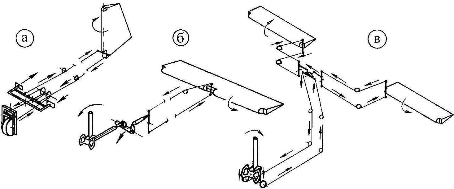
Control scheme of the plane (and the rudder of the b — Elevator, to —Aileron).
From the editor. The editorial warns that the flights on homemade LA permitted only with the appropriate certificate and pilot’s certificate.
Recommend to read
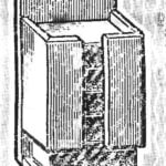 MATCHBOX “ELEVATOR”
Matches... How many times we use them for the day! To do this, constantly having to open and close the drawer or get them off the shelf — they are thrown on the table — the baby was right...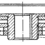 “ETERNAL” BRUSH
In various treatment machines, cleaning the role of the washcloths make circular nylon brush. But making nylon circles and repairs them after wear synthetic bristles — a difficult and...
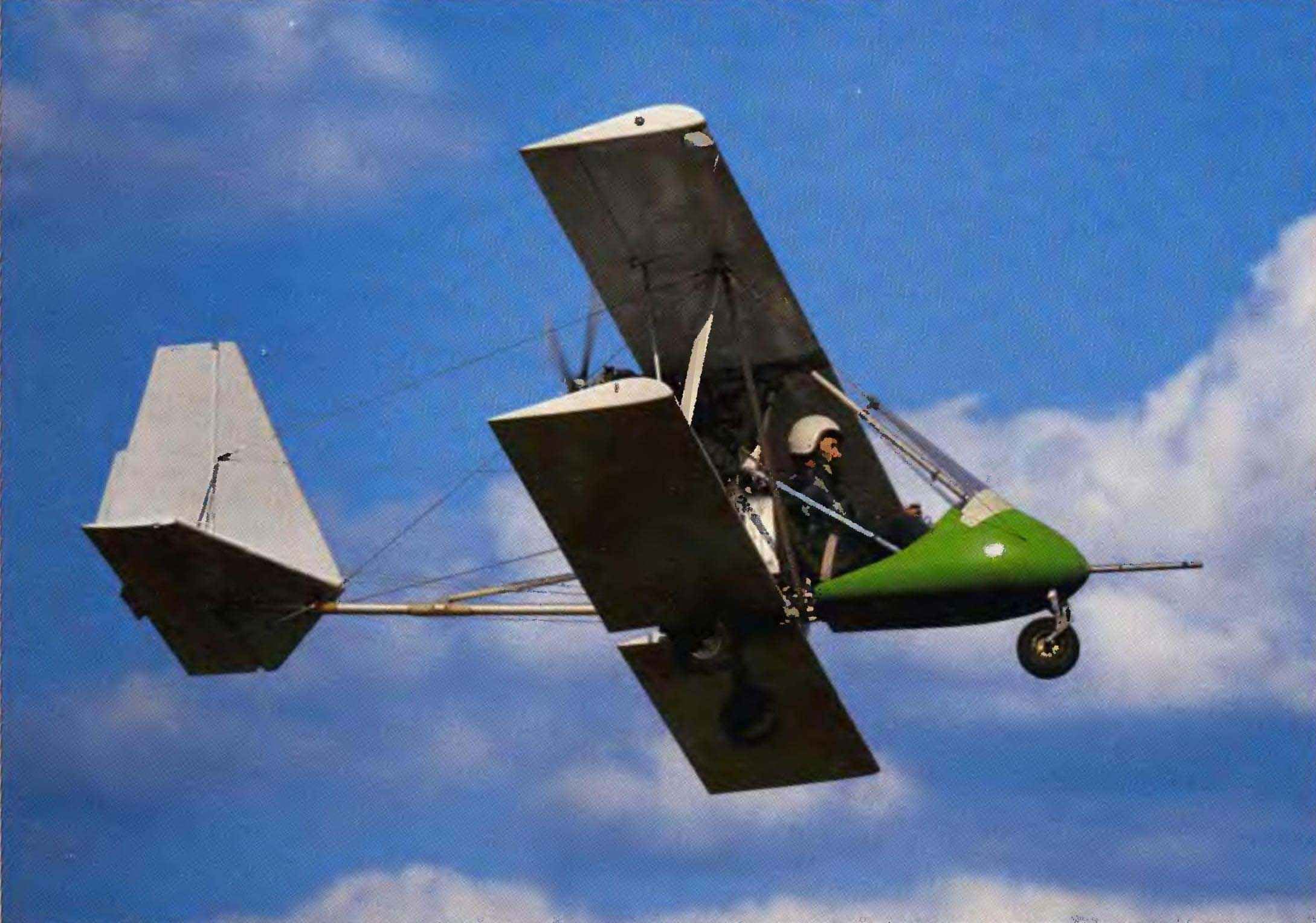
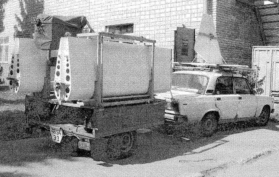
 Last summer, the head asiacruise Vnukovo house of culture (Moscow) Amateur pilot, Andrey Chernikov demonstrated are designed and built with his own hands a single biplane rather complicated maneuvers over the airfield Expanse in the Vladimir region.
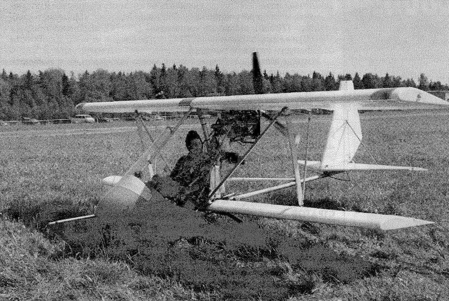
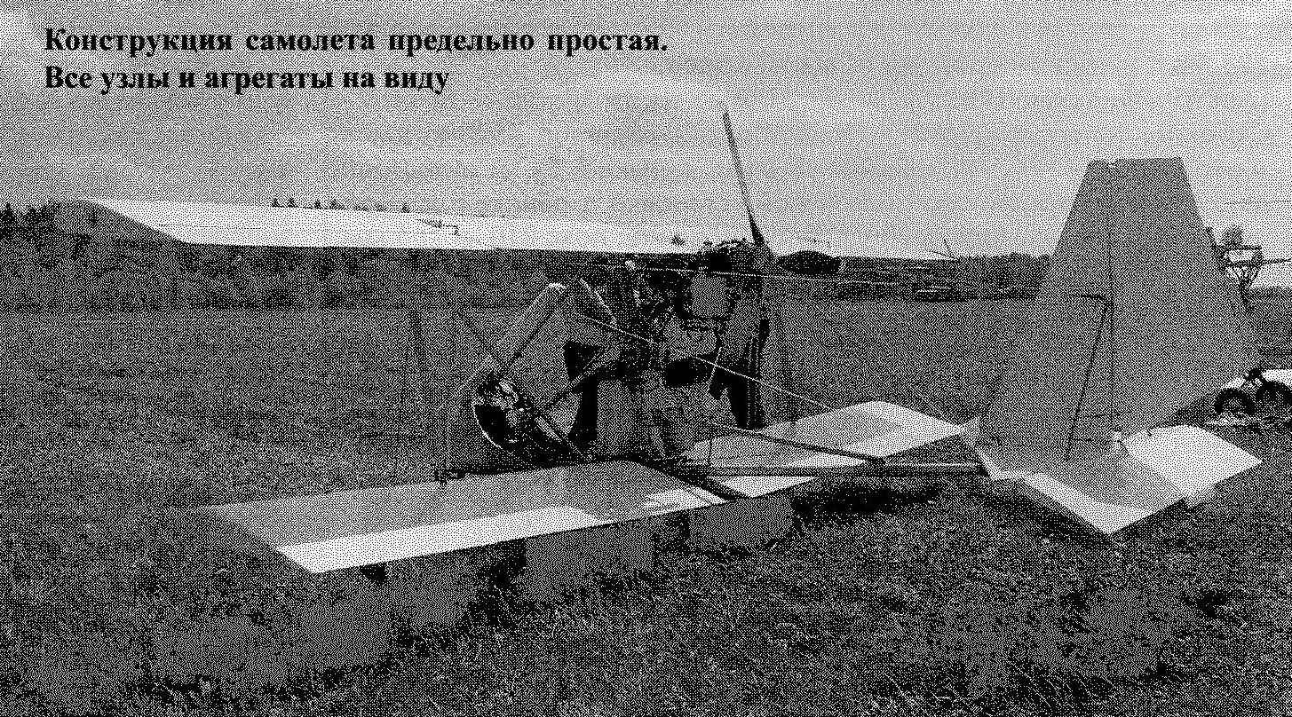 Military aircraft design is a flat farm, collected mostly from duralumin tubes with a diameter of 60 mm with a wall thickness of 2 mm. To this farm is attached wings, empennage, powerplant, fuel tank, dashboard, chassis, seat and fairing of the pilot. Pipe farm are connected through plate plates including notched curved washers, bolts and self-locking nuts.