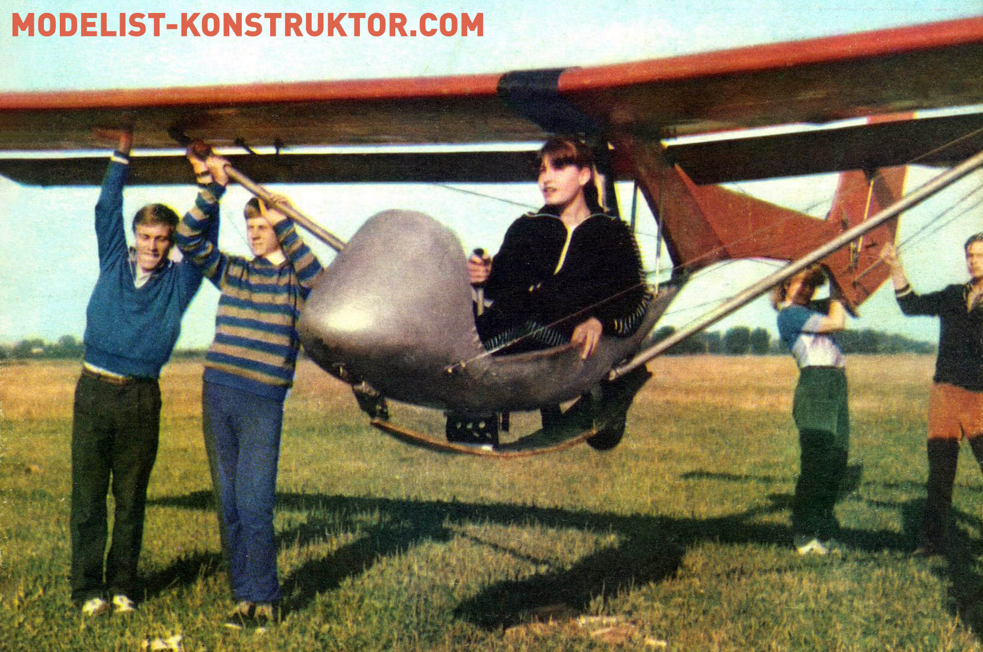
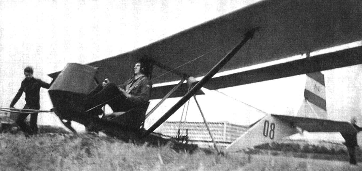
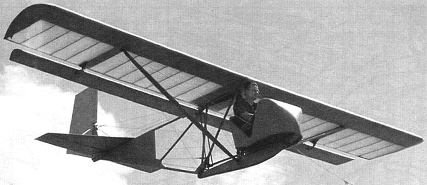
Did you know that many amateur-built aircraft have the BRO-11M glider as their basis – the initial training glider from the well-known Lithuanian aircraft designer B.I. Oshkinis? Quite simple to manufacture and reliable in operation, designed based on the principles of the classical school of aircraft design of the 1930s, the glider won the favor not only of novice glider pilots but also of amateur aviators who saw in the design of both the BRO-11M itself and its individual elements a lot of useful information for creating amateur gliders and airplanes. Some used the glider scheme as a whole, others copied the wing structure, and still others – its original control system… In short, the BRO-11M became a kind of tutorial for aspiring aviators.
So, Bro-11M is an inclined high-wing glider with a monolithic wooden structure and a truss fuselage.
WING AND AILERONS
The glider’s wing has a very simple and typical structure for gliders of the 1930s, which can be taken as a basis for independent design and construction of similar purpose aircraft. This is confirmed not only by the work of B.I. Oshkinis himself, who created several initial training gliders with such a wing, but also by the developments of many amateur aviators who built gliders, motor gliders, and airplanes following the example and likeness of the BRO-11M.
Of course, in each specific case, strength standards should be taken into account – the wing discussed here is designed only for use on the BRO-11M; in the case of its installation, for example, on a light aircraft, the wing must be recalculated for strength and, if necessary, its main elements reinforced.
The BRO-11M wing consists of two symmetrical half-wings of a monolithic wooden structure, which are attached to the fuselage truss at the root of the spar and rear stringer. Each half-wing is fixed with a strut, the upper end of which is attached to the middle part of the spar, and the lower end is attached to the fuselage truss.
Each half-wing set includes a box spar, 17 ribs, front and rear stringers of the trailing edge, plywood skin, caps, and tips. Some metal nodes are installed on the wing frame before assembly (on the spar and ribs), and the rest are mounted on the assembled frame.
The tail boom lock and the rear wing node are mounted on the rear stringer after assembling the wing using two M6x32 bolts and nuts. The attachment point is reinforced with plywood overlays and an ash plank with a cross-section of 34×8 mm.
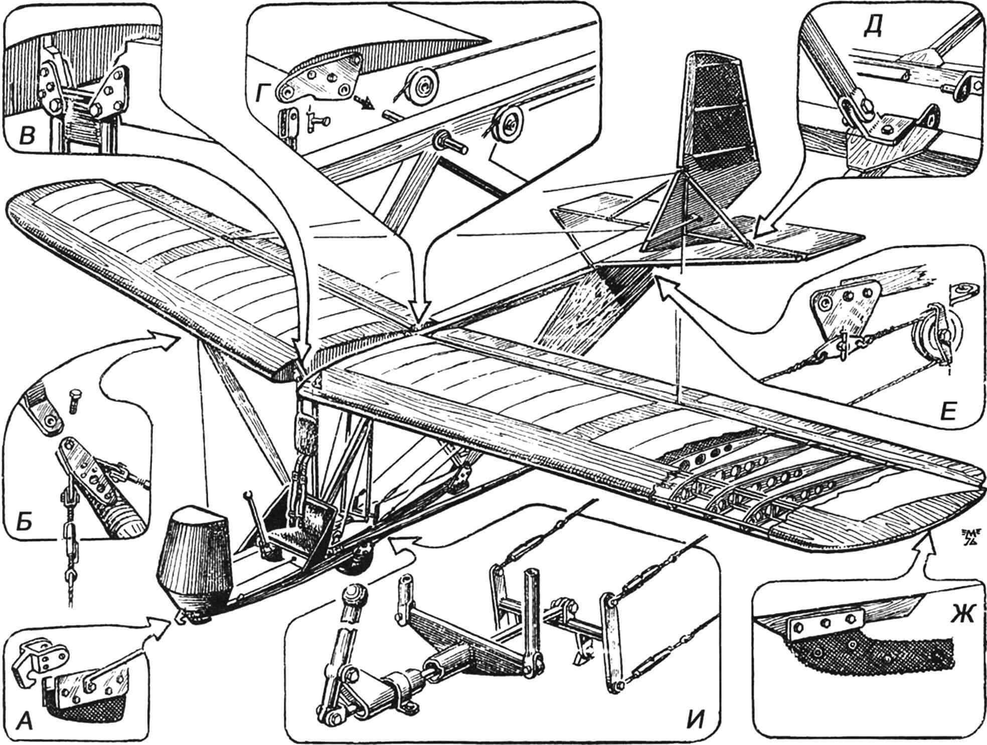
A – towing hook and front rubber stopper, attached to the fuselage truss with M8 bolts; B – upper node of strut attachment to the wing and brackets for attaching tensioners; C – junction node of wing spars and vertical strut of the truss (M8 bolts, overlays – made of 4mm sheet duralumin; D – aileron suspension and installation of rollers for routing control cables of the elevator; E – lower ear of the strut for the stabilizer and installation of the elevator; F – turning roller for routing the elevator control cable and installation of the elevator; G – safety stop on the wing console made of reinforced rubber, 15mm thick; H – a mechanism for controlling ailerons (using two vertical tubular rods) and elevators (using double-armed rockers and cables)
The strut lock is reinforced with three steel pistons with a diameter of 4-6 mm. The folding hook of the lock is pivotally fixed with an M6 bolt, trimmed and installed between two washers. The lock is secured with a roller, at the lower end of which a fixing pin is installed, bent from 1 mm diameter OVS wire.
The wing spar consists of two solid pine slats with a cross-section of 20×10 mm, reinforced with glued strips with a cross-section of 10×10 mm, as well as three caps, fourteen struts, and two end strips. After assembly, the spar is carefully processed with a planer and covered on both sides with 1 mm plywood. The root part of the spar at the fuselage attachment point is reinforced with overlays made of 1 mm plywood, measuring 65×24 mm. The node consists of two 1.5 mm plates of D16T aluminum, pulled together by pistons from a tube of grade 20A with a diameter of 8-10 mm. In the middle part of the spar, reinforced with rails with a cross-section of 12×5 mm and a length of 135 mm, glued to both slats, and overlays made of 1 mm plywood measuring 135×54 mm. In the same place, between ribs No. 9 and No. 10, a strut attachment node is installed, which is welded from a steel plate, two cheeks, and a bushing.
The junction and strut nodes are fixed with M5x21 bolts with washers and crown nuts. The roller is designed to connect the wing to the fuselage.
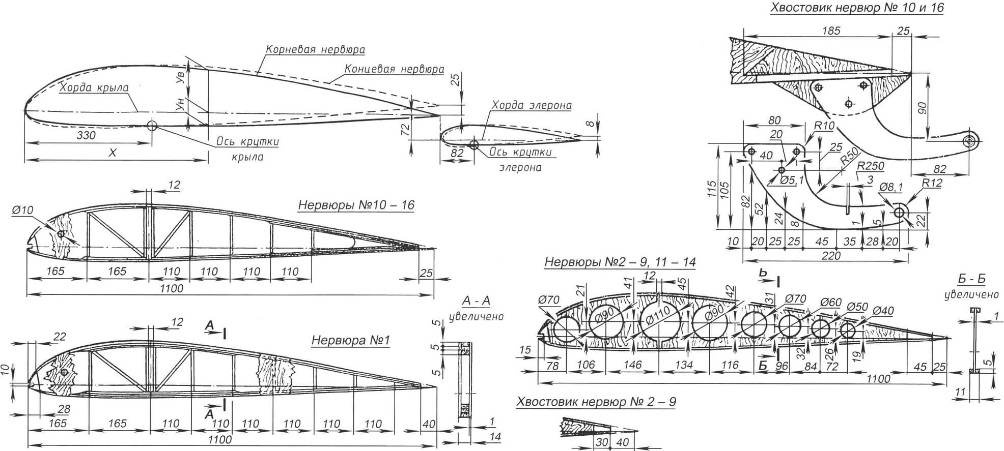
Profiles of the wing and aileron are shown in the table of control sections (both have a positive twist of about 2 degrees, increasing the wing efficiency at large angles of attack; flow separation occurs first in the middle part of the wing). The required twist is achieved by a slight bend of the spar in the stack before covering the front part of the wing with plywood – after this operation, the wing will maintain the required twist.
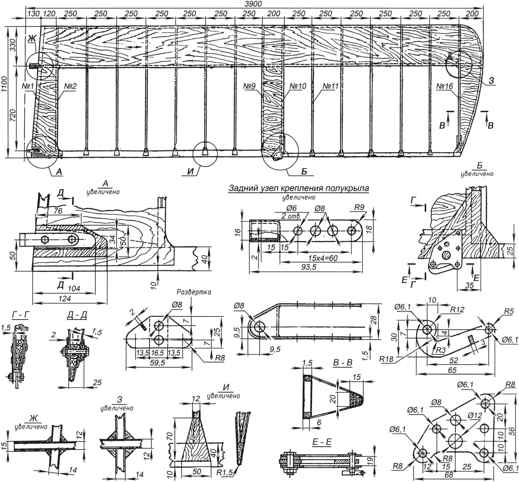
All ribs have the same profile and chord but differ in design. For example, ribs No. 2 – No. 9 and No. 11 – No. 14 have a double-T section, assembled with glue and nails from four strips with a cross-section of 5×5 mm, two caps, and a wall made of 1 mm plywood with holes for weight reduction.
The root rib has a reinforced box section. Its slats are glued from strips with a cross-section of 12×5 mm. The struts adjacent to the holes for the spars have a cross-section of 12×10 mm, and the remaining struts and braces are 12×5 mm. Ventilation holes are cut in the walls of the front part of the rib for ventilation. Reinforced ribs No. 10 and No. 15 are similar in design to rib No. 1 and have the same cross-sections of strips.
At the bottom of rib No. 10, a cap measuring 185x52x14 mm is glued. The tail boom and cap are covered on both sides with 1.5 mm plywood measuring 210×94 mm, on top of which two strips with a cross-section of 10×8 mm and a length of 185 mm are glued. Three M5 bolts attach the bracket for suspending the aileron to the cap, cut from a 3 mm sheet of D16T aluminum with a thickness of 3 mm. A steel bushing with a diameter of 8×1 mm is inserted and rolled into the bracket hole. The tail boom of rib No. 16 has a similar construction, only the cap is intended to protect the wingtip from hitting the ground.
The ailerons are suspended under the wing on two hinges, one of which is located on the fuselage truss, and the other is on the rib No. 10 bracket. Unusually large wingspan of the suspended ailerons, almost equal to the wingspan, provides their high efficiency.
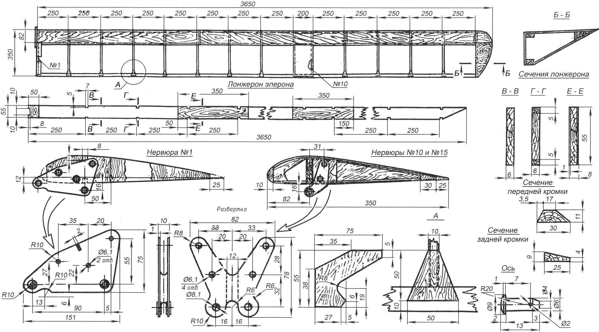
The aileron frame consists of a spar, sixteen identical ribs, front and rear stringers, as well as coverings and knits. The ribs in the set are positioned at the same distances from the glider’s symmetry plane as the wing ribs.
Each spar consists of a pine plank with a cross-section of 55×8 mm with three double-sided reinforcing overlays. The reinforced aileron rib No. 1 consists of a pine strip with a cross-section of 55×6 mm and a length of 315 mm, covered with 1 mm plywood: on the outer side – along the entire length, on the inner side – for 122 mm from the nose of the rib.
The reinforced rib No. 10 is assembled from two slats with a cross-section of 7×5 mm, two knits in the nose with a cap between them, plywood wall, a small knit at the end, as well as a cap and knits in the middle of the rib for attaching the aileron hinge. The structure of normal ribs is the same as rib No. 10, except that the middle cap with knit is absent.
The aileron tip with the root hinge ear is made of 2 mm sheet duralumin. Steel pipe bushings with a diameter of 8.1 mm are rolled into the lower holes. The tip is attached to the outer side of rib No. 1 with three M6 bolts, 20 mm long. The aileron bracket on rib No. 10 is also secured with two bolts of the same type.
WING BRACES
The wing braces are made from pine blanks, each of which is glued with epoxy resin from two planks with a cross-section of 85×20 mm to avoid warping. The planks should be straight, without knots, rot, and slope. After gluing, the blank is processed using templates according to the brace sections shown in its drawing.
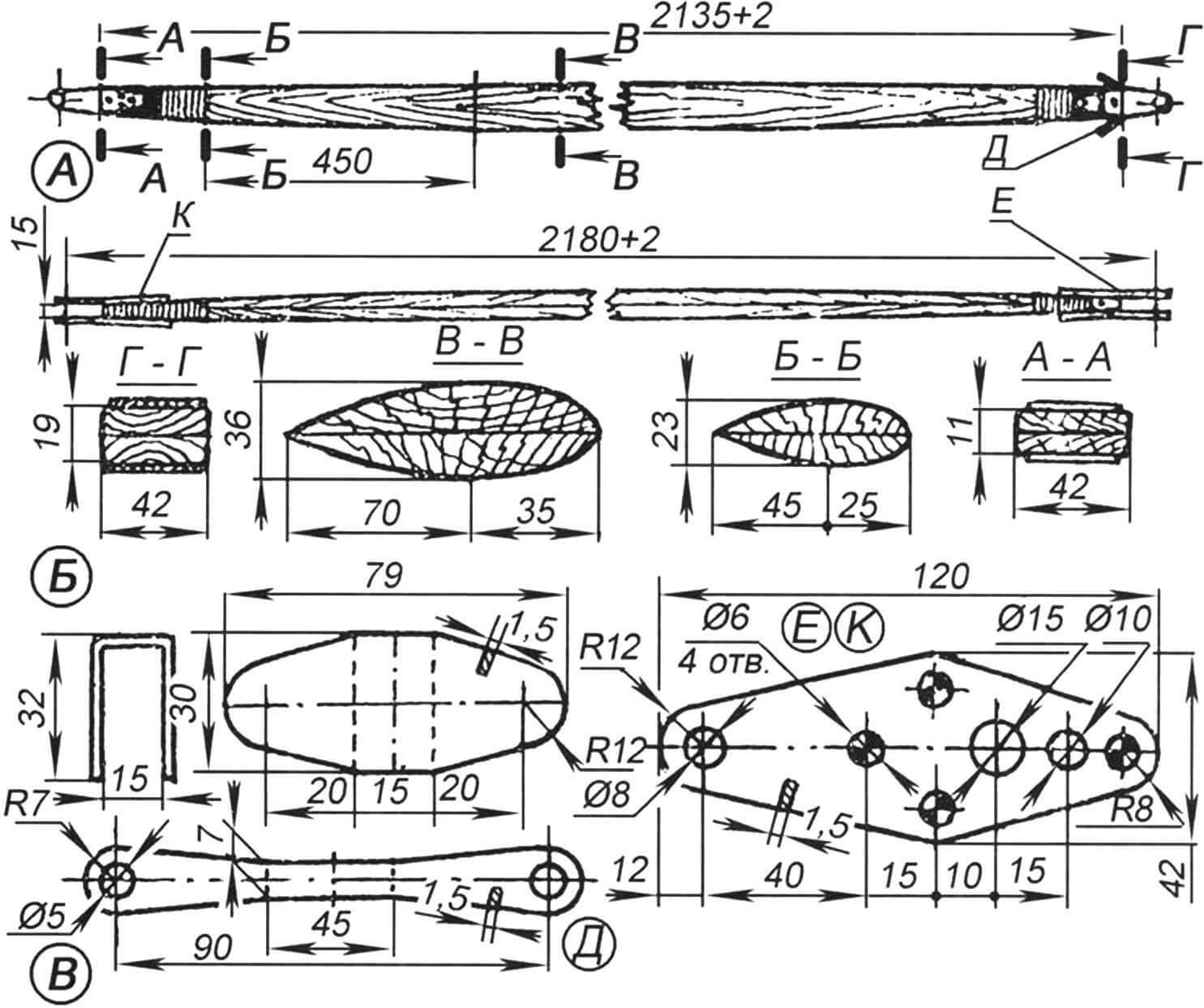
A – main dimensions of the brace; B – brace sections; C – brace details (material – St.20)
The end parts of the braces are pyramidal in shape. After covering these areas with fiberglass using epoxy resin, the upper and lower tips are attached by welding from sheet steel St. 20, and are fastened to the brace with M6 threaded bolts. The upper brace tip is secured with M8 bolts and crown nuts on a bracket installed on the wing spar near rib No. 10, and the lower one is attached to the front strut node of the fuselage truss. After mounting, the crown nuts are securely pinned.
From the upper brace tip, cable bracing extends to the front part of the fuselage truss and tail assembly.
The ends of the cables are spliced on thimbles or secured with copper tubing. The necessary tension of the bracing is achieved by turnbuckles with a length of 100 – 150 mm with a thread of at least M5. The turnbuckles are secured with soft steel wire with a diameter of 1 mm.
TAIL ASSEMBLY
The tail assembly consists of fixed elements (keel and stabilizer) and movable ones (rudder and elevators). The keel is connected to the stabilizer by a pair of tubular struts, the ends of which are finished with P-shaped brackets.
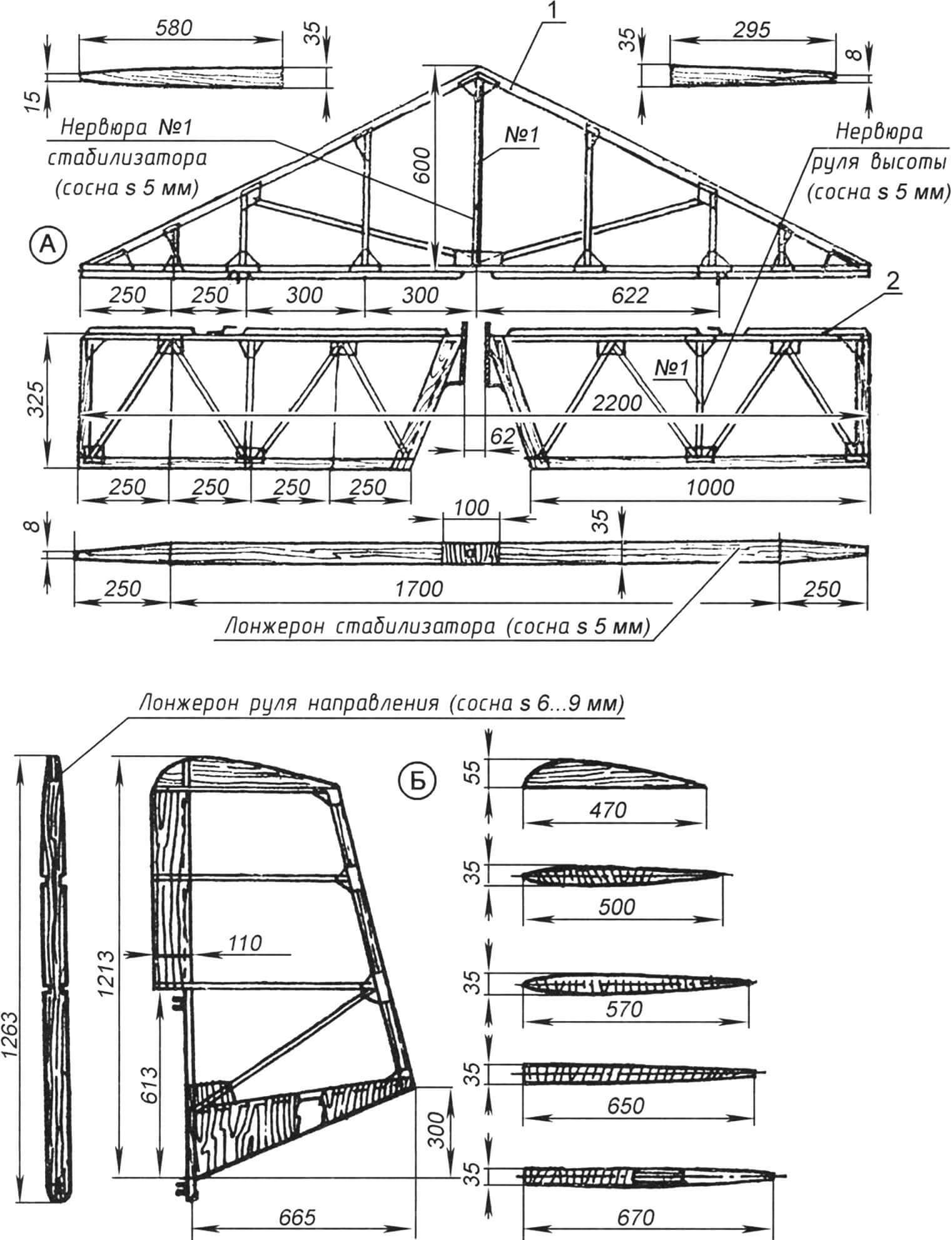
A – horizontal assembly:
1 – stabilizer; 2 – elevator;
B – rudder
The stabilizer has a triangular shape in plan. Its frame is assembled from a spar, seven ribs, a front edge, four knits, and 32 stringers. The spar is made from a pine strip with a cross-section of 35×5 mm with a plywood overlay (reinforcer) in its middle part. Four strips with a cross-section of 10×7 mm are glued to the rear wall of the spar. Reinforcing the spar, they also serve to reduce the width of the gap between the stabilizer and the elevators. Ribs No. 1 (central) and No. 5 (diagonal) are made of pine strips. The node used for attaching the brace and suspending the elevators is made of 2 mm sheet duralumin D16T.
The rudder (as well as the elevator blades) has a wooden frame with canvas covering. These glider elements are assembled almost the same way as the wing and ailerons. When covering the rudders with aerolacquer, it is recommended to clamp them with clamps on a thick board to prevent warping.
COVERING OF THE WING AND AILERONS
Covering the wing and aileron frame with fabric is a very responsible operation, the success of which depends on the overall aerodynamics of the glider. Preparation for this operation involves carefully filing and sanding the surfaces of all frame parts that will come into contact with the fabric.
The best material for covering is aviation percale, but it is not easy to find it now. However, you can cover the glider with satin or calico. It is advisable to cover the glider with one piece of fabric or make a blank with a minimum number of seams.
After preparing the fabric in this way, it is applied to the frame pre-coated with glue. It is advisable to use nitro glue AK-20 or aerolacquer for the first coating. Care should be taken to ensure that the fabric is well pressed against all elements of the frame and evenly stretched. It is particularly important to ensure a tight fit to the plywood skin of the wing’s leading edge.
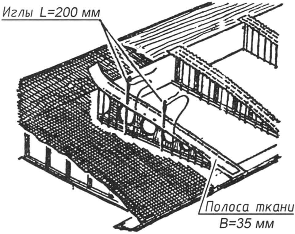
Once the glue is dry, the covering is stitched through the ribs with “moke” type threads (modern Lavalan thread can also be suitable) using a special long needle. After that, the seams are covered with kipper tape – strips of fabric with serrated edges. This operation is necessary to prevent the fabric from peeling off the frame during glider operation.
Further surface treatment involves covering them with aerolacquer for even and strong stretching of the fabric and to make it waterproof. The wing is coated with enamel in two to three layers with interlayer drying and fine sanding to eliminate minor irregularities and dust. Apply the lacquer with a spray gun (or, in extreme cases, with a wide soft brush without pressing on the fabric). The final painting of the wing is done with nitro paint with high coverage, in two to three layers. The last coating is clear nitro varnish with subsequent polishing using automotive “polish.”
FUSELAGE
Applied to the BRO-11M, this name is purely conditional because this aircraft does not have a fuselage as such. Instead, the glider has a flat power truss made of pine beams, to which the gondola with landing gear (250×125 mm chassis wheel and shock-absorbing skis), the pilot’s seat with a semi-fairing, wing consoles with ailerons on both sides of the truss, and the tail assembly at the rear are attached. The joining of all these elements is well thought out and allows for quick assembly and disassembly of the glider.
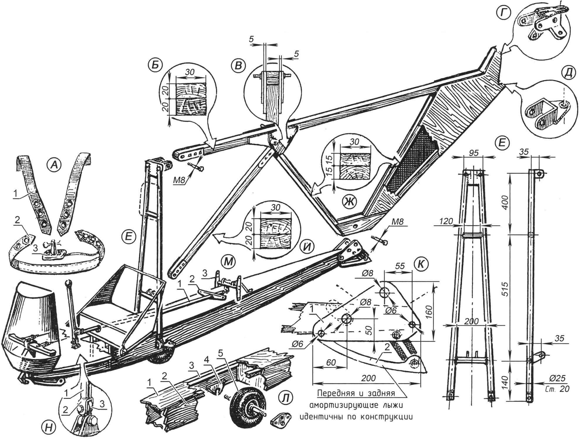
A – safety belts: 1 – shoulder straps; 2 – lap belts; 3 – lock; B – longitudinal beam of the truss (glued from pine beams with a cross-section of 20×30); C – junction node using reinforcing plywood knits; D – upper node of the rudder attachment; E – lower node of the rudder attachment (steel, sheet thickness 1.5); E – main strut; G – cross-section of the rear struts of the truss; H – cross-section of the front strut of the truss; K – junction node: 1 – cheek for attaching the tail truss of the fuselage; 2 – shock-absorbing ski; L – mounting of the chassis wheel: 1 – upper panel of the gondola (plywood thickness 3); 2 – variable thickness side wall of the gondola (plywood thickness 20 under the wheel brackets, thickness gradually decreases to 15 towards the nose and stern); 3 – gondola spar (pine, 20×20 strip); 4 – bracket (steel, sheet thickness 5); 5 – chassis wheel 250×25; M – control stick node: 1 – aileron and elevator control rod; 2 – aileron control rocker; 3 – elevator control rocker; N – lower node of the control stick: 1 – pipe 20×2.5; 2 – fork; 3 – dry joint of the universal joint
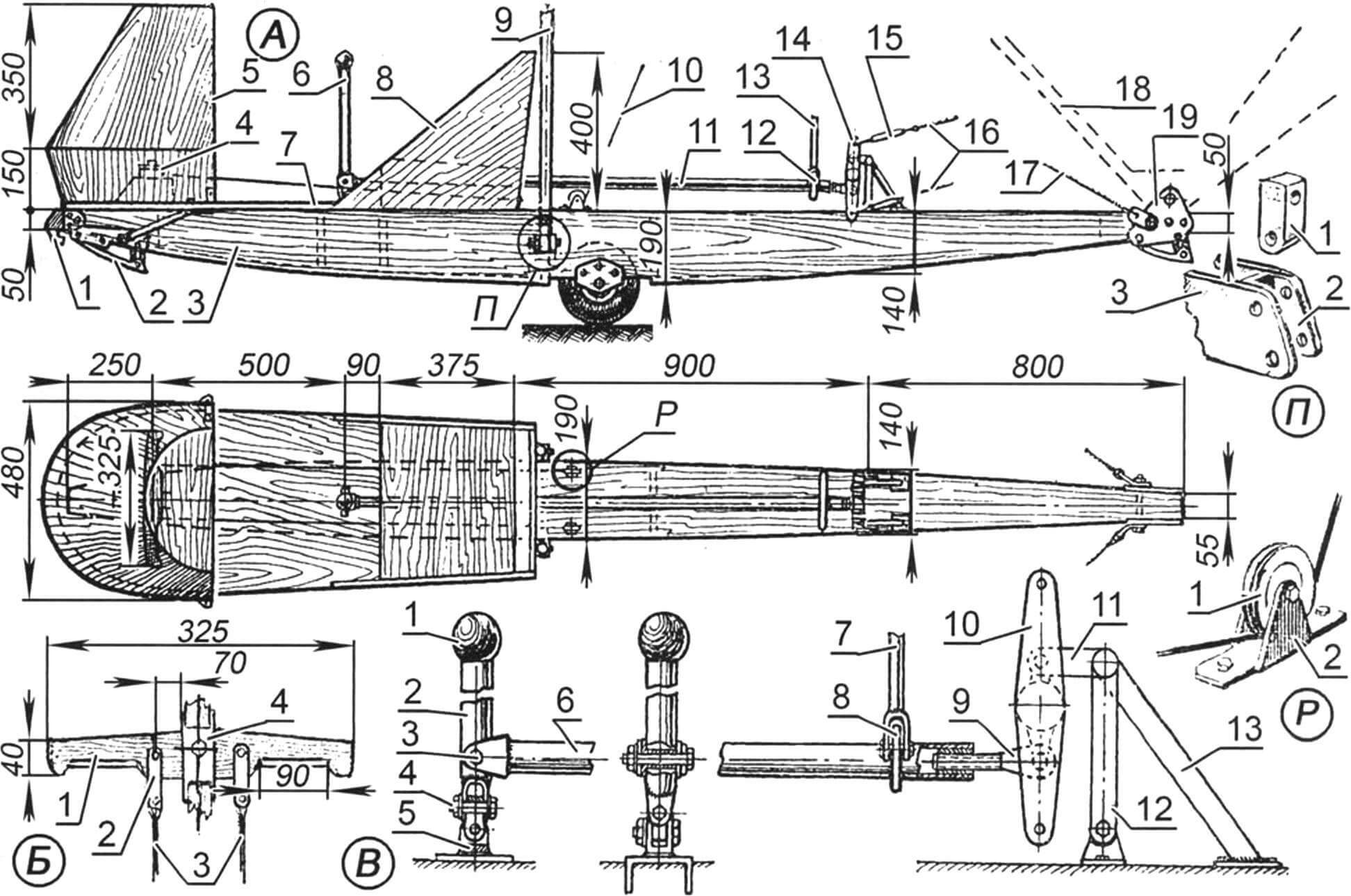
A – BRO-11M glider fuselage gondola:
1 – towing hook; 2 – shock-absorbing ski; 3 – gondola box; 4 – rudder control pedals; 5 – semi-fairing; 6 – aileron and elevator control handle; 7 – cabin floor; 8 – pilot’s seat; 9 – main truss strut of the fuselage; 10 – control cables for rudder control; 11 – aileron and elevator control rod; 12 – aileron control rocker; 13 – aileron control rod; 14 – block of control rockers for elevator control; 15 – turnbuckles of elevator control cables; 16 – elevator control cables; 17 – lower tail brace; 18 – contour of the fuselage truss; 19 – junction node of the truss and gondola
B – Rudder control pedals:
1 – pedals (ash, board thickness 25); 2 – earring (steel, sheet thickness 1.5); 3 – rudder control cables; 4 – bracket for attaching pedals to the base knuckle
C – Aileron and elevator control handle:
1 – handle head; 2 – handle (steel tube 20×2.5); 3 – axis of the fork of the steering rod (M6 threaded bolt); 4 – axis of the cap (M6 threaded bolt); 5 – lower fork; 6 – steering rod; 7 – aileron control rod; 8 – aileron control rocker; 9 – threaded tail of the steering rod connecting it to the block of control rockers for elevator control; 10 – rocker; 11 – bracket for attaching rockers; 12 – strut; 13 – brace (steel tube diameter 12×1)
D – Node for attaching the central strut and brace to the side wall of the gondola:
1 – cap; 2 – bracket (steel, sheet thickness 5); 3 – pad and nuts installed in the gondola box
E – Node for attaching the roller of the rudder control cable to the gondola
The gondola is a streamlined box frame made of pine beams with a variable thickness plywood skin. In the middle part of the gondola is a niche for the chassis wheel. In the front part, there is a towing hook and a shock-absorbing device consisting of a metal ski spring-loaded with a ring made of dense rubber. A similar ski is also installed in the rear part of the gondola.
CENTRAL STRUT OF THE FUSELAGE TRUSS
The central strut of the fuselage truss is welded from steel tubes with a diameter of 25 mm, made of St.20 steel. The upper crossbar of the strut is made of 5-mm steel strip, welded with a tight continuous seam to the tubes of the strut and the bracket for attaching the truss.
TAIL TRUSS
The tail truss is glued with epoxy glue from pine slats with a cross-section of 30×15 mm and 30×20 mm. The rear (triangular) part of the truss is covered on both sides with 1-mm plywood, forming a larger keel surface, which significantly reduces the size of the actual keel. On the BRO-11M, the keel is practically only used for attaching the rudder. Reinforcing bobbins covered on both sides with 5-mm plywood are installed in the lower and upper intermediate nodes of the truss.
The front node of the truss is connected to the bracket of the vertical strut with an M8 bolt, and the lower node is connected to the back end of the gondola with the same bolt and cheeks. The upper intermediate node carries the bracket for hanging the aileron and the pulleys for the rudder control cables. The upper node of the keel serves to attach the upper hinge of the rudder, tail braces, and fork ends of the stabilizer struts. The latter are bent from 1.5-mm steel sheet (blank dimensions – 114×70 mm). Bushings made of steel pipe with a diameter of 8×1 mm are rolled into the holes of the hinge brackets and the stabilizer struts. The lower hinge of the rudder is bent from a steel plate with dimensions of 84×45 mm, and a bushing from a pipe with a diameter of 8×1 mm is also rolled into its bracket.
The pilot’s seat is installed in the front part of the gondola; it is covered from the front with a lightweight semi-fairing made of 1.5-mm plywood, attached to the frame of two hoops. The semi-fairing itself is glued and screwed to the gondola base; at the rear edge, it is additionally fixed with a pair of 3 mm thick aluminum angles.
The pilot’s seat and backrest are made entirely of 4-mm plywood; the seat is attached to the gondola base with glue and screws. The seat and headrest are covered with foam and upholstered in synthetic leather.
The safety belts are of a lightweight type, with a conical lock controlled by a spring pin (2 mm diameter OVS wire). The belts are attached to the central crossbar of the central strut.
The foot control pedals are made from ash blanks; control cables are attached to them using flat brackets made of 1.5-mm sheet steel.
GLIDER CONTROL SYSTEM
The BRO-11M glider can perform maneuvers in course, roll, and pitch using manual and foot control. The former is the pilot’s handle connected to the ailerons and elevators, and the latter is the pedals connected to the rudder.
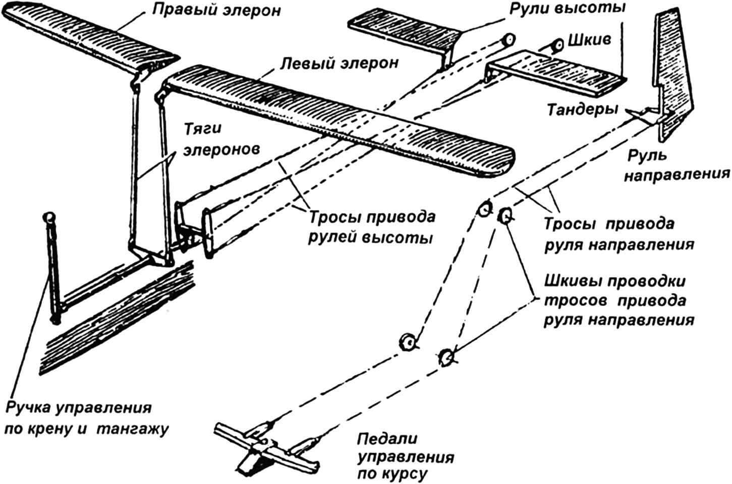
All these elements are extremely simple in design, convenient during assembly and disassembly, as well as during adjustment. All control system components are grouped on the fuselage truss, which is very convenient during operation and aircraft maintenance.
CONTROL ROCKER ASSEMBLY FOR ELEVATORS
The control rocker assembly for elevator control is a design feature of BRO-11M. When the control handle is moved “towards oneself” simultaneously with the upward deflection of the elevators, both ailerons deflect downwards by 10 degrees due to the original kinematics of the control linkage. This allows the glider to actively approach landing angles without a noticeable “nose-up,” making the glider’s landing simple, usually without “goats” and climbs.
ASSEMBLY OF THE GLIDER
The first assembly of the glider should be carried out in a well-lit room with dimensions of at least 10×8 m, pre-marking the main coordinates of BRO-11M on the floor – the axial line (trace of the symmetry plane of the aircraft), the locations of the wing, and the tail. A wire is tightly stretched exactly in the symmetry plane, on which several small plumb bobs are suspended on thin threads, designed for precise installation of the half-wings and tail, as well as for eliminating tilts of individual assembly parts and nodes.
The gondola must be fixed to the floor using temporary brackets and supports, after which the tail truss and half-wings are assembled. For this operation, you will need to make several stands, with which the assembly is carried out quickly and accurately.
To achieve the correct geometric shape of the glider, even tension of the cable braces is necessary. It should be noted that when weaving the cables, it is necessary to more accurately determine their length so that at the beginning of the assembly, the threaded tail pins can be screwed in manually without resorting to the use of a wrench.
After installing all the braces and evenly tensioning them with turnbuckles, you can proceed to the installation of the control cables for the elevators and rudder. They are tensioned not too tightly but without sagging.
After tensioning the cables, the turnbuckles [/caption] are secured with soft steel wire. With proper adjustment of the cables going to the rudder, its neutral position should correspond to the neutral position of the pedals. The same applies to the adjustment of the elevator; thus, in the neutral position of the elevators, the position of the control handle of the glider should also be neutral.
Elevators, when properly and carefully manufactured, require little adjustment.
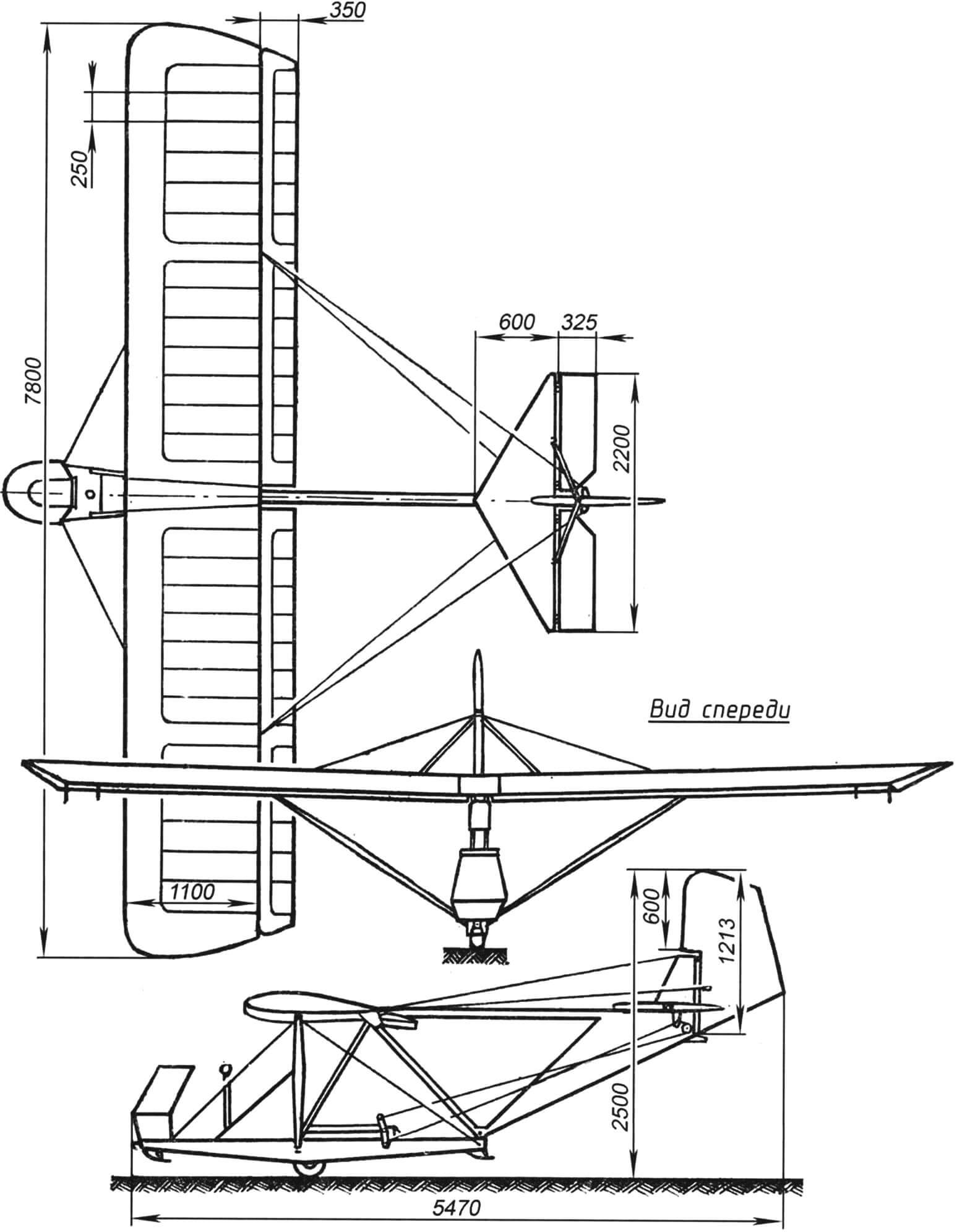
Aerotechnical characteristics of the glider BRO-11M
Wingspan, mm: 7800
Length, mm: 5470
Height on the ground, mm: 2500
Wing chord, mm: 1450
Wing area, m2: 11.8
Wing aspect ratio: 6.0
Wing sweep angle, deg: 3
Aileron span, mm: 3650
Aileron area, m2: 1.2
Aileron moment arm, mm: 1850
Fuselage length with beam, mm: 4520
Fuselage truss height, mm: 1240
Maximum fuselage width, mm: 510
Horizontal tail span, mm: 2200
Horizontal tail area, m2: 1.43
Elevator area, m2: 0.71
Horizontal tail moment arm, mm: 1820
Vertical tail height, mm: 2130
Vertical tail area, m2: 1.43
Rudder area, m2: 0.71
Vertical tail moment arm, mm: 2140
Glider mass with equipment, kg: 65
Useful load, kg: 60
Flight mass, kg: 125
Specific load, kg/m2: 1.8
Maximum quality: 12
Minimum sink rate, m/s: 1
Cruising speed, km/h: 40
Landing speed, km/h: 30
G. MALINOVSKY
Recommend to read
 “REPAINT” FOR THE FORGETFUL
This advice is specifically for those who know the situation when they are faced with aakriti the door forgetting the key at home. To avoid this, stick around the keyhole or lock glue...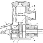 ENGINE — UNIVERSAL
To the editor of the magazine received a lot of letters in which modelers are asked to familiarize them with the device of the engine, designed by the Leningrad athlete E. Gusev. During...
