 In Amateur practice it is often required to provide an audible alarm, activated when the lighting of any object, the device responds to sudden illumination luminous flux working (photosensitive) surface of the photoresistor.
The principle of operation
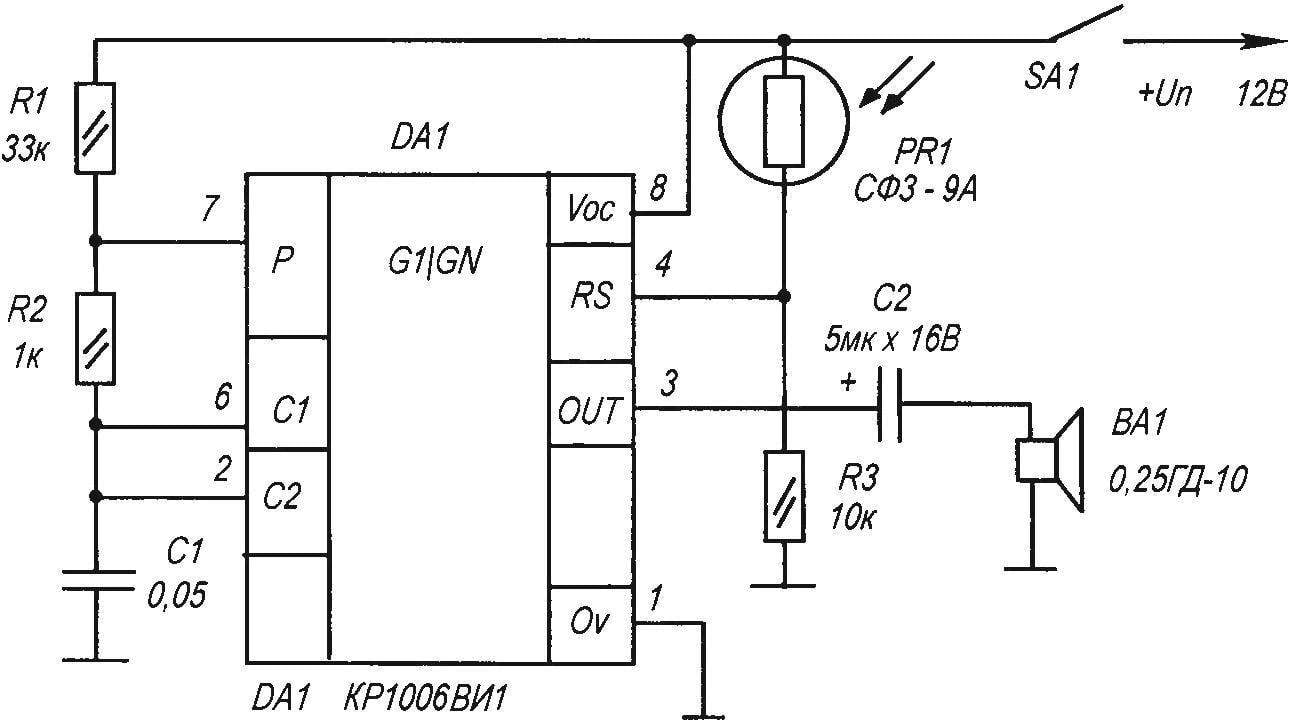
The simplicity of the schematics of this device is largely realized through the use of popular chips КР1006ВИ1 (DA1) Between pins 8 — 6 chips included a chain of two resistors R1R2 voltage Comparators (pins 2 and 4) control the switching States of the RS trigger. Conclusion 3 DA1 — relatively powerful (250 to 300 mA) output amplifier While illumination of the working surface PR1, the resistance of the photoresistor decreases to a few ohms, the current in its circuit increases and the chip DA1 acts as a generator of pulses of audio frequency. Rectangular pulses with a frequency of about 800 Hz (the sound sharp and loud) would come through a dividing capacitor C2, the dynamic head of BA1 Frequency and the pulse duration is governed by the capacitance of the capacitor C1 and the resistor R1.
Instead of a photoresistor SFZ-9A can be applied to other devices with similar electrical characteristics (e.g., FR-117 AND FR-764, FR-765, ФР75-AND, PPSS-2, PPSS-4, FSK-1). To increase the sensitivity of the node photoresistors are connected in parallel — two or three similar. The capacitor C2 prevents the impact load on the generator, he also does not pass the DC component of the voltage on the dynamic head.
Where to apply
This device is convenient to use as the audio alarm in the utility room If the light in the back do not light (what happens when no one in it), the generator does not work When entering in a room without Windows the uninvited guest photoresistor reacts to the inclusion of electric lights (and even light candles) and will put the violator in addition, applications for this scheme a lot.
Details
Fixed resistors type MLT-0,25, the Capacitor C1 is of type KM. To force shutdown the device (if you visit authorized controlled room) uses a switch SA1 (type П2К with fixation), which is hidden.

A circuit diagram of a sound signaling device under illumination of any object
Dynamic head — any, with coil impedance at least 8 Ohms, the Device stably operates in the range of supply voltage from 5 To 15 With increasing voltage the volume of the sound increases.
The power source for this node is stable. Current consumption in standby mode does not exceed 0.5 mA, which allows to use as a power source even batteries or low power batteries, D0, 26-D. In mode “alarm” in sound generation, the current consumption increases to 30…40 mA.
The device needs no adjustment and can be successfully applied as a separate sound node signaling.
Recommend to read
 BERRY RAKE
Since ancient times, people hunted their own food, collecting edible berries, Yes berries. The method of collecting the berries ever since has remained the same — squat or bend over to... CHOOSE A MOTOR FOR ALS
One of the main problems faced by the Amateur constructor engine aircraft — selection or production of the power plant the necessary power, weight and efficiency. This problem is solved...
