 Like many readers of “Modeller-designer”, my Hobbies are designing and making homemade equipment is therefore with special interest I read in the journal of machines and mechanisms created by craftsmen.
 For ploughing, harrowing, cultivation of the land on the plot made the winch, which trailer or a plow, or cultivator, or harrow. It has been in service for ten years.
Not so long ago built a self-propelled vehicle — a spark of uniaxial mototada and also a single axle truck, in the body which translate different loads (including the winch) Design Sparky invite readers to review And she is not quite normal. Such layout scheme is almost not used in transport equipment, but are often used in construction machinery (scrapers, grader-elevators, pneumococci, etc.). The speed of these machines is low, but the “tegometall” and maneuverability even with large-diameter wheels and with a significant size — is enviable.
Mini-truck looks like a walk-behind tractor with trailer cargo truck: he also has a motorcycle engine, no cab.
However, if more details to understand his scheme, it is similar to the circuit of the tractor T-150, or K-700 “Kirovets”. The truck has the same “broken” frame, and more precisely two articulated half-frames, the seats on the front frame (not on the trailer, like the tillers), and the steering-“bagel” — like wheeled tractor (or car) instead of two of the lever as the tillers.
Now about the design in more detail. The basis of mototada — frame consisting of two pivotally interconnected half-frames front (of the tillers) and rear (wagon) front frame-mounted powertrain, drivetrain, and two seats driver and passenger, or rather assistant-porter.
Front of frame — space, consisting of two parts: upper and lower. However, it is not difficult, the Upper part is a duplex spar comprising two longitudinal members made of channel No. 5 and are interconnected by several bridges steel area is 40×40 mm. the Rear ends of duplex spar is welded to the upper paleobase and front ends to Motorama.
The lower part of the front half frames made of round tubes with a diameter of 30 mm in the form of an arc of the envelope of the lower bearing race swivel joint, to which it is welded. The front ends of the rays of the arc is attached with screws M10 to the lugs of the bearing cage axle.
Between the rear ends of the longitudinal elements and the converging rays of the arc is mounted hinge joint with two pairs of radial bearings 80208. This node is assembled in the journal “modelist-Konstruktor” (sorry, I do not remember, in what room, and it doesn’t matter — still it upgraded). He has the ability to turn about a vertical axis, and horizontal. And this, in turn, eliminates hang-up of the wheels and reduces twisting of the frame. After the installation of the node on the top and bottom half frames (longitudinal and arc) of the front half frames sealed bolted down the two braces of steel pipes with a diameter of 20 mm with the flattened ends. They later assembled the handle shifter.
The rear frame is primarily mikolina beam of the truck and welded to the middle perpendicular to the shaft, Both parts are made of pipes with a diameter of 60 mm, and their connection is strengthened by the struts of a steel angle 30×30 mm. In the front end of the drawbar welded finger, carved from a steel circle with a diameter of 60 mm. Finger is inserted into the hinge connecting the two half frames. Here is the side welded to the drawbar pivot arm (made from angle 40×40), backed by the same brace.
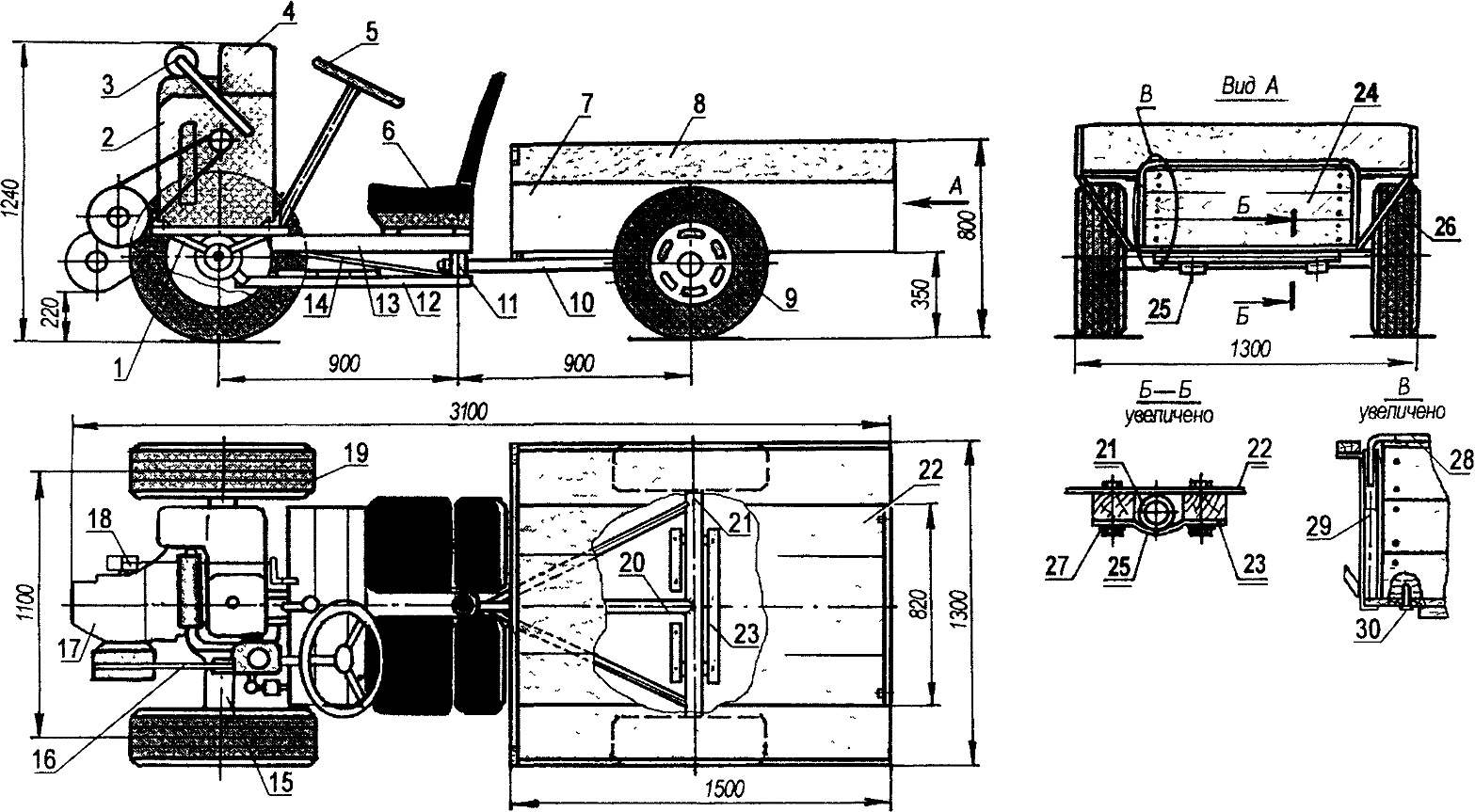
Mini truck with a broken frame spark mototada and a cargo truck:
1 — engine mount (area No. 4), 2 — the engine UD-1, 3 — damper, 4 — tank; 5 — the wheel 6 — seat (bus, 2 PCs); 7 — box body (sheet s1), 8 — body side (Board, s20), 9 — wheel truck (automotive, R13, 2-piece), 10 — brace hitch; 11 hinge; 12 — arc of the front articulated, 13 — spar front articulated, 14 — brace spar arc and the front half frames (tube Ø 20, 2 PCs); 15 — front driving axle (from harvester “Niva”, modified), 16 — transmission (V-transmission), 17 — gear shift in a block with clutch; 18 — brake, with 19 — front sprocket (automotive 205 R14, 2-piece), 20 — pole, 21 — axle trucks; 22 — bottom of body (Board s20); 23 — bars attaching the body to the beam (beam 60×40, 3 PCs), 24 — rear removable Borg, 25, a bracket attaching the body to the beam (the steel strip 30×5, 2); 26 — brace the sides of the body (area 30×30, 2 PCs.), 27 — mounting the body to the beam (bolt M12, 4-piece), 28 — the handle of the rear side (pipe Ø 16); 29 — bushing for shackle (tube Ø 22×2, 2 pieces), 30 —pin on the rear side (nail, 2 PCs.).
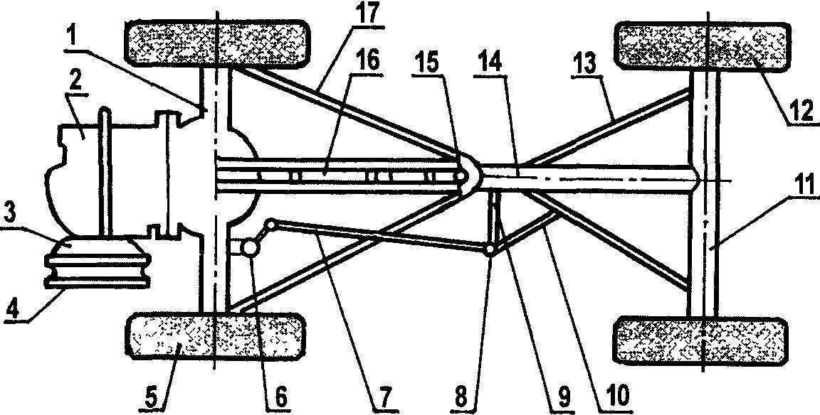
Scheme chassis no.:
1 — front drive axle main gear, differential and axle shafts, 2 — gear shift, 3 — a basket of coupling; 4 — a pulley-flywheel; 5 — front drive wheel (2 PCs); 6 — the steering mechanism with bipod, 7 — tie rod (tube Ø 30), 8 — tie rod end (from the car “Lada”); 9 — pivot arm (area 40×40); 10 — brace swinging arm (area 40×40), 11 — rear axle beam (tube Ø 60); 12 — rear wheel (2 piece), 13 — brace the rear of the drawbar articulated (area 30×30, 2 PCs.), 14 — pole rear articulated, 15 — jointed node, 16 — the rich — the upper part of the front half-frames (channel No. 5, 2 PCs), 17 — arc — the lower part of the front half frames (tube Ø 30).
The layout of the mini-truck.
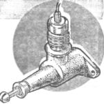
Hinge joint.
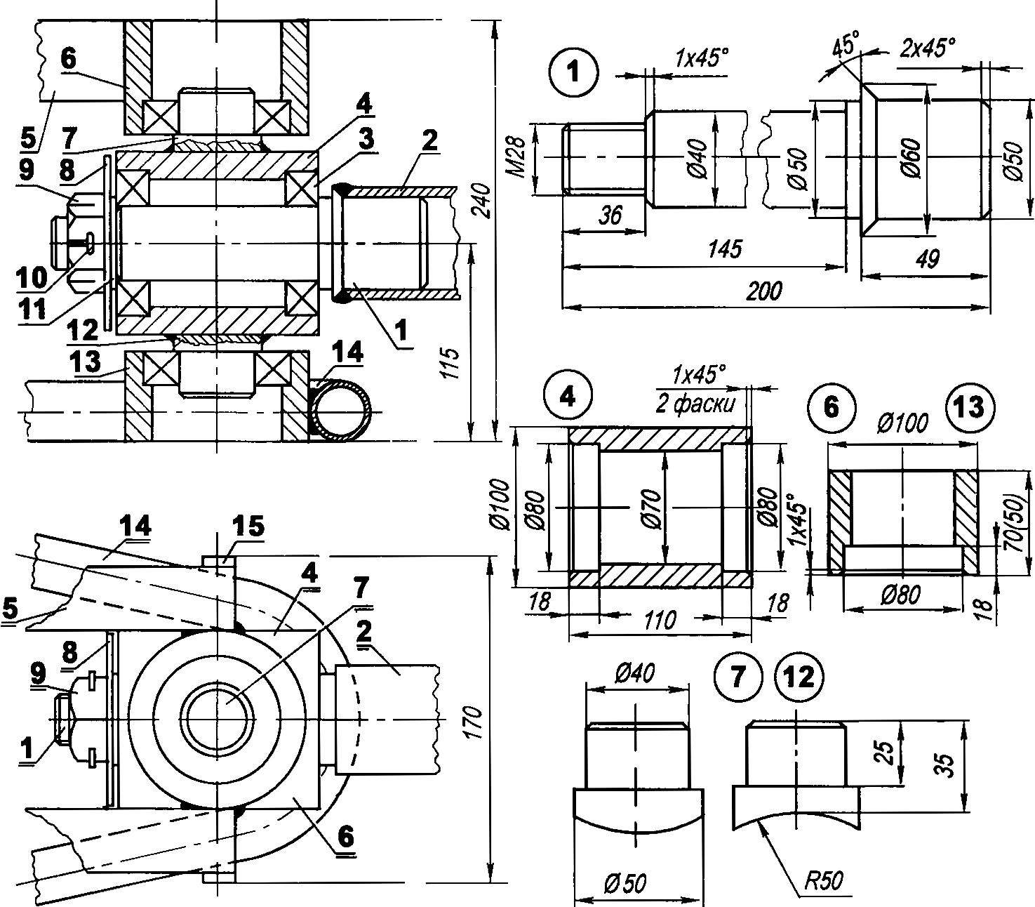
Attorney hinge:
1 — thumb (steel, round Ø 60), 2 — pole rear articulated (tube Ø 60), 3 — bearing 80208 (4 PCs), 4 — hinge bearing housing (steel, round Ø 100), 5 — spar front half-frames (channel No. 5, 2-piece), 6 — upper polumbaum (steel, range 100), 7 — upper vertical hinge pin (steel, circle 50), 8 safety washer (steel, sheet s3), 9 — nut M28, 10 — spring, 11 — thrust washer (steel, sheet s3), 12 — lower (vertical) axle (steel, circle 50), 13 — lower polumbaum (steel, range 100), 14 — arm front half frames (tube Ø 30), 15 — coupling (steel strip 15×3, 2 PCs.).
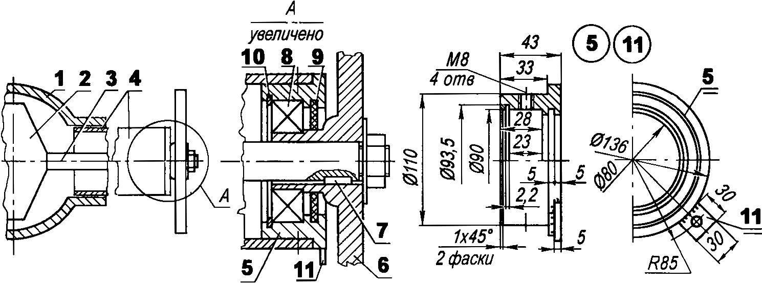
Alteration of the leading (front) axle from the combine:
1 — Carter, the main transmission and differential; 2 — the main gear with the differential, 3 — axle shaft (short, 2 PCs), 4 — stocking bridge (short, 2 PCs); 5 — bearing shell (homemade, 2 pieces); 6 — wheel hub (cut, drilled and mounted on the axle shaft); 7 — dowel (12 pieces), 8 — shaft bearing (2 PCs.), 9 cuff (2 PCs); 10 — lock washer (2 PCs); 11 — the eyelet the beam of the arc bottom of the front half frames (steel, sheet s5, 2 PCs).
Engine mottgage — UD-1, but you can use another, and the choice is quite wide. Only here the power unit with the capacity of more than six or seven horsepower to use is hardly appropriate. Even chetyrehkantnyj UD-1 is able to transport approximately 500 kg of cargo at speeds up to 30 km/h. At a higher load when starting off is slip of the driven wheels, and at higher speed observations — strong shaking and vibration due to the lack of depreciation of Equipment same tractor and truck soft suspension too would have complicated the design.
The engine is equipped with an air cooling system is Mounted on it Motorama directly over the front axle and has the ability to move in the longitudinal (in the direction of the tractor) direction to tension the belt the V-belt transmission with a ratio of 1:3 on the site of the pulley of the output shaft of the engine flywheel to the gearbox (transmission).
Engine mount the engine consists of two pairs of angles 4 Angles of the first pair with a length of 500 mm, welded to the bridge longitudinally at a distance of 400 mm from each other shelves up, and left the area on strut-braced racks. Another pair of angles attached directly to the engine, but shelves down and move transversely of the tractor.
Putting the top a couple of corners with the engine on the bottom corners and align the plane of rotation of the pulley and the flywheel, at the intersections of the corners of the drilled through holes with a diameter of 10.5 mm for the mounting bolts. After that, the shelves in the lower corners of the holes butchered grooves with a length of 50 mm. Instead of advancing motor and it is possible the use of idler belt.
Leading front axle (main transmission and differential) in the block with transmission used from decommissioned At the PPC processor was developed the neck shaft at the landing of the flywheel Here, I put on the epoxy binder metal foil and press on the flywheel complete with clutch, wearing release the clutch.
Transmission offers three speeds forward and one reverse, the gear shift Grip with rocker — homemade Wiring from lever to transmission — rigid rods and levers.
The reverse gear is used rarely — articulated and articulated frame design makes mototech very maneuverable and allows it to turn almost on the spot — around the axis of the coupling joint.
The flywheel in my design is used from a mower — it is smaller in diameter than regular. In the absence of such a flywheel can make teams out of the wheel hub suitable diameter and of the individual pulley In a simplified embodiment, it is possible to go without a flywheel and clutch, put the clutch pulley rigidly on the transaxle input shaft, and grip to implement a change in the tensioning of the drive V-belt by using the above mentioned roller.
The drive axle is also subjected to alteration factory width was about three meters first, removed unnecessary wheel motors and shortened the stockings with semi-axes In the ends trimmed stockings is pressed cage with the bearing and seals From rod cut off the flanges and shortened the Flanges are again planted on the axis, and now, these details are key.
The back of the truck speed or, more correctly, blocky Core box bottom is located between the rear wheels, It is made of sheet steel with a thickness of 1 mm, and its bottom — from the Board-“thirty” And the additional side (they are wooden) is arranged above the wheels, and therefore performs the function of the wings, at the same time increasing the cargo capacity of the Connection body parts (wooden and steel sheet) is made mainly on nails, and where necessary with the use of metal strips, the Bottom rests on the rear frame (I-beam, pole and struts) and is attached to a beam hinged by means of two brackets.
In the body of the removable rear wall, and the body can samoraspustitsya due to the shift of the center of mass of the cargo. Loading height is only 350 mm.
Steering: “steering wheel”, shaft, worm gearbox used from the car “Zaporozhets” ZAZ-966. A single tie rod connects the gear bipod with swivel arm welded to the end of the drawbar (or rather, to brace) rear articulated. The desire is made of water pipes with a diameter of 20 mm, and the bits taken from the car “the Zhiguli” the Brake is actuated from the crank and the clutch and “gas” — from the pedals as the cars to Admit the wiring of the clutch and gearshift are quite complex. Their simplification is my next task, and therefore I will not describe the existing.
Two seats (driver and assistant), taken from the cabin of a decommissioned bus, mounted on a common subframe on the front frame Under my feet there is a wooden floor.
V. POSAVEC, Pinsk, Belarus
Recommend to read
 THE MICRO CO2
Model airplanes still did not pay attention to a very promising engine, liquefied gas C02. But the simplicity of manufacture and operation make it much more affordable than compression and...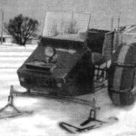 Ski Plus Pneumatic Tire
Whatever amateur designers may attempt, no better running gear for snowmobiles has yet been invented than the repeatedly tested combination of "ski plus pneumatic tire." I became...
