At the end of winter in 1974, on snow-covered fields near the airport “Domodedovo”, an unusual machine appeared—something like the egg of a fairy bird Rukh, or like a gigantic cocoon. Leaving behind clouds of snowy dust, it slid over the plain at an impressive speed and easily overcame fairly steep climbs. Its maneuverability astonished everyone: from a full run, the “cocoon” could turn literally in one place!
These were the second experimental aerosleds built at the Domodedovo public design bureau, led by young engineers Vladislav Maltsevsky and Alexander Podomatsky. A few years earlier, they had organized a youth design bureau in the settlement of Domodedovo, where many airport workers live and there are material opportunities to develop technical creativity using parts of aircraft that are periodically written off at the airport. The editorial office supported Vladislav’s initiative and his friends. Soon they also obtained a room: an unused transformer shed. The Komsomol committee and the leaders of the airport’s technical services helped them acquire the most necessary equipment; some of the boys brought things from home—each had a considerable amount of useful items for the intended collective work: parts, tools, and materials. That is how another original branch of the OKB “M-K” began its creative activity. Today, six engineers and technicians work there regularly. Many young people—mainly senior high school students from the local school—come in the evenings to the workshop and, on a par with adults, take part in creating interesting samples of transport engineering. The main focus of the Domodedovo OKB is the development of all-terrain vehicles. Following the aerosleds we tell readers about in this issue, another amazing machine appeared on the test stand: a motor-roller amphibian. By the designers’ concept, this device should combine the properties of an individual land transport vehicle and a one-seat motorboat. It is being created based on the motor-roller “Tula-tourist”, produced by the domestic industry.
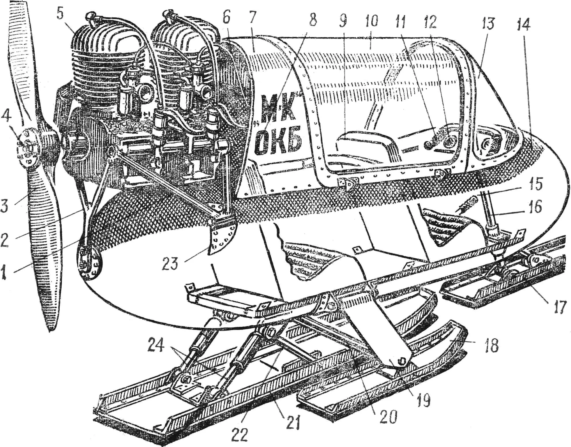
Fig. 1. Overall layout of the aerosleds:
1 — fairing of the forward part of the body, 2 — rear fork of the motor frame, 3 — propeller, 4 — propeller hub, 5 — engine (twin installation of two motorcycle engines “Jawa-250”), 6 — fuel tank, 7 — fairing (gargrout), 8 — rear seat, 9 — front seat, 10 — hinged part of the canopy, 11 — motorcycle-type handlebar, 12 — instrument panel, 13 — front (fixed) part of the canopy, 14 — front nacelle (cowl), 15 — steering shaft, 16 — brake lever, 17 — front (steering) ski, 18 — side ski, 19 — side ski suspension strut, 20 — side ski brace, 21 — main ski, 22 — main ski bracket, 23 — main ski shock absorbers, 24 — side attachment for the motor frame.
…And on the drafting table covered with a curtain, the outlines of a small-sized trimaran are also drawn—of an equally unusual design, with folding side floats. The model of this machine has already been tested and has shown promising results. Soon the construction of the full-size machine will begin.
The Domodedovo OKB participates in a number of all-terrain vehicle review-and-contest events. At the traditional winter holiday in the Moscow Region city of Khimki, aerosleds from Domodedovo took part in demonstration competitions and were awarded diplomas of the magazines “Modelist-konstruktor”, “Tekhnika — molodezhi”, and DOSAAF’s GK.
How the aerosleds were created in the public design bureau “Domodedovo” is told by the project leaders, engineers Vladislav Maltsevsky and Alexander Podomatsky. “Sometimes we are asked why, having organized a youth public design bureau, we started building aerosleds instead of something else. It is hard for city residents accustomed to clean asphalt streets even in snowy winters to understand this. Around our Domodedovo, snow lies in a thick carpet from November to April, and its gleaming white blanket keeps inviting—inviting to ride with the wind, without worrying about the road, about ice formation, drifts, and snow slides. That is exactly why, when discussing the work plan, our small creative team firmly decided: the first development should be aerosleds. Technical requirements for the design: increased cross-country capability, good aerodynamics, and the maximum possible comfort for the crew. Passenger capacity — two people, including the driver; engine power 25—30 hp.”
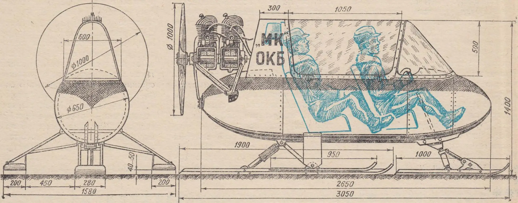
Before starting the design, we got acquainted with many aerosleds built by hobbyists. At the sketch-project stage, we tried to borrow everything good we saw and, as far as possible, to avoid the shortcomings typical for one design or another. We really liked the sleds by Valery Kukin (see “M-K” No. 10, 1970). However, from the turning-control system proposed by him, we decided to give up and instead use a conventional front steering ski: it is more reliable on loose snow. In other respects, our sleds are similar to Valery Kukin’s: the main skis (steering and load-bearing) are arranged one behind the other according to the “bicycle” scheme; the supporting skis are on the right and left of the body (Fig. 1). We knew that this arrangement is more advantageous on snow-covered wilderness, on non-packed snow, when riding along forest paths and through shrubs. The body has a subframe—an underlying structure (Fig. 2); welded from rectangular-section steel tubes, it serves as a base to which the steering and load-bearing skis are attached on spring shock absorbers. The auxiliary side skis are made to be removable and are installed rigidly on brackets welded from thin-walled steel tubes. The center of pressure of the side skis coincides with the center of gravity of the loaded aerosleds in the plane perpendicular to the direction of travel, which favorably affects the stability of the machine.
The load-bearing ski is made from sheet steel 1 mm thick and reinforced with four longitudinal duraluminum angle pieces 30×30 mm. It is attached to the base in a hinged manner using a rocker frame welded from thin-walled steel tubes, and is sprung on spring shock absorbers from the moped “Riga”. The steering ski is suspended in the same way. Its shaft, ending in a steering wheel in the driver’s cabin, is attached to the body subframe at three points, equipped with textolite inserts to reduce friction. The steering and both side skis—made of 2.5 mm thick sheet duraluminum—are reinforced with longitudinal duraluminum angles 25×25 mm.
The outer body shell is made from two aircraft engine cowlings of the Il-18 (rotating body) and an intermediate cylindrical insert of duraluminum sheet 2.5 mm thick. The canopy consists of a non-removable (rigidly attached to the body) streamlined front part and a rear cylinder-shaped cover hinged to open to the sides. Successful proportions of the body and canopy give the machine a very compact appearance. The seats are arranged one behind the other so that the feet of the passenger sitting at the back fit on the sides of the front seat. This made it possible to shorten the body to the extreme and save some weight.
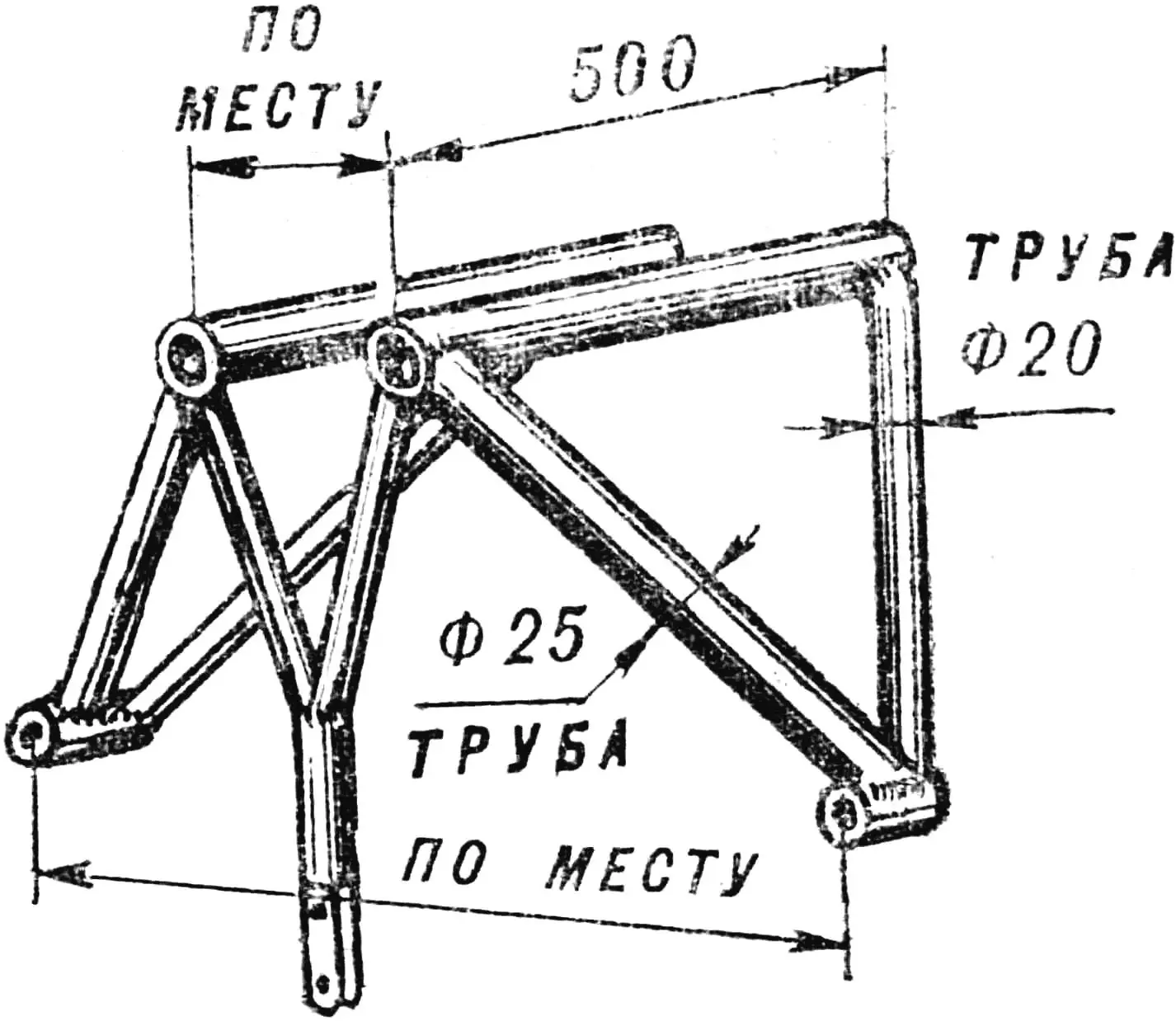
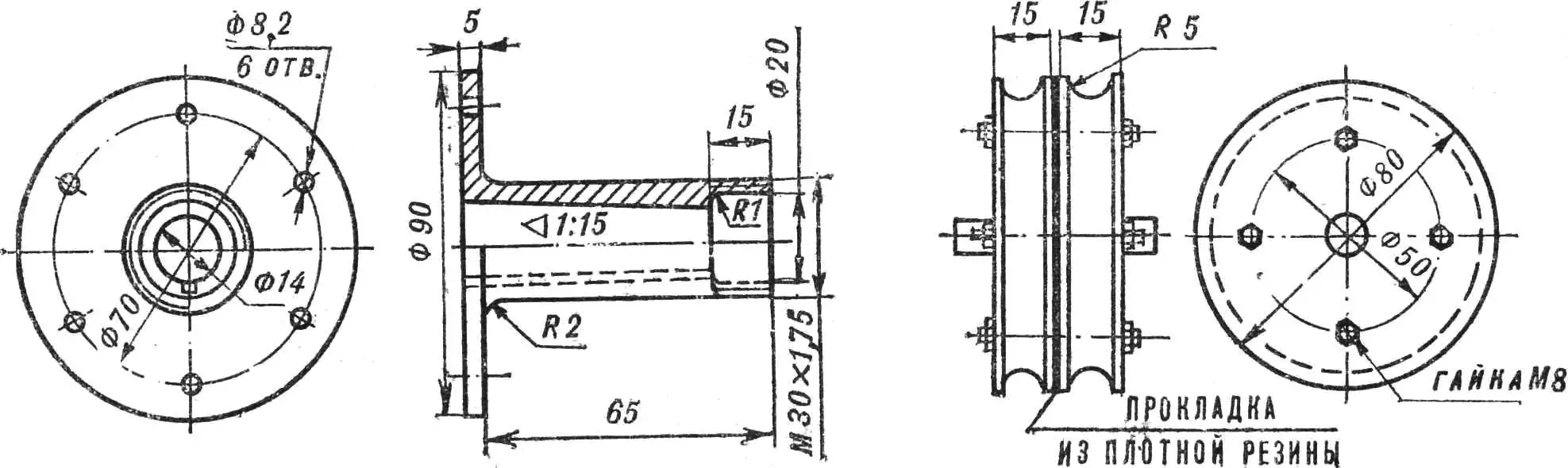
The aerosled motor installation is easily removable, mounted on a special welded tubular subframe attached to the body at three points (Fig. 4). The subframe is quickly dismantled together with the engine and can be installed on any other machine. The engine was created based on two motorcycle engines “Jawa-250” arranged one behind the other, with the gearboxes cut off and the crankshafts connected by an external rigid coupling. During experiments with the engine, we also tested a semi-rigid connection scheme using a rubber seal. The tests showed that the rigid scheme is more reliable and simpler. As is known, for such a connection a high precision of mating the working surfaces is required. We achieved this by grinding the half-couplings on a lathe, already mounted on the crankshaft tails. The crankshaft remains in the engine housing mounted on the machine tool’s support, and is rotated evenly by hand. The grinding allowance is within 0.2—0.3 mm. The coupling is provided with a groove for the starting pull cord (Fig. 5).
When removing the gearbox, clutch and starting housings, the frames must be cut so that the remaining part preserves the mounting holes for the secondary-shaft bearings. When coupling the engines, a calibrated steel pipe with thread on both ends is inserted into these holes; this pipe serves simultaneously as a fastening and centering element (see drawing 1). The second centering element is the rigid coupling itself, which pulls together the ends of the crankshafts.
For greater rigidity, the engine housings are additionally connected with spreaders.
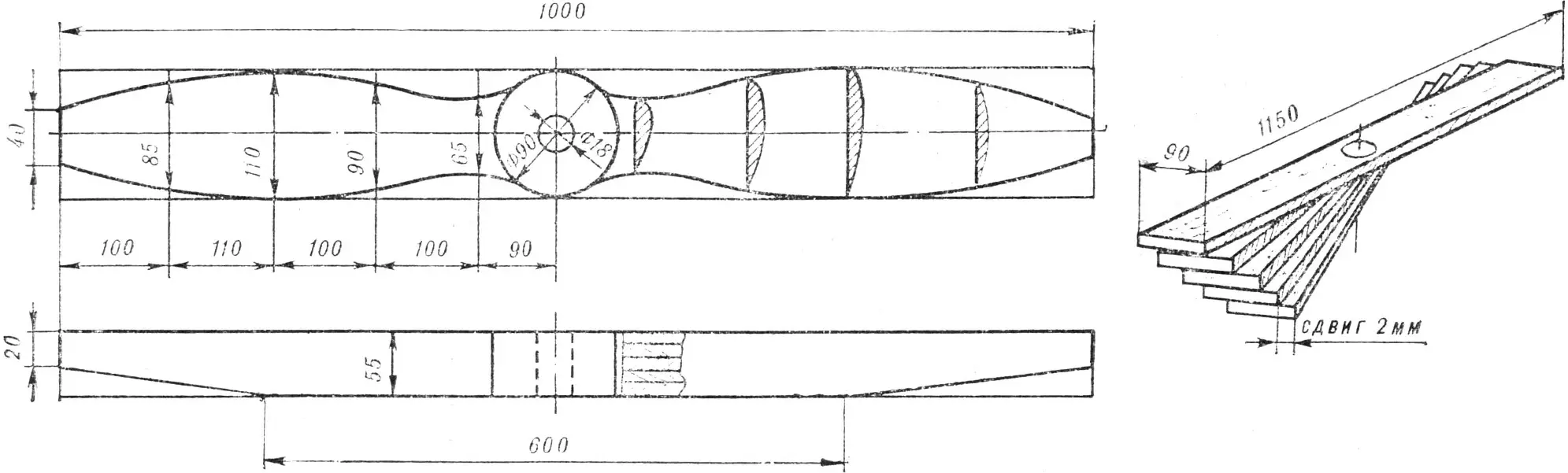
The aerosled propeller is left-hand rotation, Ø 1.0 m, pitch 450 mm, glued from drok (Fig. 3). The blades are covered with a single layer of glass-fiber cloth ASTT(б) and then polished. The propeller is mounted directly on the crankshaft tail. The hub is shown in Fig. 5.
The ignition system we used from the motorcycle “Jawa-350” was modified. The changes primarily affected the breaker unit. Its base is fixed on a rotating bracket, which allows setting the optimum ignition lead angle depending on the engine operating mode. Ignition lead control is synchronized with the throttle opening. This ensures reliable and safe starting, stable operation at low rpm, and maximum power delivery at the limiting operating mode. Fuel supply is by gravity from a tank installed above the engine. On the aerosled instrument panel there is an electrical tachometer (made according to the scheme published in the magazine “M-K” No. 5 for 1973), a cylinder-head temperature indicator, and a two-pointer speed indicator with a scale from 20 km/h.
Over two seasons of operation, no serious design defects were detected. The maximum speed on packed snow is about 50—55 km/h.
«М-К» 2’78, V. MALTSEVSKY, A. PODOMATSKY, engineers
Recommend to read
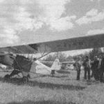 “PERSISTENT” ASKS IN THE FLIGHT
So call your plane the club-model airplanes and their leader — Vadim B. Rumyantsev from the city of Privolzhsk, Ivanovo region, whose hands at the local station of young technicians...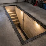 Comfortable renovation
I suggest motorists equip themselves with a shallow inspection pit that lets you repair a car while seated. It takes far less effort and material than building any “full-depth” equivalent...
