Choosing a suitable engine for aerosleds is a far from simple task. Series engines, for many parameters (in particular, specific power), do not satisfy amateur designers. That is why some enthusiasts choose a rather complex, but correct, path: to create motors of their own design using units and parts from series engines.
The editorial office has repeatedly provided pages of the magazine to amateur designers, describing the principles of engine design and the technology of manufacturing them. Thus, readers took a special interest in F. Kizelov’s article (“M-K” No. 6, 1978), in which the manufacturing technology of an opposed engine was described — an engine that has a number of advantages compared with engines of other layouts. This article is about improving the “opposed engine”.
At the Troitsk city station for young technicians we built several aerosleds and karts. The main engine we used was the tractor starter PD-10. What we didn’t do with these motors: we boosted them and also coupled them, but we still couldn’t achieve the desired results. The motors were heavy, bulky, and had comparatively low specific power; and for the boosted variants, the engine life was also not good. We tried increasing power by improving scavenging, but that also didn’t help.
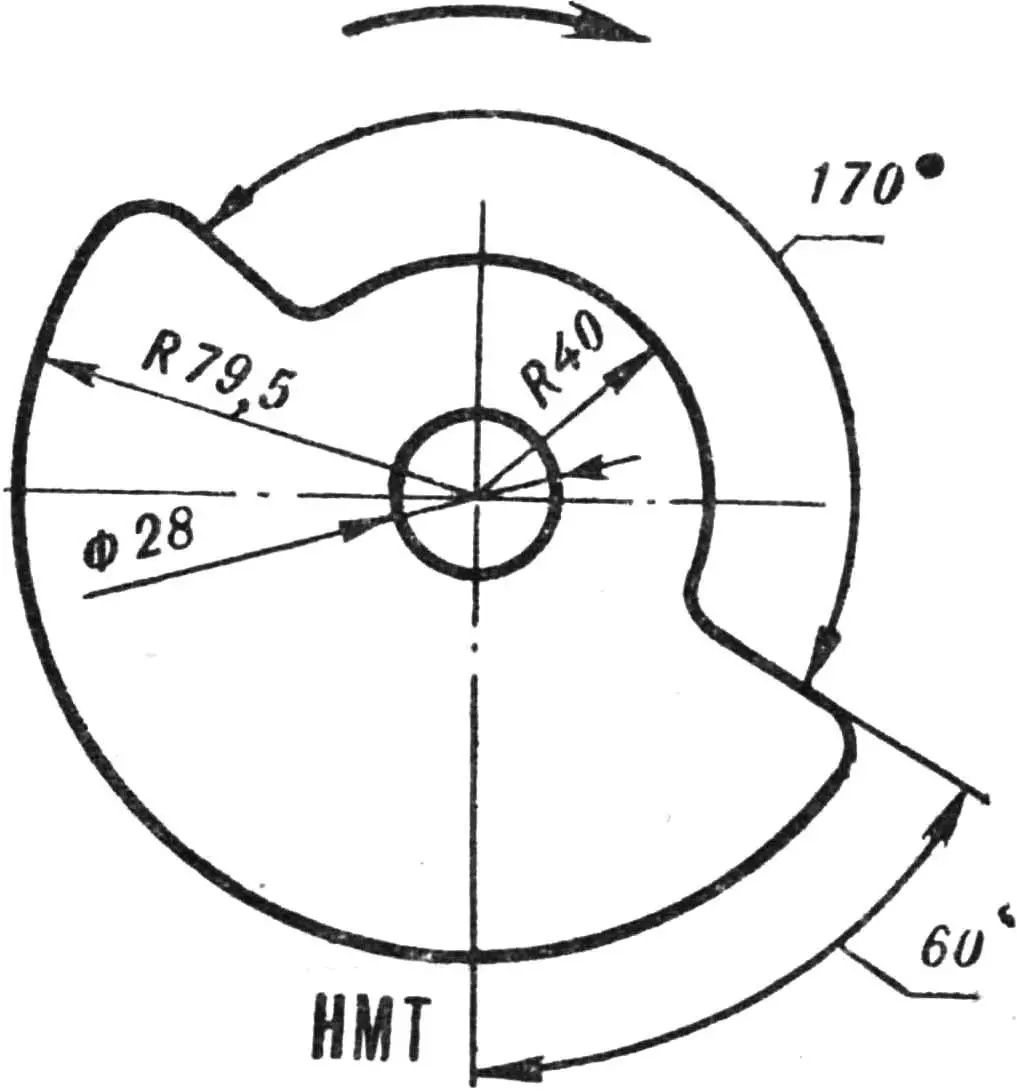
1 and 2 — start and end of scavenging (156°), 3 and 4 — start and end of transfer (120°), 5 and 6 — start and end of intake when controlled by the spool valve (170°), 7 and 8 — start and end of intake when controlled by the piston (146°).
The point is that in the vast majority of two-stroke engines, the piston controls the intake of the fuel-air mixture into the crankcase. It opens the window without reaching 60—65° to top dead center (TDC), and closes it after the same 60—65° have passed following that point. Thus, the intake timing is symmetrical about TDC, and there’s nothing you can do about it, because the relative position of the window edges and the piston during its motion both upward and downward is the same.
To improve cylinder filling with the mixture, intake should preferably start 130—140° before TDC and finish 40—50° after.
And such engines do exist — with a disc spool valve or with a reed valve controlling mixture intake. They have become widespread only recently. Distribution using a disc spool valve makes it possible to reach a power per liter of about 130 hp.
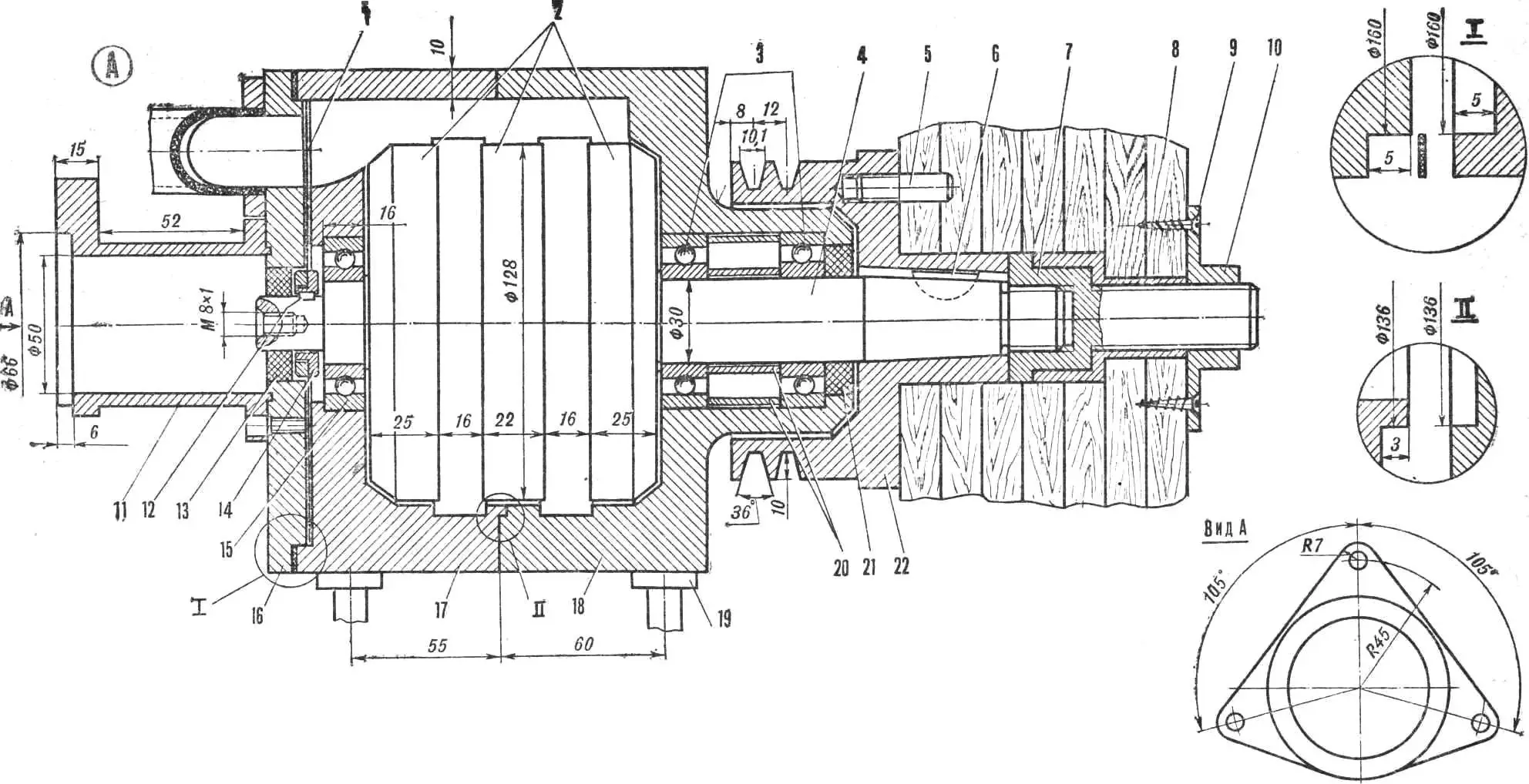
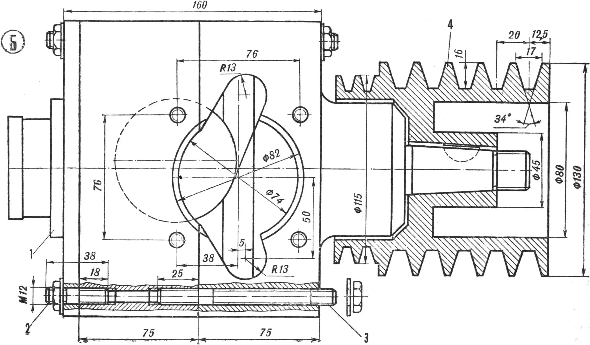
The disc spool valve installed on our new engine is a shaped steel plate 0.4—0.6 mm thick (steel 65G). Geometrically, it consists of two articulated circular sectors of different radii with smooth transitions between them. The disc is mounted on the crankshaft journal and rotates in a narrow slot formed by the left half of the crankcase and the spool valve cover. Intake openings are machined in the cover and the crankcase; the carburetor connection pipe is welded from duralumin tubes and attached to the flange of the crankcase cover.
The disc spool valve operates as follows. As the disc rotates, the moment comes when the disc cutout lines up with the openings in the cover and crankcase. This opens access for the fuel mixture to the crankcase from the carburetor. The duration of intake is determined by the width of the cutout in the disc. In our engine, the intake phase is 170°, but it is likely that the optimal angle should be selected experimentally, i.e., gradually increase the cutout in the disc while simultaneously measuring the crankshaft speed with a tachometer. In this way, you can achieve the optimal intake duration, and therefore the maximum torque on the engine shaft.
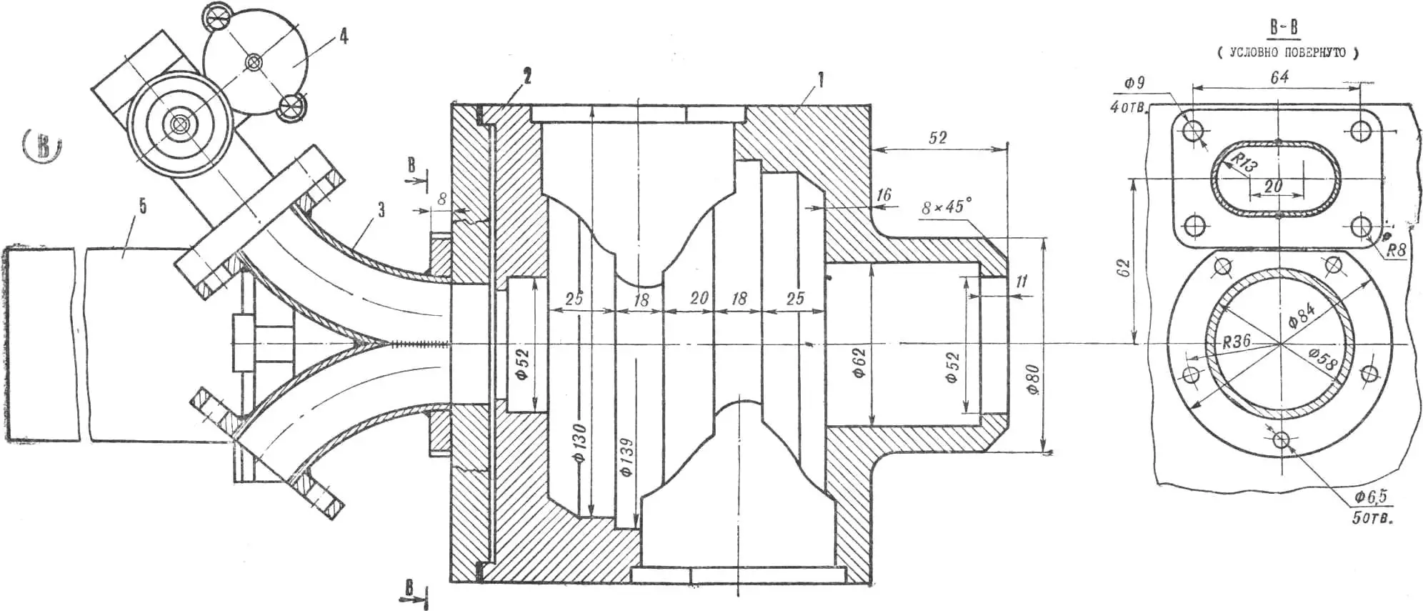
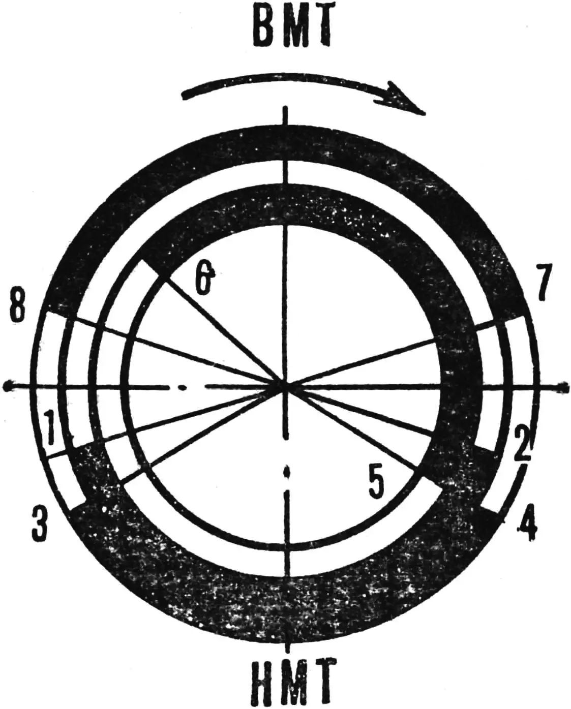
A — design of the spool-valve engine in the version with a propeller: 1 — spool valve, 2 — crankshaft cheeks, 3 — bearings of the right support, 4 — crankshaft journal, 5 — pin, 6 — segment key, 7 — nut, 8 — screw, 9 — locking screw, 10 — nut, 11 — magneto mounting cup, 12 — key, 13 — oil seal, 14 — bushing with nut for spool-valve mounting, 15 — bearing of the left support, 16 — spool valve cover, 17 — left crankcase half, 18 — right crankcase half, 19 — engine mounting stud, 20 — spacer bushings, 21 — oil seal, 22 — propeller hub bushing with generator drive pulley.
B — installing the multi-groove pulley on the engine: 1 — breaker housing, 2 — stud for fastening the spool-valve cover, 3 — stud for fastening the crankcase halves, 4 — multi-groove pulley.
C — crankcase and the engine’s main units: 1 — right crankcase half, 2 — left crankcase half, 3 — manifold pipe, 4 — carburetor 2926SBD (“Jawa”), 5 — magneto M-42.
On the crankshaft, the spool disc is mounted via an intermediate bushing and fixed on it with a nut. The bushing itself is seated on the left crankshaft journal and can move axially along it between the housing wall and the spool valve cover. The clearances between the spool and the cover, and between the spool and the housing, should be within 0.4—0.5 mm; they are adjusted by selecting suitable gaskets.
If such an engine is intended for an aircraft, where the weight of the design is of primary importance, it is best to use a magneto of the M-42 type. When using the motor on ground (or water) transport, it makes sense to use either a contactless ignition or a conventional ignition with a breaker. In the latter case, you can take two six-volt coils from Jawa or IZH motorcycles and the corresponding generator (for example, G-424 with an RR-330 relay-regulator).
«M-K» 4’80, A. Kozhakhmetov
Recommend to read
 C-27J
C-27J
A cargo aircraft C-27J "Spartan" set up jointly by the Italian company "Alenia Arepas" and the American "Lockheed". Its predecessor—the Italian light military transport aircraft G. 222",... VALVE OF THE ENGINE FOR THE MAP
(The end. Beginning in № 12, 1974) In the previous issue of master of automobile sports of the USSR M. Todorov spoke about how we need to begin work on the boost engine, providing...
