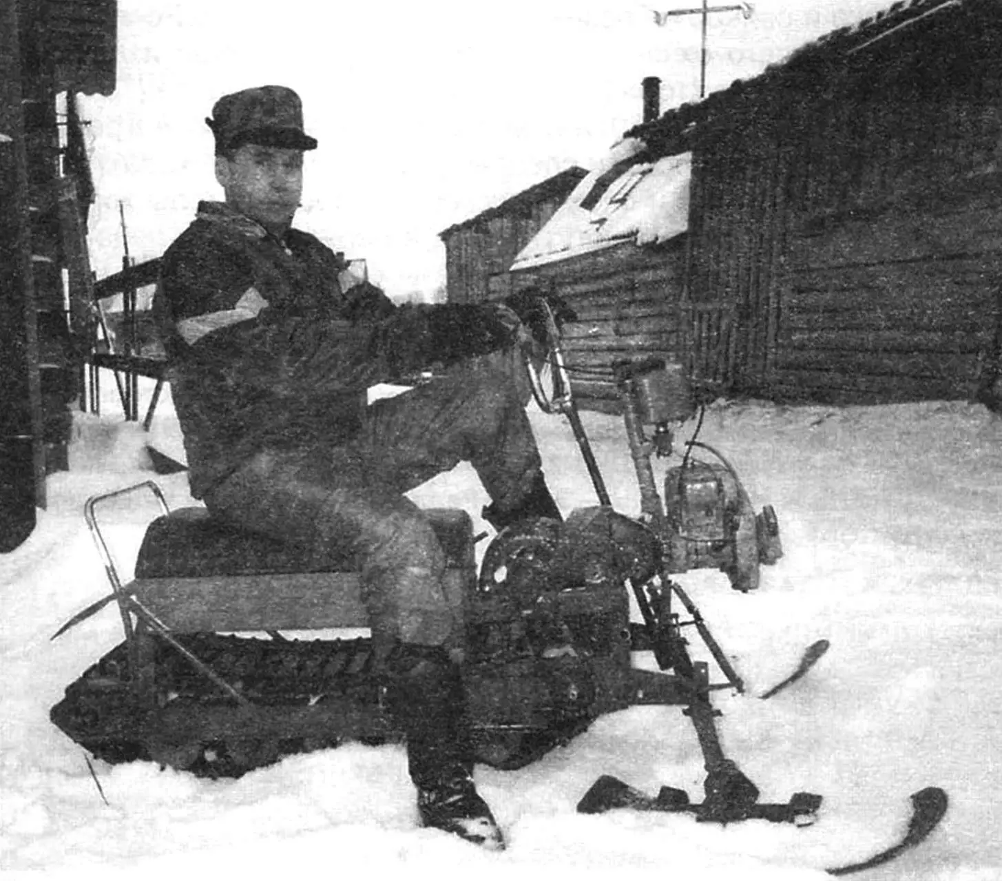
Winter in our northern parts is long. There aren’t many roads, and even those don’t manage to clear snow in time. That’s why it’s hard for people here to get by without snowmobile machines, especially when you often have to ride completely off-road (for example, into the forest for firewood) — right across piled-up snowdrifts. However, buying a snowmobile isn’t affordable for everyone, even if it’s not too expensive — domestic. So those who can make such a machine with their own hands have to design it according to their own project — for the parts and assemblies that the craftsman has. The snowmobile that I’ll talk about isn’t my first one (see “Modelist-konstruktor” No. 11 for 2004).
The old gasoline-powered chainsaw “Ural” pushed me to build the second snowmobile — it had been lying unused in the garage for a long time because the tire and chain were completely worn out.
However, the engine itself was in order — I repaired it before storing it away. The gearbox was also fine. These two mechanisms are what I decided to use in the snowmobile. In my mind, the construction matured too — more precisely, the layout of the power unit and the transmission scheme. As much as possible, I picked up and stocked other parts and units: for example, I decided to adapt skis from a children’s snow scooter, and the track from the old snowmobile “Buran”.
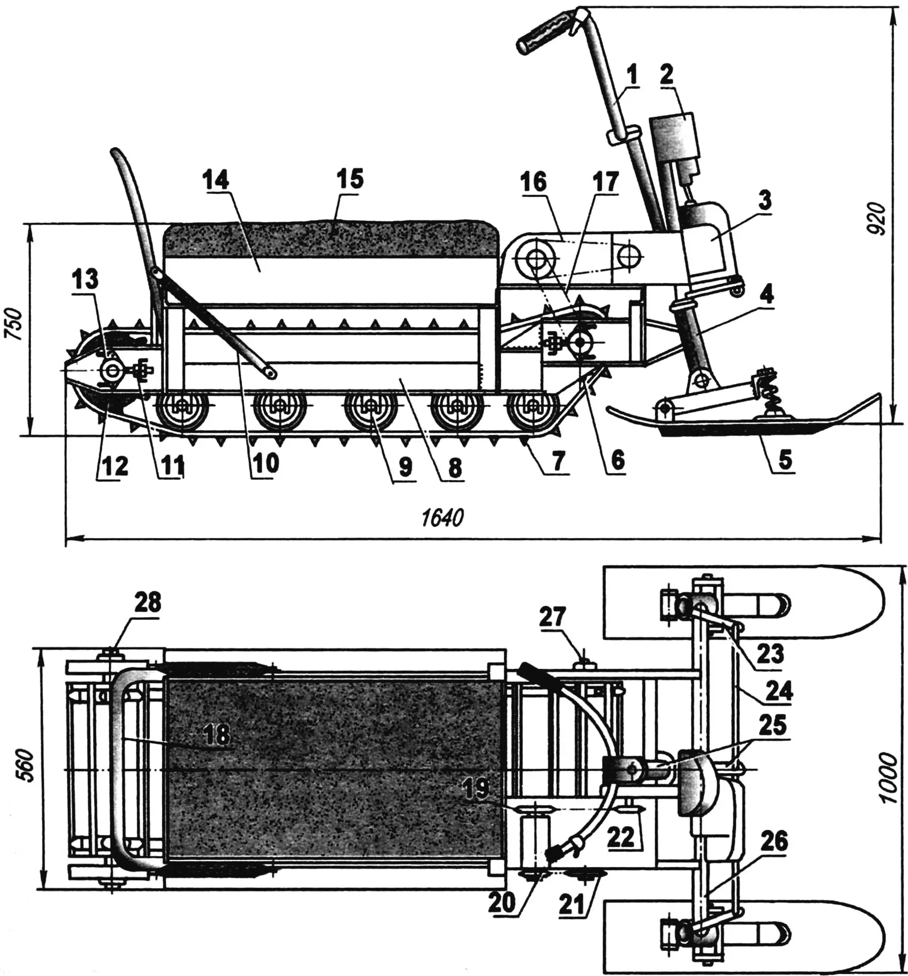
1 — steering handle; 2 — fuel tank (from the “Druzhba” chainsaw); 3 — power unit (from the “Ural” chainsaw); 4 — bushing of the steering ski stand (pipe Ø30, 2 pcs); 5 — steering ski (2 pcs); 6 — drive sprocket of the track (capron sheet s15, 2 pcs); 7 — track (from the “Buran” snowmobile, shortened); 8 — frame; 9 — support roller (from a potato sorting unit, 18 pcs); 10 — strut of the seat back limiter (pipe 16”); 11 — track tension device (2 pcs); 12 — track tension sprocket (capron sheet S15, 2 pcs); 13 — bearing No. 80204 in the housing (4 pcs); 14 — storage box / trunk (bottom — plywood s4, sides — board s20); 15 — seat (lid—plywood s4, foam rubber, leather substitute); 16 — 1st stage of the chain transmission; 17 — 2nd stage of the chain transmission; 18 — seat back limiter (pipe 1/2”); 19 — driven sprocket of the 1st chain stage (the larger sprocket of the speed reducer — the intermediate shaft), z = 38; 20 — driving sprocket of the 2nd chain stage (the smaller sprocket of the speed reducer), z = 10; 21 — driven sprocket of the 2nd chain stage (the sprocket that drives the leading shaft of the track), z = 18; 22 — driving sprocket of the 1st chain stage (sprocket of the output shaft of the gearbox), z = 12; 23 — lever of the steering knuckle; 24 — steering rod (2 pcs); 25 — steering shaft with a tie-rod (swarf) / bell crank; 26 — front axle beam (pipe Ø30); 27 — track drive shaft; 28 — track tension axis
Based on the dimensions of the main units and assemblies, I started to design the winter machine I had in mind. Although the word “design” is probably too loud in this case. More likely, it was the process of roughly estimating the mutual arrangement of mechanisms, since I didn’t make any drawings or sketches. The ones shown in the material, I made already from the finished construction, to present the snowmobile to the journal’s readers, because overview photographs don’t give a full picture of the machine.
I’ll start the description of the snowmobile’s construction with the frame. Its foundation, as well as the tracked unit block, consists of two welded longitudinal members (longeons). The middle portion of each of them is made from a steel angle 50×36 mm, and the front and rear parts are made from 2 mm steel plates with flanges bent at 90° (for stiffness). In each of these plates, through slots / holes are machined: in the front — for the track drive shaft, and in the rear — for the axis of the guide (and at the same time tension) sprockets. The tension devices are mounted on both ends of the longitudinal members. The front device is used to tension the 2nd stage of the chain transmission and, at the same time, provides adjustment of the track tension in wider limits than if there were only the rear device.
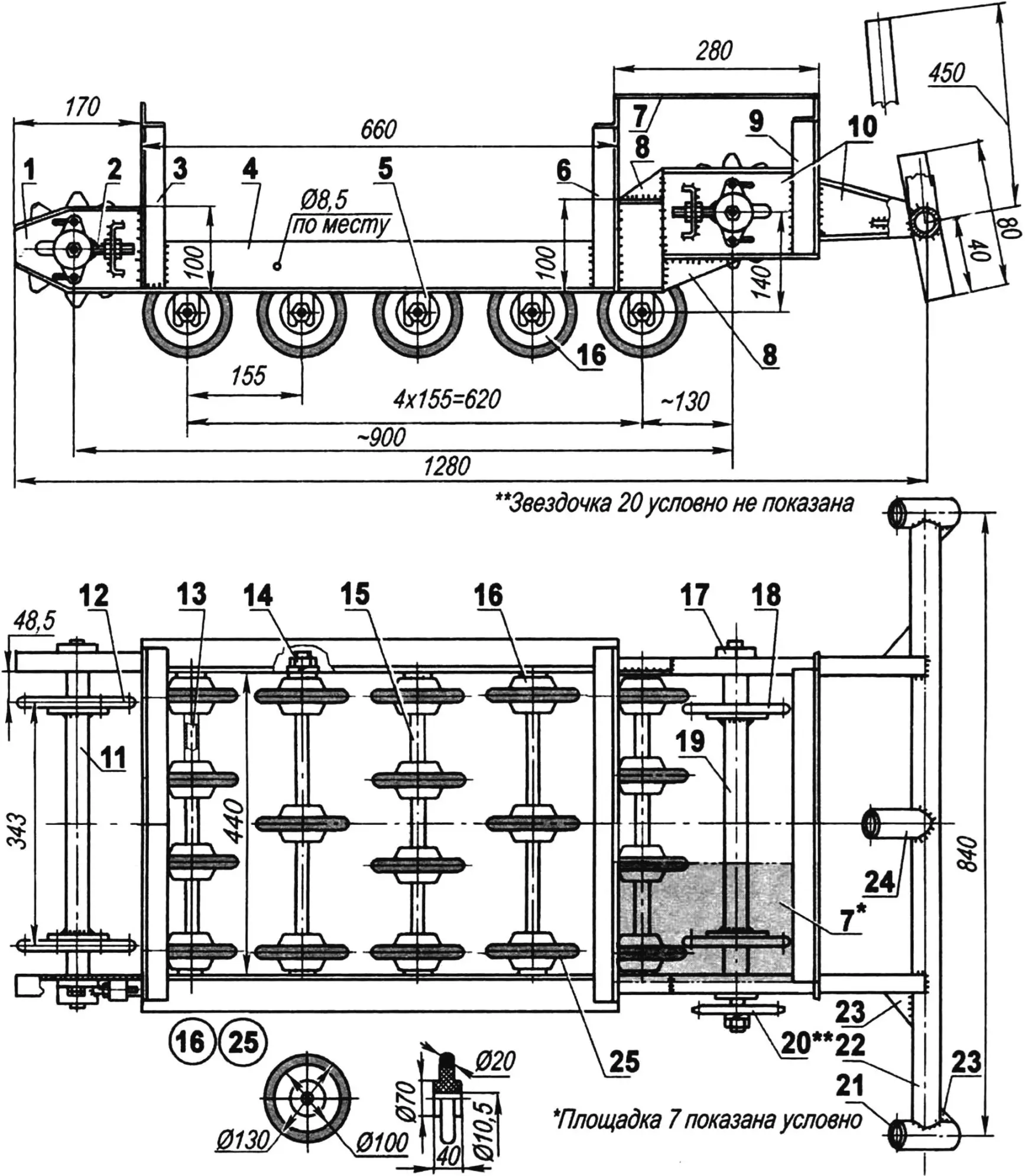
1 — rear part of the longitudinal member (steel sheet s2, with flanges, 2 pcs); 2 — tension device (4 pcs); 3 — rear portal (angle 30×30); 4 — middle part of the longitudinal member (angle 50×63, 2 pcs); 5 — bracket-fork for mounting the axle of the support rollers (steel sheet s2, 10 pcs); 6 — middle portal (angle 30×30); 7 — platform for mounting the gearbox of the power unit and the intermediate shaft-speed reducer (steel sheet s2); 8 — gussets / braces (steel sheet s2, 4 pcs); 9 — front portal (angle 30×30); 10 — front composite part of the longitudinal member (steel sheet s2 with flanges); 11 — axle of the tension sprockets; 12 — track tension sprocket (2 pcs); 13 — axle of support rollers (steel, circle 10, 5 pcs); 14 — axle mounting (M10 nut and spring washer, 20 sets); 15 — spacer bushing (duralumin pipe); 16 — roller (18 pcs); 17 — bearing unit (4 pcs); 18 — track drive sprocket (2 pcs); 19 — track drive shaft; 20 — driving sprocket of the leading shaft (driven sprocket of the 2nd stage of the chain transmission), z = 18; 21 — bushing of the steering knuckle on the steering ski (pipe Ø30, 2 pcs); 22 — front axle beam (pipe Ø30); 23 — braces / gussets (4 pcs); 24 — engine mounting stand (pipe Ø30); 25 — roller bandage (rubber ring, 18 pcs.)
From below, brackets are welded to the longitudinal members at equal intervals — in their open slots on the underside, the axles of the support rollers are inserted. The rollers are arranged on five axles (three or four on each), with the outer axles having rollers on every place, and the middle rollers in a checkerboard pattern.
Since the subject is the support rollers, I’ll note here that there are 18 of them in total, and they are borrowed from a written-off potato sorting unit. The rollers are made of capron and also “shoed” in rubber tires.
The axles of the rollers are also taken from an agricultural unit — only from a different one, a potato-digger. The ends of the axles had to be annealed so that they could be machined and threaded to M10 here. Between the rollers on the axles, spacer bushings made of duralumin pipe of the appropriate diameter are fitted. The axles are fixed in the brackets on each side with a nut and a lock nut. You can also add that each axle additionally serves as a cross brace for the frame, keeping the longitudinal members at a specific distance from one another — because there are no other fixing elements in the middle and rear portions of the longitudinal members.
For each longitudinal member, three stands made of a steel angle 30×30 mm are welded, connected by the same crosspieces. Two stands and the crosspiece between them form a small portal. Between the front and middle portals on the right side, a platform is made from a steel 2 mm sheet — on it, the chainsaw gearbox and the intermediate shaft of the chain transmission are later mounted. Between the middle and rear portals, a fairly large box is arranged, whose lid serves as a seat — but I’ll tell about that later.
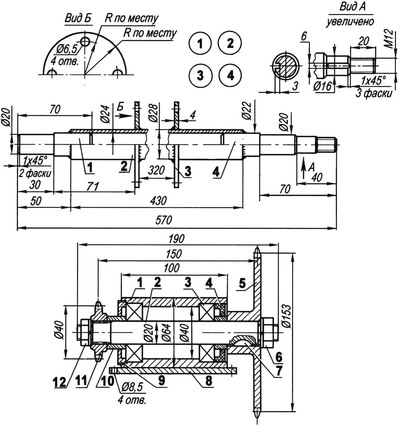
1 — bearing housing body; 2 — shaft; 3 — bearing 80204 (2 pcs); 4 — oil seal / seal; 5 — large sprocket z = 38; 6 — M20 nut fastening the large sprocket with a spring washer; 7 — segment key; 8 — base of the body; 9 — threaded cover M60; 10 — spacer bushing (2 pcs); 11 — small sprocket z = 10; 12 — M14 nut fastening the small sprocket with a spring washer
The front ends of the longitudinal members are welded to the transverse beam (traverse) of the front axle (in fact, there is only one axle because the rear axle simply doesn’t exist). The beam is made from a steel water-pipe with an outer diameter of 32 mm. At its ends, bushings for the steering skis are welded, and in the middle — a stand that serves as an engine subframe / motor cradle. Both the bushings and the stand are made from the same pipe as the beam itself. The connection points of the bushings and the stand to the beam are reinforced with gussets welded from a steel 2 mm sheet.
As it’s clear from what I said above, the snowmobile’s propulsion is tracked. The track, as noted earlier, is taken from the old “Buran”, but shortened by half a meter and sewn from a section of a conveyor belt.
The track sprockets, both drive and tension, are made from a capron sheet 15 mm thick. They are cut out following the principle of “as a pattern and in the likeness” of the track sprockets from the “Buran” snowmobile, one of which was used as a template.
The track drive shaft is tubular (its outer diameter is 28 mm). Around it, round flanges with holes are fitted and welded — to these flanges the track drive sprockets are attached. At the ends of the shaft, full stock end pieces (stub shafts / journal tips) are pressed into the output openings of the pipe and welded, machined for bearings 80204. The right end piece is made slightly longer than the left. On the extension, a keyway is machined for mounting here the driven sprocket of the 2nd stage of the chain transmission (also the drive sprocket of the leading shaft of the track). The sprocket is fastened with an M14 nut — for this, a face boss with the corresponding thread is machined on the very end of the end piece.
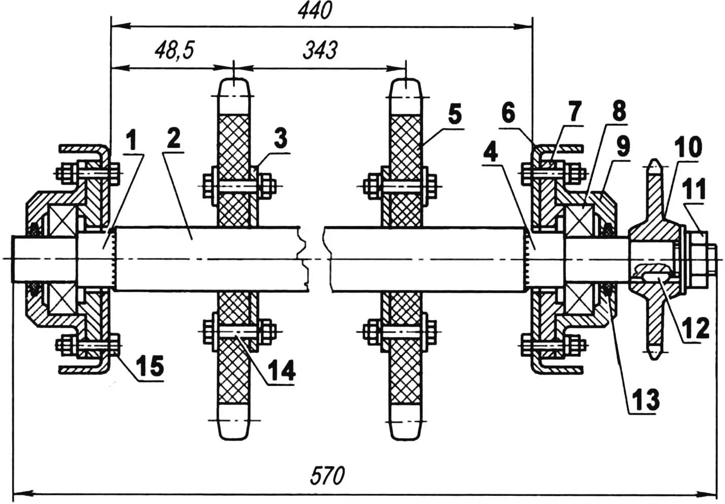
1 — left (in the direction of travel) end piece (steel, circle 22); 2 — shaft (steel, pipe Ø28×2); 3 — flange for fastening the sprocket to the shaft (steel sheet s4, 2 pcs); 4 — right (in the direction of travel) end piece (steel, circle 29); 5 — track drive sprocket (2 pcs); 6 — frame longitudinal member (2 pcs); 7 — bearing housing cover (steel, 2 pcs); 8 — bearing 80204 (2 pcs); 9 — bearing housing body (steel); 10 — shaft drive sprocket; 11 — sprocket fastening on the shaft (M12 nut with enlarged and spring washers); 12 — key (steel 20); 13 — sealing (felt, 2 pcs); 14 — fastening the sprocket to the shaft flange (M8 bolt with enlarged and spring washer, 8 pcs); 15 — fastening the bearing housing body to the frame longitudinal member (M6 bolt with spring washer, 4 pcs)
The track tension shaft is exactly the same as the drive one, only both of its end pieces are identical (like the left end piece of the drive shaft — without the keyway and without threading). However, I call it a shaft only due to similarity; by function, it’s an axle, because no torque is transmitted through this element.
Power unit — a gasoline engine from the “Ural” chainsaw together with its frame is mounted on the engine stand (the fuel tank is also hung on it at the top), welded to the transverse beam. The chainsaw gearbox is turned by 180° and fixed on a platform on which the “speed reducer” (“walk/slowdown” unit, as we call the intermediate shaft among local amateur builders) of the two-stage chain transmission is also installed — and it is precisely this that makes up the whole transmission. The driven sprocket of the 1st stage (the large sprocket of the intermediate shaft) has 38 teeth, and the driving sprocket of the 2nd stage (the small sprocket of the intermediate shaft) has 10 teeth. The chains of both stages are the same — like on motorcycles “Minsk” or “Voskhod” — with a pitch of 15.875 mm.
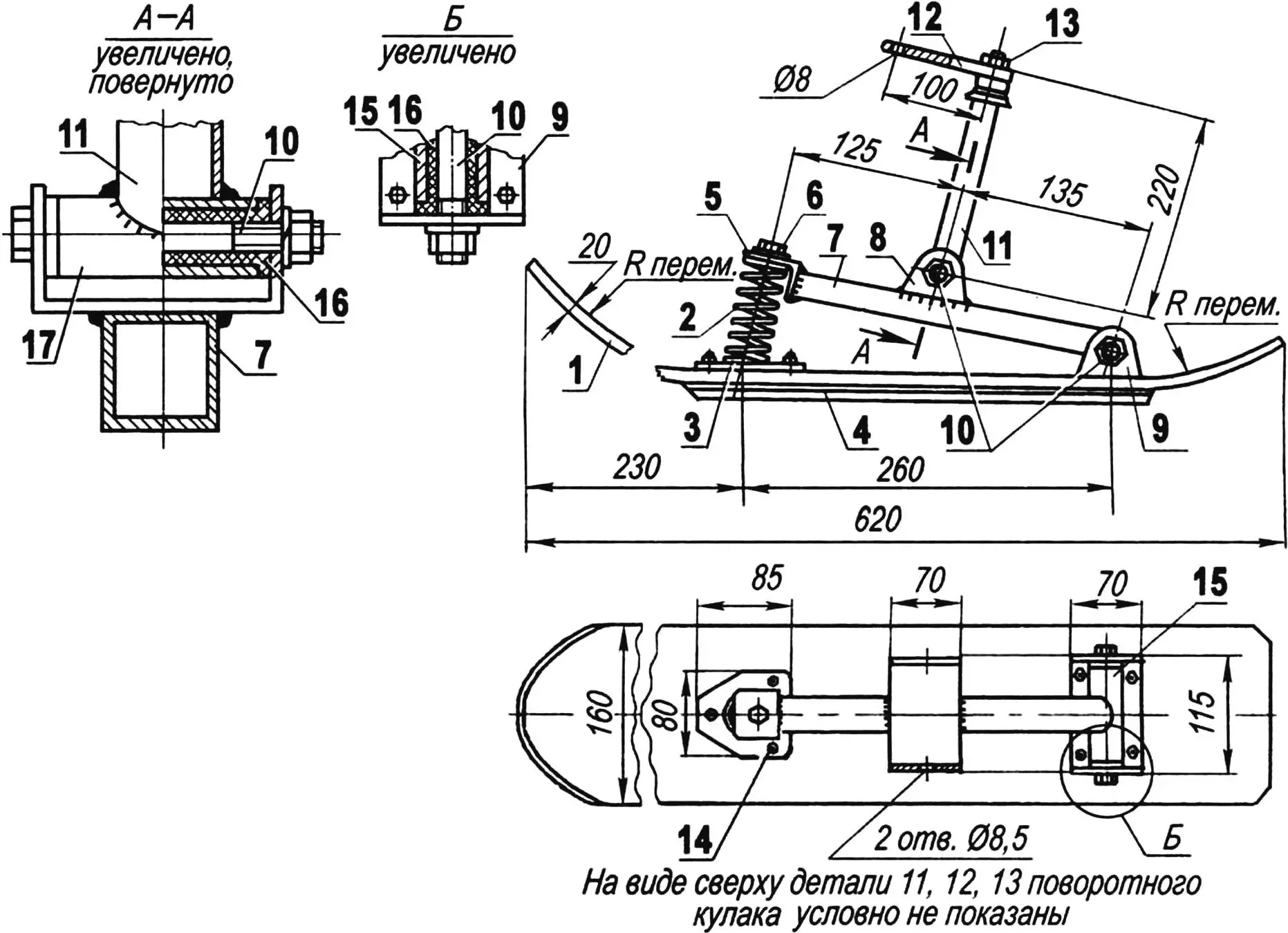
1 — runner (capron sheet s20, from a children’s snow scooter); 2 — spring (normally stretched, from the rear shock absorber of a moped); 3 — spring support / spring pad; 4 — cut / notch (duralumin angle 20×20); 5 — spring cover (angle 35×35); 6 — spring fastening to the cover (M8 bolt with washer); 7 — support lever (pipe 30×30); 8 — eye for fastening the fork stand to the ski lever (steel sheet s2); 9 — eye for fastening the support lever to the ski (steel sheet s2); 10 — axes (M8 bolt, 2 pcs); 11 — steering knuckle stand (bicycle steering column stand with a crown and part of the fork); 12 — steering tie-rod (steel sheet s4); 13 — fastening of the steering tie-rod (M16 nut); 14 — fastening of the spring support pad and the lever eye to the ski (M5 bolt with countersunk head, 7 pcs); 15 — lever bushing (steel pipe Ø30); 16 — sliding bearing (capron bushing, 2 pcs); 17 — stand bushing (steel pipe Ø30)
Steering control consists of support-steering skis, whose levers are connected with rigid rods to the bell crank of the steering shaft — like on a car. The steering wheel itself is of the motorcycle type, two-lever. On it, near the right handle, the throttle control lever is mounted — a twist grip. There are no brakes on the snowmobile — it stops quickly and on its own, thanks to friction in the transmission and the running gear.
The engine power is small (5 hp), but nevertheless the snowmobile reaches a speed of up to 30 km/h on packed snow, and also tows a skier or a sled with a load of 70—80 kg.
At the same time, the snowmobile’s own mass is just a bit more than 40 kg — so it’s better to call it “motonarts”, which is more accurate. Fuel consumption does not exceed 1 liter per 6 km, though usually it’s enough for 8 km. A lot of cargo fits in the box under the seat: there is usually a 5-liter canister with a fuel reserve (the standard tank volume is 2 liters), a tool kit, an axe, and other equipment.
When riding into the forest, for collecting firewood or timber, I carry a saw bar and the gearbox in the trunk — I remove the gasoline motor from the snowmobile and install it on the saw.
The walls of the box under the seat are made of boards “twenties”, and the bottom — from four-layer plywood. The box lid serves as a seat. It is made from 6 mm plywood with several layers of foam rubber covered by a leather substitute. The lid is fastened to the box walls with two “card” hinges and is fixed (latched) with a window latch. The seat lid folds back, and the rear arc then serves as a limiter.
The engine is undemanding and starts quite easily even in a 30-degree frost, so the machine turned out truly wintery. Although it’s risky to ride it in such cold: it’s easy to freeze — because the motonarts are open.
“Modelist-konstruktor” No. 11’2007, A. STARCEV
Recommend to read
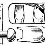 “MUSTACHE” SCREWDRIVER
The main advantage of the Phillips screwdriver slotted in front of the centering tool and fastener, in which virtually eliminates the slipping of the sting with head even with a small...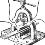 THE CHANNEL FOR FIVE MINUTES!
ROLLING MILL IN THE ROOM?! Is it possible? We are accustomed to the fact that the machine with such name in size comparable to the multi-storey house. And then the baby, a free fit on...
