The desire to build a house came to me at the same time as receiving, in the mid-1980s, a plot of land — the cherished six hundred square meters.
The question of what kind of house to build — brick or wooden — caused no problems. Brick and concrete walls had already tired me in the city. Naturally, the choice fell on wood. Only the question remained open: which type to prefer — log-built (round timber, timber beams) or frame-panel. Everything was decided by chance.
The time for individual developers was not the best — even nails were in short supply.
While looking into the “offers” for sawn timber materials (i.e., simply searching for them), I ended up at one of the construction markets, where a KamAZ truck was loaded, literally up to the roof, with selected boards — “forty” boards, 6 m long. The price suited me, and the driver agreed to deliver the material right to the construction site.
These boards predetermined the construction of the house. And although the project for it was developed later over more than one day, the assumed structural solutions—both for the walls and for the load-bearing elements—were already born there, at the market. In the end, the designed house became a combination of the two timber house construction types mentioned above: log-built and frame-panel.
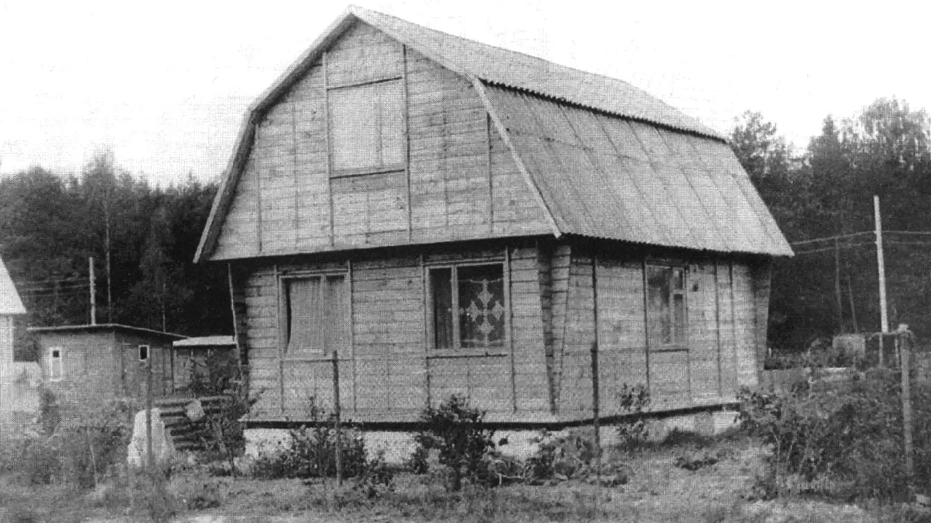
The house architecture is traditional for garden buildings—almost standard, just as required by the dacha construction rules of that time, without any excess.
But I couldn’t keep from adding a little something of my own to the construction—not to stand the house out among its “neighbors”, but so that it would be more convenient to live in.
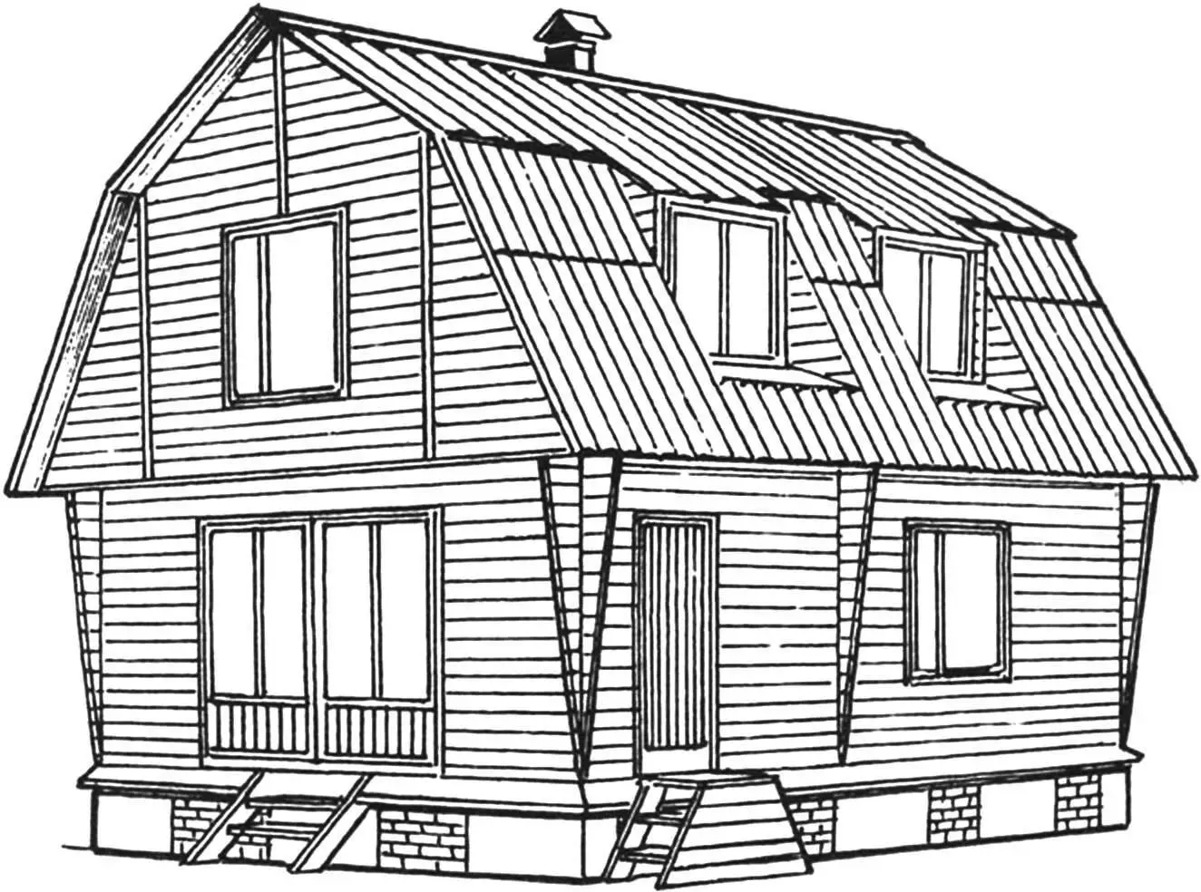
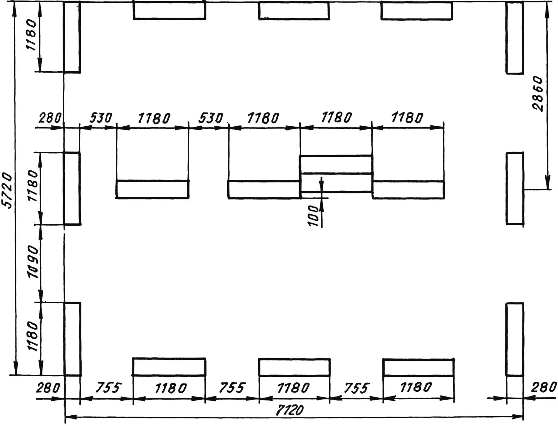
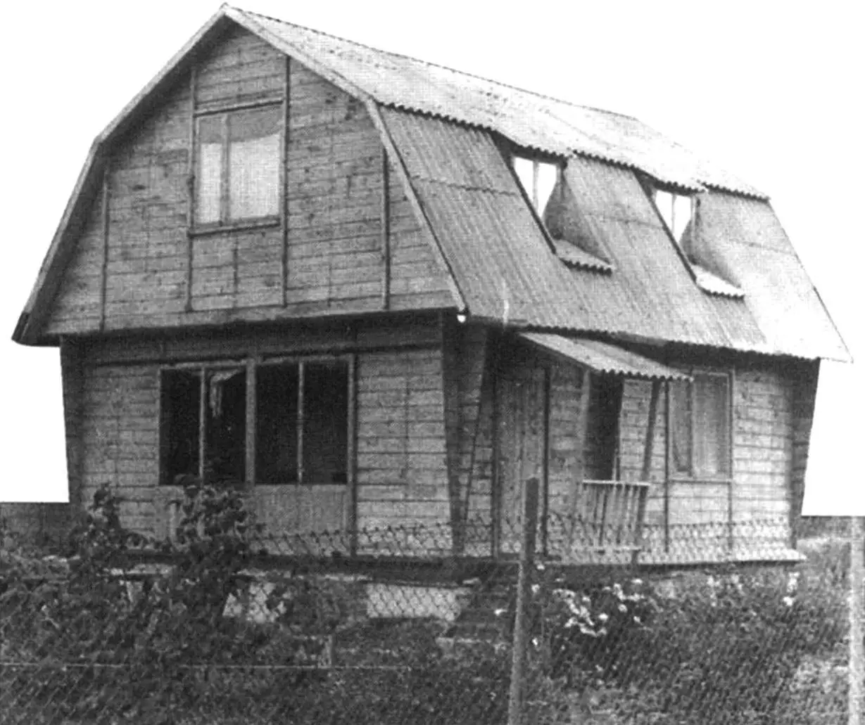
Since the house is one-storey and its dimensions are small (7×5.6 m along the outer walls), to get additional area I designed a mansard. And I increased its “floor area” by means of cantilevered projections of the main floor beams, and its “volume” — due to a “broken” roof. To keep the mansard from looking like an ordinary fitted attic, I made large windows—just like in the house itself. Moreover, not only on the gables, but also, to improve illumination of the upper rooms and the view of the surrounding landscape — on the lower slope of the roof.
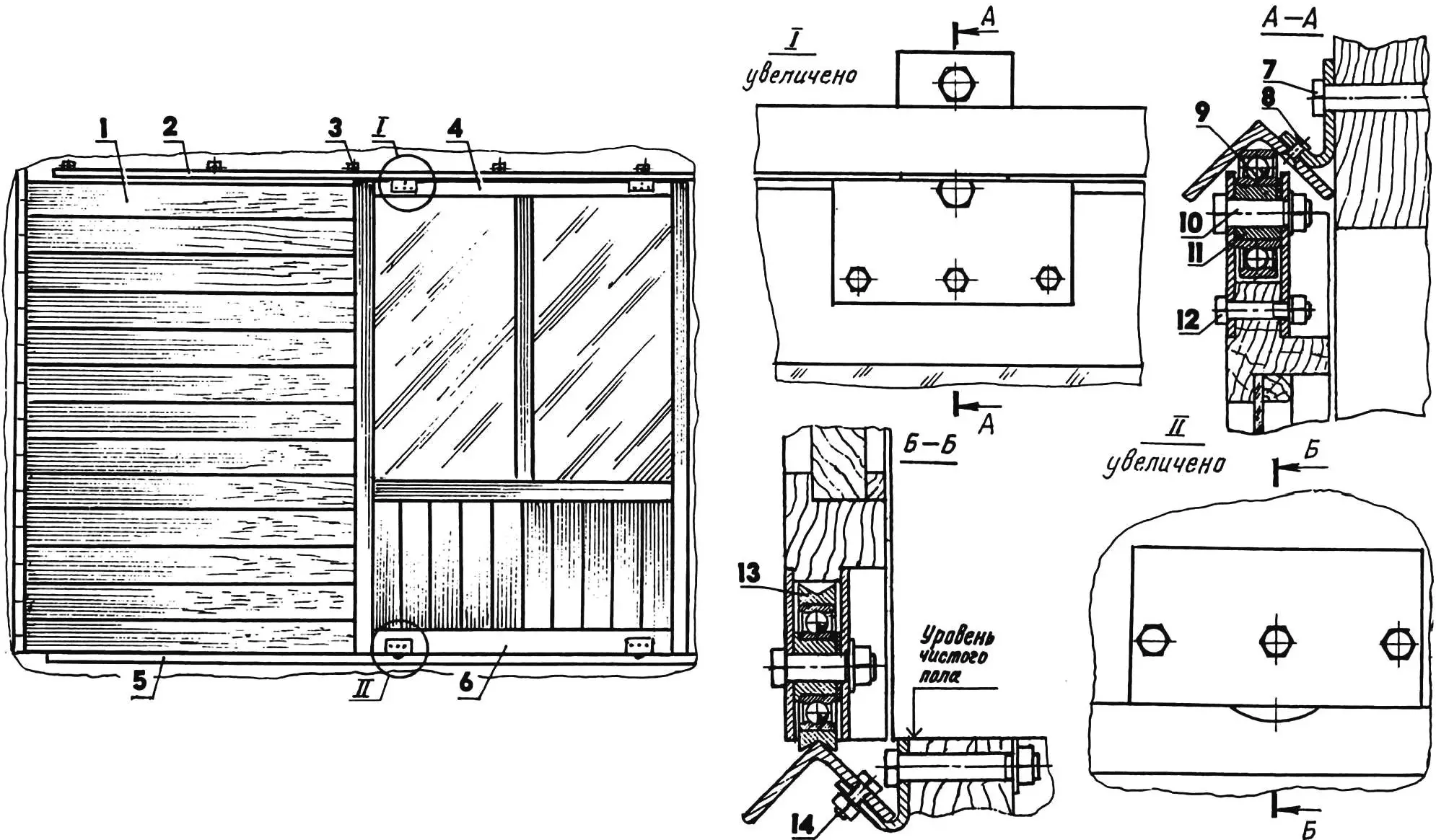
1 — veranda wall; 2 — upper guide (steel angle 40×40); 3 — guide fixing bracket (St3, sheet s3, 20 pcs); 4 — upper door frame (board s40); 5 — lower guide (steel angle 40×40); 6 — lower door frame (board s40); 7 — M10 bolt securing the bracket (20 pcs); 8 — steel rivet with countersunk head Ø4 (10 pcs); 9 — wheel (bearing 80204, 8 pcs); 10 — wheel axle (M10 bolt, 8 pcs); 11 — bushing (St3, Ø25 circle, 8 pcs); 12 — M6 bolt for securing the roller to the door (24 pcs); 13 — wheel bandage (steel 30ХГСА, Ø62 circle, 4 pcs); 14 — M5 bolt for securing the bracket to the lower guide (10 pcs)
But the roof windows didn’t please the officials from the local administration (in their opinion, this went beyond what was allowed), and I was asked to cover them with the roof — which I had to do.
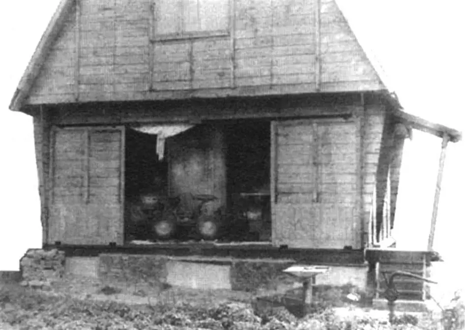
Another feature is the veranda, or rather its wide door-windows. They are sliding, so it is convenient to bring long-length materials through them for interior finishing during construction. Now, however, when the house is built, such door-windows allow you to turn a closed veranda into an open terrace in just a few seconds.
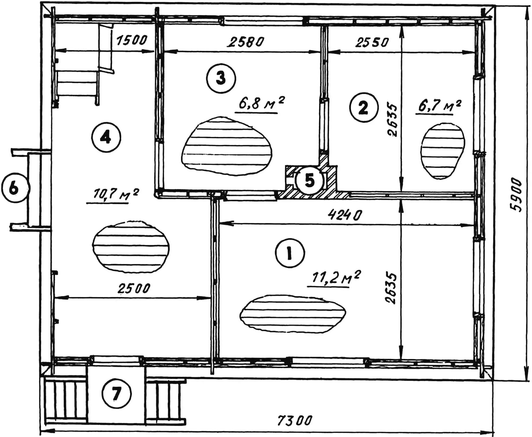
1 — living room; 2 — bedroom; 3 — kitchen-dining room; 4 — veranda-terrace; 5 — stove; 6 — attached small stair; 7 — porch
The house layout is also traditional, rational. On the first level there is a veranda with a staircase leading to the mansard; a kitchen-dining room, a bedroom, and a living room. In the mansard there are two rest rooms. I designed the stove in the center of the house — one stove can heat all rooms both downstairs and upstairs.
The house foundation. When choosing its type, I relied rather on practical considerations, although I took into account economic aspects as well. The subsoil on the plot is dry loam. Groundwater is at a depth of 2.5 m and deeper. Therefore, I decided to make a shallow foundation. A column foundation is, of course, the most economical, but it is also labor-intensive. So I chose a compromise option — a “semi-strip” foundation made from precast concrete blocks of sizes 1180x580x280 mm (length x height x width), laid on a sand pad. The main conditions are to level the block surfaces in one horizontal plane and ensure squareness of their arrangement in plan. The first condition was ensured with a water level; the second — by checking the positions of the corner blocks by diagonals.
After that, I laid 3 layers of roofing felt on top of the blocks, and on them — strapping made of boards with a 150×40 mm cross-section.
The house walls are not quite ordinary. Although the idea of their structure came to me like an inspiration when I bought the lumber, I still had to think through some features of its nodes and details. Combining the log-built and frame-panel types in a single structure has its positive sides. The wall cladding of the house — both exterior and interior — was designed to be self-supporting, as in log cabins. And although the boards are fastened to the frame posts, they do not create loads; rather, this part takes on some of the loads from the structures located above.
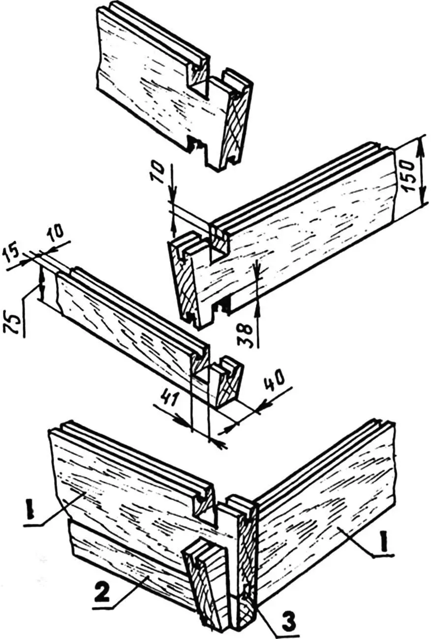
1 — regular board (150×40); 2 — lower (narrow) board of the gable wall (75×40); 3 — spline (rail 20×10)
Visually, the house walls resemble log-built corners “in a bowl with a remainder” (overhang). The “remainders” are also non-standard — if in the lower crown they are quite small, then as you go from crown to crown, in the upper row they become 350 mm overhangs under the gables and more than 600 mm cantilevers under the roof eaves.
The voids between the exterior and interior wall claddings are filled with thermal insulation material — construction foam.
The distance between the inner and outer claddings depends on the insulation available, so that the required thermal resistance is ensured.
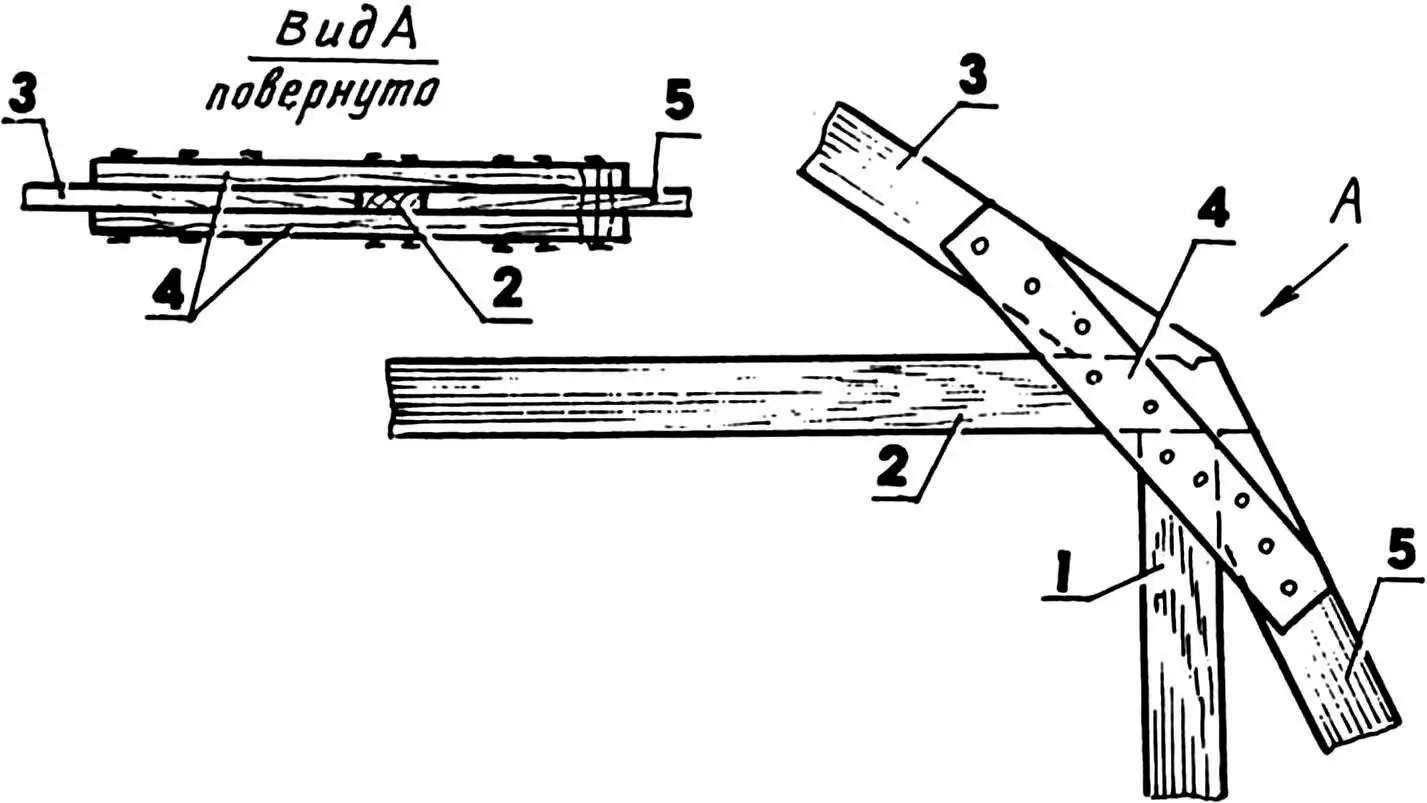
1 — post; 2 — tie beam; 3 — upper knee of the rafter leg; 4 — overlay (2 pcs); 5 — lower knee of the rafter leg
Long warped boards of the cladding were cut into segments of predetermined length and joined during installation on the posts. Outside, the joints are covered with vertical battens.
Inside, the walls are finished with “enhanced” hardboard with a film “like wood”.
Floor beams and beams (also floor joists) are made from boards with the same 150×40 mm cross-section.
1 — foundation block; 2 — waterproofing; 3 — lower (narrow) board; 4 — spline; 5 — regular board of the exterior cladding; 6 — post; 7 — board of the interior cladding (150×20); 8 — joist (board 150×40); 9 — black floor board (150×20); 10 — skull strip (30×20); 11 — lower strapping board
The house roof is mansard, or, as it is also called, “broken”; it has two slope angles: upper slopes — about 50 degrees, lower slopes — about 30 degrees. Accordingly, each rafter leg is made of two knees. The knees are joined in one node together with the posts and tie beams of the mansard frame. At the bottom, the rafter legs rest on the floor beams, and at the top they connect by an overlapping joint. The rafter members are also made of “forty” boards. After assembling the first (gable) rafter form, I used it as a template to make the rest. All rafters are combined into a single spatial structure using the ridge beam and boards of continuous sheathing made from “twenty” boards. The sheathing is continuous to provide additional thermal insulation. Along the top of the sheathing there is wind protection made from roofing felt, and on it — a slate roofing.
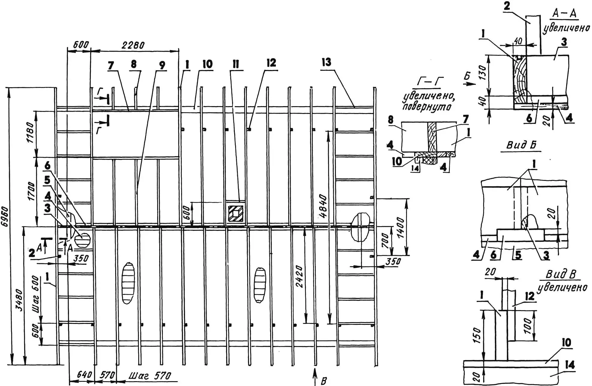
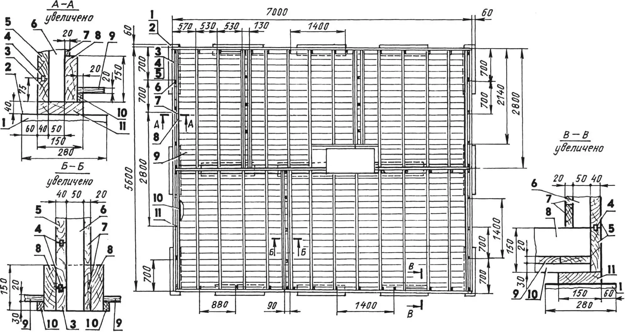
1 — beam (25 pcs); 2 — window jamb (bar 40×40, 4 pcs); 3 — rib; 4 — ceiling boards (150×20), shown conditionally; 5 — upper frame of the gable wall (2 pcs); 6 — ledger; 7 — edging of the stair opening (2 pcs); 8 — console of the side overhang of the opening (3 pcs); 9 — short beam of the opening (3 pcs); 10 — upper frame of the side wall (2 pcs); 11 — edging of the stove opening; 12 — post of the mansard wall (bar 40×40, 23 pcs); 13 — console of the gable (20 pcs); 14 — side wall
The mansard is a special space, especially in a dacha house; its room must be thermally insulated not only on the sides, but also from above. And not so much from cold as from the sun. I used construction foam 50 mm thick as the insulation material. I also used it for sound absorption by laying it into the overlap between the ceiling of the main floor and the floor of the upper level. As for insulating the floor of the lower level, I arranged it from ordinary shavings that I had plenty of after planing the boards. Mixing them with lime putty (lime powder), I laid it between the floor joists over the black floor and covered it with “forty” boards for the finished floor.
The veranda was left uninsulated, because this is still a summer space, and in practice it is mainly used as an open terrace.
The staircase to the mansard is mounted in the corner of the veranda. Perhaps the transition from one level to another in cold weather is not very pleasant, since this part of the house is not heated, but it saves area in the rooms. For safety, the staircase is designed with an offset — a short lower flight and an intermediate landing. The main flight is installed perpendicular to the lower one (in plan), or more precisely at an angle of about 100 degrees. Such a non-standard turn happened because the main flight, with increasing height, moves away from the wall. This is done for convenience so that the roof slope does not interfere with climbing to the mansard. For the same purpose, in the ceiling I cut not a hatch, but a fairly large opening. The staircase parts are made mainly from the same “forty” boards as the exterior wall cladding.
The front porch is an attached one, with steps on two opposite sides. A canopy was mounted above it, supported by slanted posts. The slope of these posts is the same as the slope of the “remainders”/overhangs of the wall releases.
There is also an attached porch-trapik, standing under the sliding window-doors of the veranda.
This “large-scale construction assembly” was completed, but work on landscaping and finishing the house continued. But that is already another topic. I hope that at least something from my experience will be useful for those who build their own house themselves.
“Modelist-Konstruktor” No. 7’2004, E. EVSIKOV
Recommend to read
 “MOSQUITO” WITH FEATHERS
Among purchase toys that can move (ride, swim, run, fly, crawl), it is not easy to find such models that can be safely run in the apartment without fear that they'll break, dropping to... Austin Mini Countryman
Runabout created in 1957, little known at the time to a wide audience by engineer Alec Issigonis of the British Motor Corporation, justly called a masterpiece of design and...
