All-terrain vehicles are my long-standing and enduring passion. For over thirty years now, in my free time, I have been designing and building various all-terrain vehicles. But I have a special passion for snowmobiles: motor skids and snowmobiles, although even among them I give preference to the latter. Probably because he himself once graduated from MAI (Moscow Aviation Institute) and worked at Sukhoi’s company. Snowmobiles and airplanes, as is known, have similar power plants – propeller-driven ones.
I started by creating a tool and machine base. At the request of the editors of the magazine “Modelist-Constructor”, back in the 1980s, the house management allocated me a room in the basement, which I equipped as a small workshop and began to work. Volunteer helpers immediately appeared – guys from our and neighboring houses. I tried to develop their interest in technical creativity, and I think I succeeded. Subsequently, almost all of them connected their lives with aviation, many graduated from the aviation institute and successfully work in design bureaus and aircraft manufacturing companies.
I remember how difficult it was for the first snowmobile – due to the lack of experience in creating such machines. There was no special literature then. Thanks to the magazine “Modelist-Konstruktor”, which I have been subscribing for a long time, or rather since its very appearance in the mid-1960s. Even then, I found a lot of useful information in it, and not only regarding snowmobiles, but also other equipment.
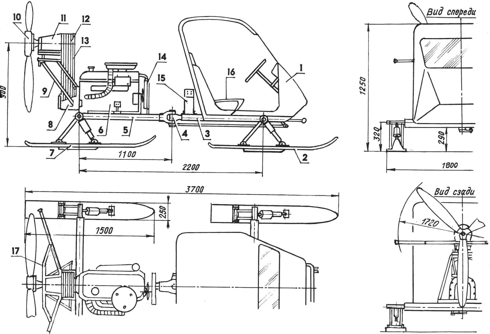
1 — cabin; 2 — front ski (2 pcs.); 3 — front half frame; 4 — articulating unit; 5 — rear semi-frame; 6 — VAZ-2103 engine, N = 71 hp, n = 5500 rpm; 7 — rear ski (2 pcs.); 8 — driving six-groove V-belt drive pulley in the crankcase from the VAZ-2103 clutch; 9 — subframe of the propeller unit; 10 — three-bladed pusher propeller Ø1720 mm with variable pitch from 700 to 1100 mm; 11 — bearing assembly of the screw in the housing; 12 — driven six-ribbed V-belt pulley; 13 — V-belt drive belts (type A, 6 pcs.); 14 — liquid cooling radiator (VAZ-2103); 15 — battery (car); 16 — seat (2 pcs.); 17 — propeller guard (steel pipe Ø22)
I spent two years of free time and hard work on that snowmobile. But even the first pancake did not turn out to be lumpy – a working machine was created.
The snowmobile had a closed two-seater cabin. All four skis were controllable, and therefore the rear ones followed strictly the track of the front ones, significantly reducing movement resistance compared to the three-track (three-ski) pattern.
The engine is from a heavy motorcycle M-72: 2-cylinder, opposed, air-cooled, 22 hp. The propeller is two-blade with a diameter of 1250 mm. With such a power plant, the snowmobile accelerated to 50 km/h.
Luck, as you know, gives you wings. Therefore, there was a desire to make a design with improved driving performance. It became the so-called “air ski” – a snowmobile with one large central ski and two small side (supporting) skis. Control was carried out by two profiled knives installed on the sides of the central ski and extended below its sole. The “airski” with its same propeller-mounted engine was already developing 70 km/h.
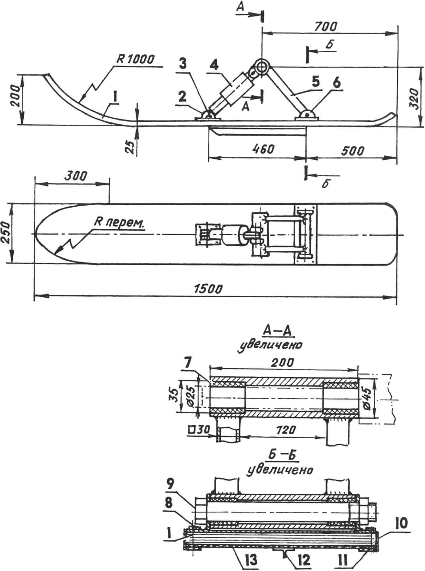
1 – ski; 2 — shock absorber mounting bracket; 3 — axis of fastening of the shock absorber to the bracket; 4 – shock absorber; 5 — lever; 6 — bracket for fastening the lever axis (2 pcs.); 7 — plain bearings of the upper bushing of the lever (textolite, 4 pcs.); 8 — M6 bolt for fastening brackets with a countersunk head (8 pcs.); 9 — lever axis (M10 bolt); 10 — edging (duralumin corner 25×25, 2 pcs.); 11 — screw for fastening the edging (as needed); 12 — undercut (duralumin brand 40×20); 13 — lining (low-density polyethylene, s4)
However, the “old disease” remained – the low-power air-cooled engine, even with such a lightweight design and at a fairly high speed, still overheated even in fairly frosty conditions.
The problem was solved with the acquisition and installation of a decommissioned (but restored) Walter-Minor 4-SH aircraft engine, made in Czechoslovakia, on the “aeroski”. The engine power of more than a hundred horsepower was now enough to tow a hang glider.
No matter how good the “Walter” was, its exhausted resource and difficulties in acquiring spare parts for it posed the next task – to make a snowmobile with an affordable, sufficiently powerful and reliable liquid-cooled engine.
From publications in “Model Designer” on the history of the creation of snowmobiles, I knew about the successful use of automobile engines on them. Back in the war year of 1941, the RF-8 combat snowmobile with the GAZ-M-1 engine was designed and mass-produced. Modern automobile engines have gone far ahead in terms of reliability and power density. The Zhiguli engine 2103 was seen as the most suitable for snowmobiles – it has proven itself to be the best among motorists.
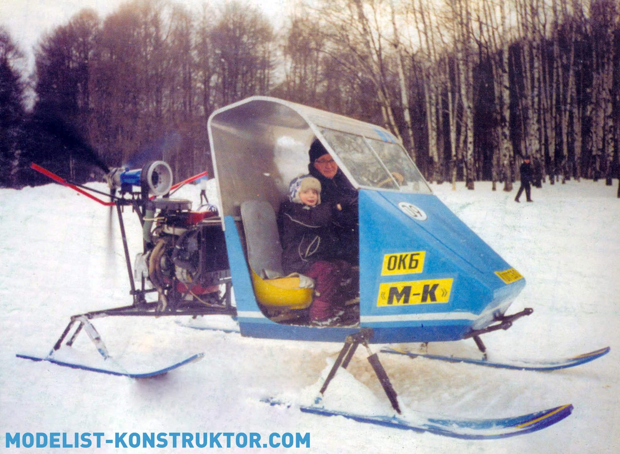
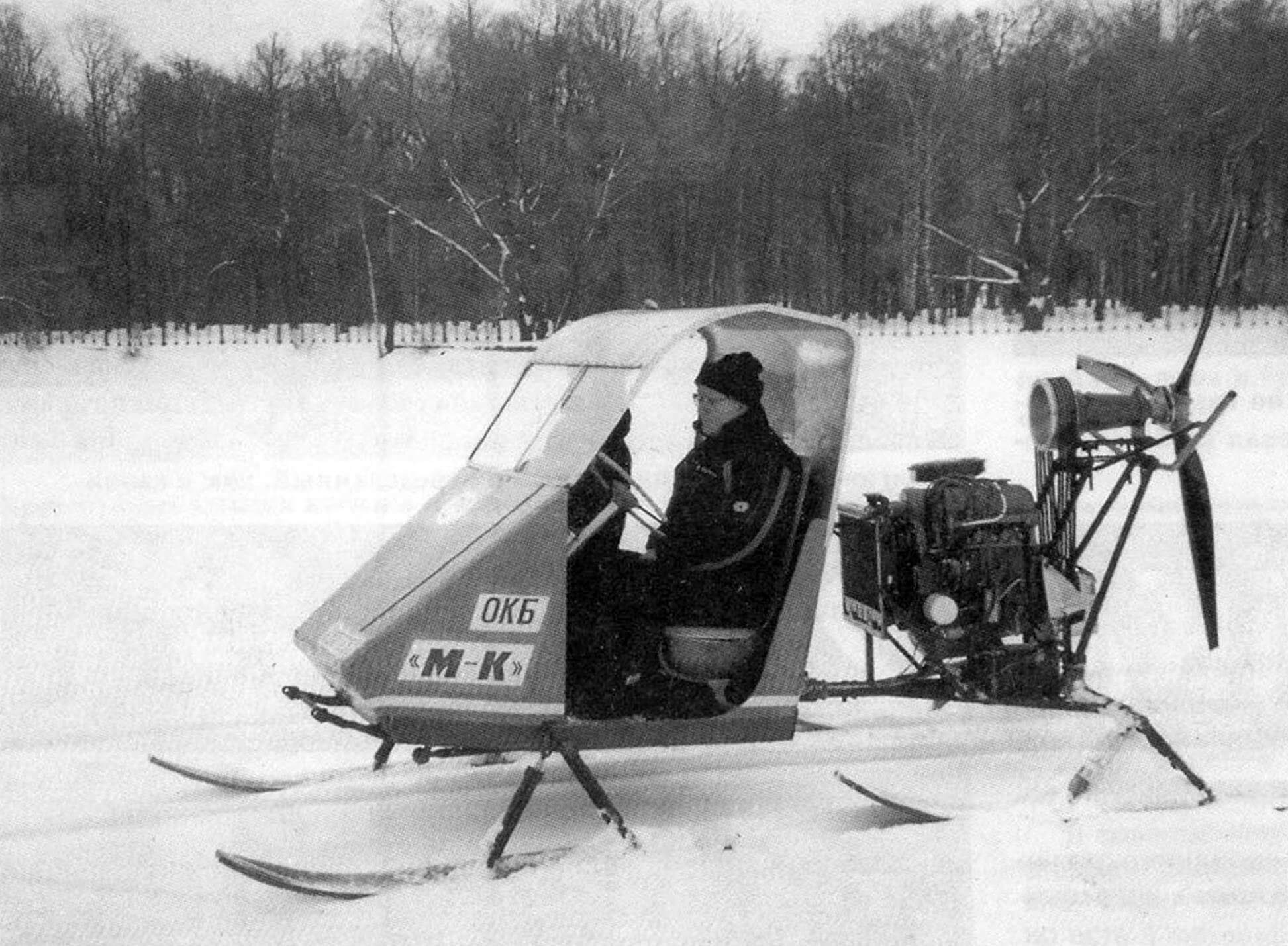
They decided to make the next snowmobile model (already with the next generation of home-made workers – with their son) with the above-mentioned VAZ-2103 engine according to the classic four-ski design, but with a “breakable” frame.
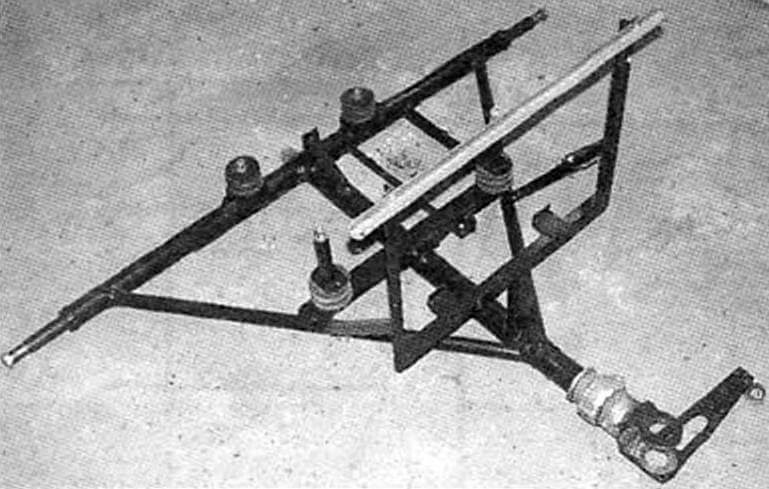
The frame of the snowmobile, although unusual for such machines, is quite simple in design, primarily because it is flat. It consists of two similar T-shaped semi-frames: front and rear. The cab is mounted at the front, and the power unit is mounted at the rear. The cabin has its own frame, and the propeller unit is designed on its own subframe. Thanks to this, both the cabin and the engine can be mounted on semi-frames as autonomous modules.
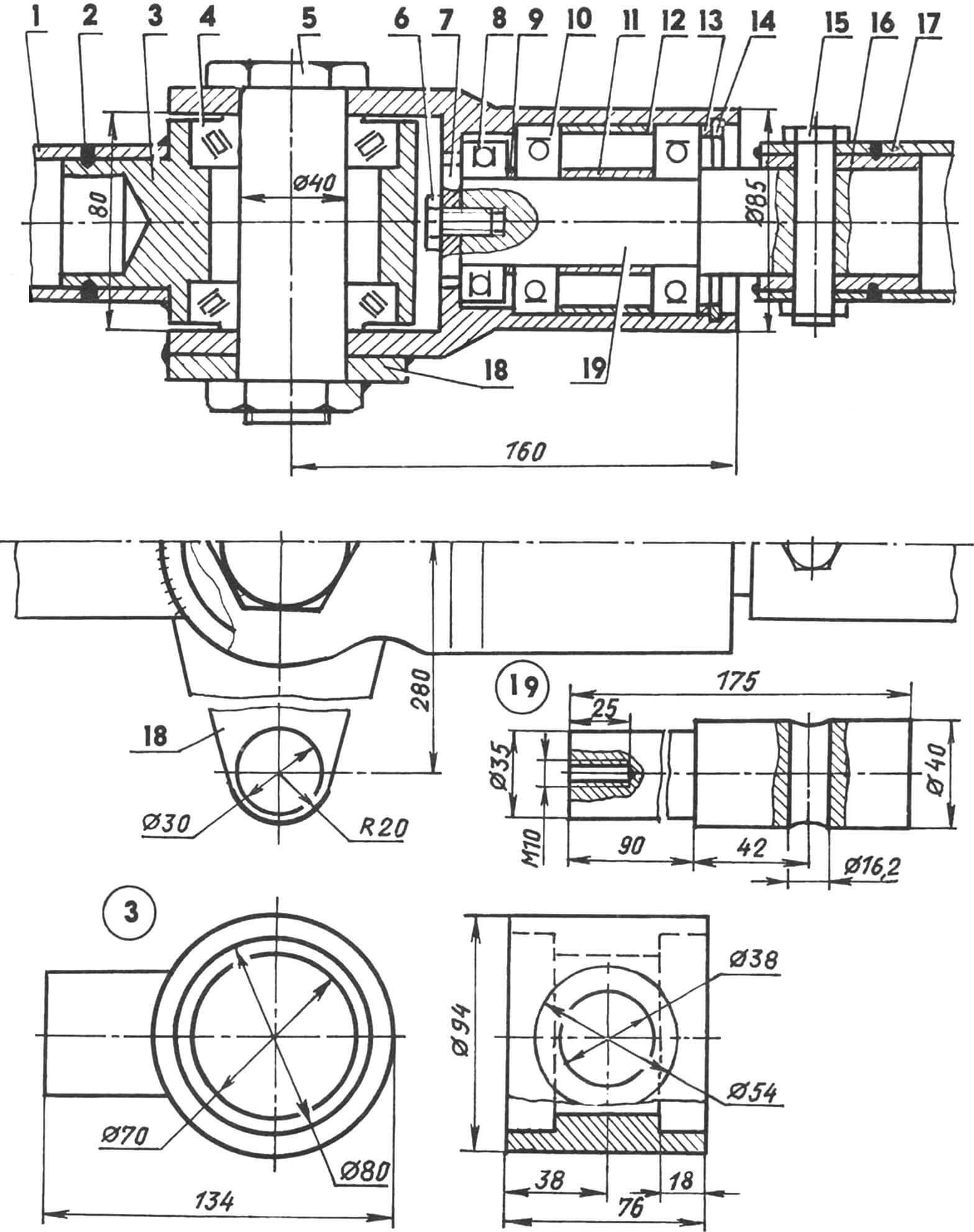
1 — front frame spar; 2 — “electric rivet” (as needed); 3 — hinge bushing (St3); 4 — angular contact roller bearing 7208 (2 pcs.); 5 — hinge axis (special bolt Ø40 and M36); 6 — axial bolt M10; 7 — axle travel limiter (St3, sheet s8); 8 — thrust ball bearing 8207; 9 — short spacer sleeve (St3, circle 41); 10 — radial ball bearing 180207 (2 pcs.); 11 — internal spacer sleeve (St3, circle 41); 12 — external spacer sleeve (St3, circle 72); 13 — adjusting washer (St3, circle 72); 14 — retaining ring; 15 — cotter pin (M16 bolt); 16 — filling sleeve (St3, circle 72); 17 — rear frame spar; 18 — rocking lever; 19 — axis of rotation of the rear semi-frame (steel 45, circle 40)
The basis of each half-frame is a central spar and traverse, made of thick-walled steel pipe with a diameter of 60 mm. At the free ends of the side members, mating parts of the hinge joint are mounted, thanks to which the frame can “break” at an angle of 60° – 30° in either direction, thereby carrying out a corresponding rotation of the machine or a turn. The T-shaped connections of the side members with the traverses are reinforced with struts. In addition, additional elements are welded to the semi-frames, which do not particularly affect its rigidity and strength, but are necessary for mounting the cabin and propeller unit on them. And further. To relieve the frame from twisting moments and prevent skis from hanging over uneven roads, the rear half-frame has the ability to rotate relative to the longitudinal axis. For this purpose, a bearing unit is provided in the hinge.
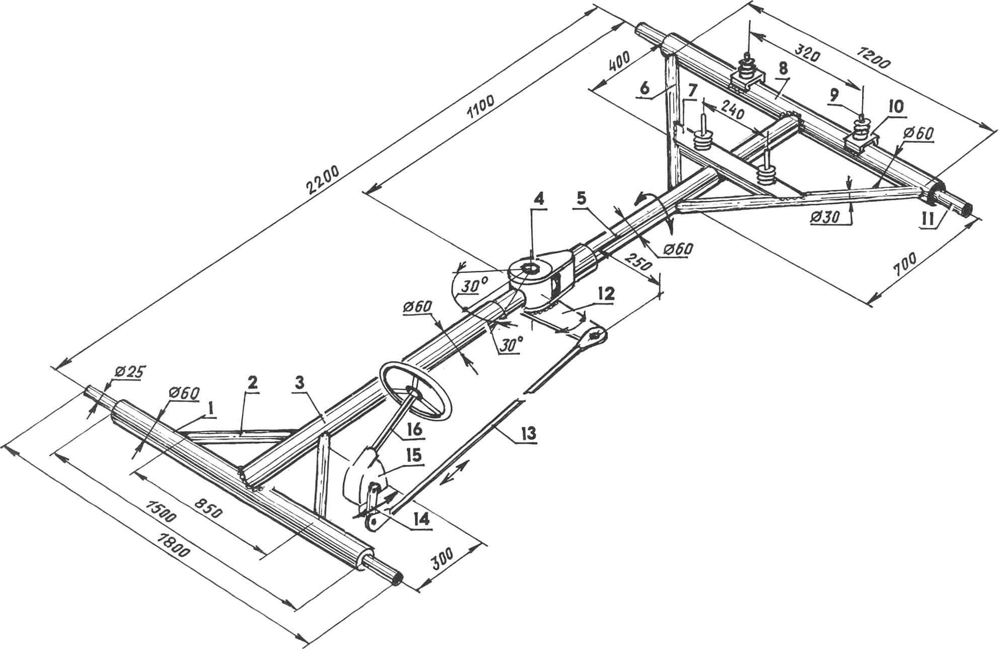
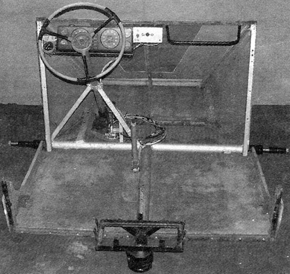
1 — traverse of the front half-frame (pipe Ø60); 2 — strut of the front half-frame (pipe Ø30, 2 pcs.); 3 — front frame spar (pipe Ø60); 4 — hinged connecting point of the front and rear semi-frames; 5 — rear frame spar (pipe Ø60); 6 — strut of the rear semi-frame (pipe Ø30, 2 pcs.); 7 — cross member (channel No. 5); 8 — rear half-frame traverse; 9 — M12 threaded pin with a rubber engine mount; 10 — support platform (channel No. 5, 4 pcs.); 11 — ski suspension axis (pipe Ø25, 4 pcs.); 12 — rocking lever for “fracture” of the semi-frames; 13 — rod (pipe Ø22); 14 – bipod; 15 — worm steering gear; 16 — steering shaft with steering wheel
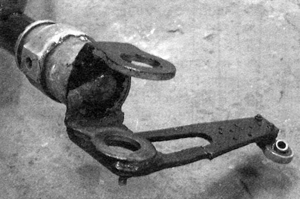
The photograph of the hinge assembly and its drawing have non-fundamental differences – these are possible design options.
During the installation of the snowmobile, a battery platform was also welded to the spar of the front half-frame, and a stand for mounting the radiator was welded to the rear half-frame. But these elements are not power and are not included in the frame drawing – they are clearly visible in the photographs.
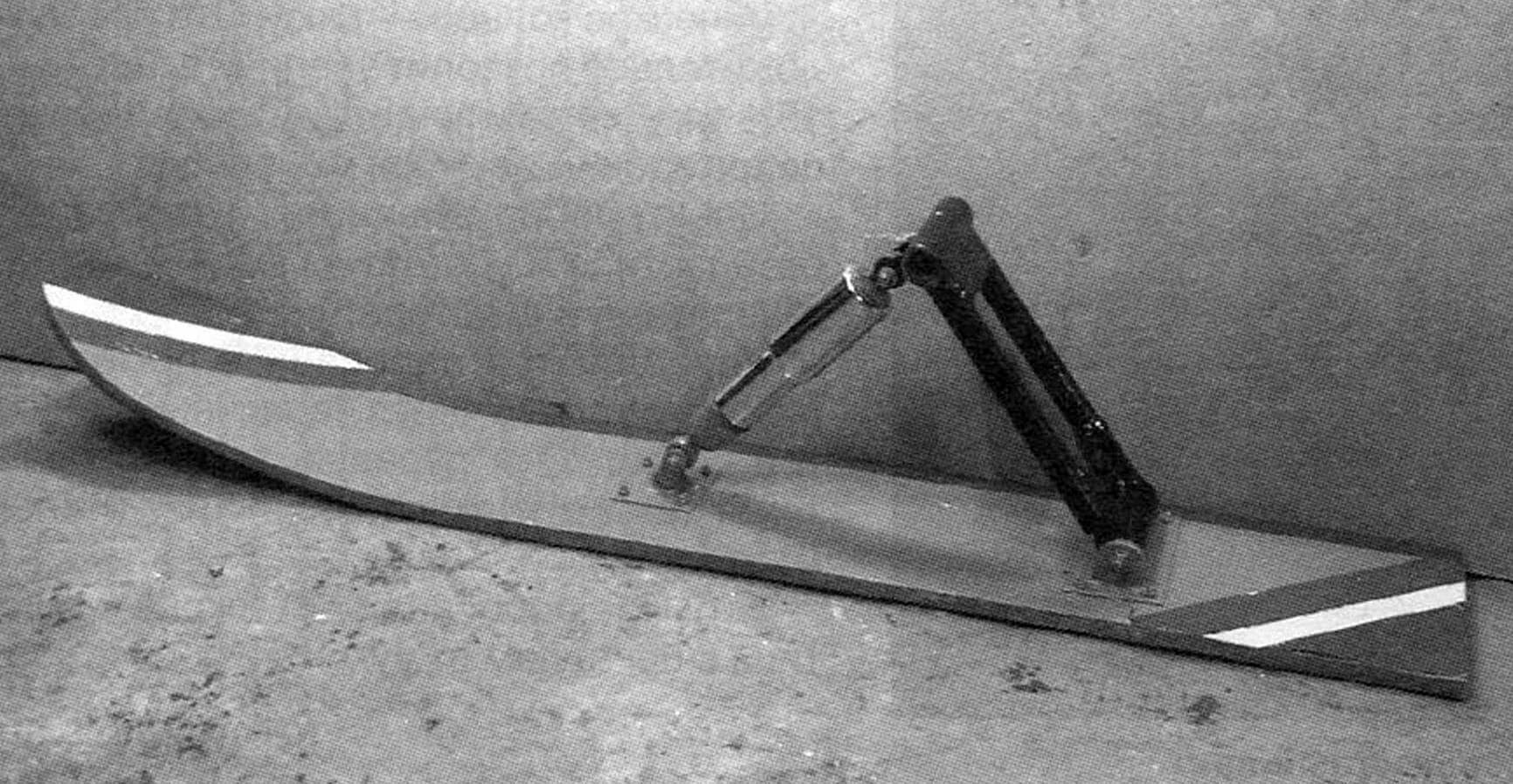
The design of the snowmobile undercarriage is ski, four-legged, two-track. All four skis are the same. Glued from five layers of 4 mm plywood with epoxy glue. The soles of the skis are lined with low-density polyethylene 4 mm thick. In the middle of the ski there are undercuts made of duralumin brand, and along the edges there are edgings from the same corner 25×25 mm. The suspension arms are welded from pipes: the struts are made from square ones (30×30 mm), and the bushings are made from round ones with a diameter of 45 mm. Each ski suspension is equipped with a spring-hydraulic shock absorber from a heavy Ural motorcycle. The ski is suspended from the upper bushing of the lever on the frame axis.
The snowmobile’s cabin is two-seater, the driver and passenger seats are located next to each other. The cabin frame is assembled from duralumin pipes with a diameter of 16 mm. The sheathing and floor are plywood. The front windshield is from an SZD motorized stroller. The cabin is attached to the front half-frame at four points through rubber shock-absorbing pads.
The main module of the snowmobile – the propeller-motor unit – consists of an engine, a V-belt drive and a propeller.
The engine, as noted earlier, was used from the Zhiguli-2103 car without modifications. The clutch housing and even the end part of the gearbox were taken from the same car. But in place of the clutch basket, a six-groove V-belt drive pulley is now installed (gear ratio i = 2). The belts are of type A profile. A window is cut out for them in the upper part of the crankcase. And in order to maintain the strength of the crankcase, its rear cover was subsequently pulled to the engine with a lanyard.
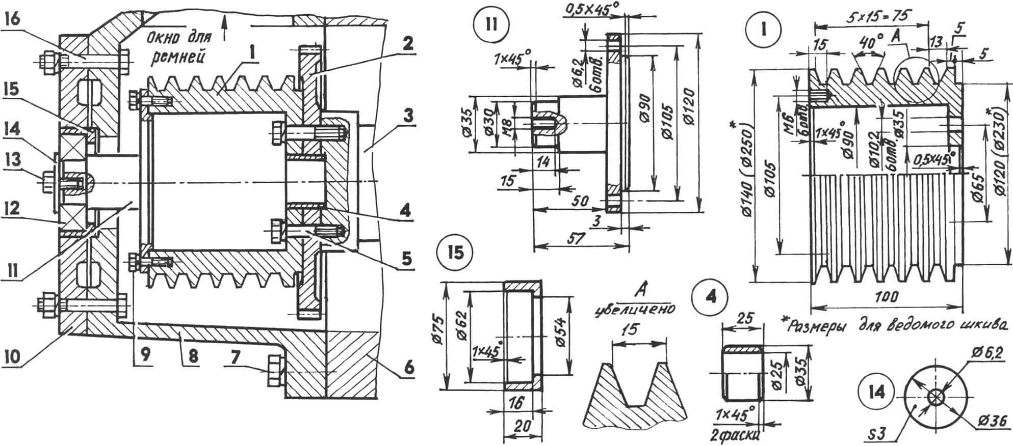
1 — driving six-groove pulley with a groove profile for a type A V-belt (duralumin, circle 140); 2 — engine flywheel; 3 — engine crankshaft; 4 — centering front bushing (St3, circle 35); 5 — M10 screw (with spring washer) securing the drive pulley and flywheel to the crankshaft (6 pcs.); 6 — engine cylinder block; 7 — screw securing the clutch housing to the engine block (standard, 5 pcs.); 8 — clutch housing (modified); 9 — M6 screw with a spring washer for fastening the axle flange to the drive pulley (6 pcs.); 10 — cover (front wall from the VAZ-2103 gearbox); 11 — axle (steel 45, circle 120); 12 — bearing 180506 (62x30x16 — Dхdхb); 13 — M8 screw for fastening the washer-nozzle; 14 — washer-overlay (St3, sheet s3); 15 — centering rear bushing (St3, circle 75); 16 — M10 screw with spring washer securing the cover to the clutch housing (6 pcs.)
The drive pulley is attached to the flywheel and sits with it on the engine output shaft. But to relieve the bearing of the engine output shaft, a short axle with a flange is attached to the pulley from the outside. The end of the axle is installed in bearing 180506. The housing of this bearing is mounted in the end cover of the gearbox.
The driven pulley is located on the same shaft with the propeller, at its opposite end. The shaft itself is installed in two bearings: one (180110) on the pulley side, the other (180508) on the screw side in a single housing.
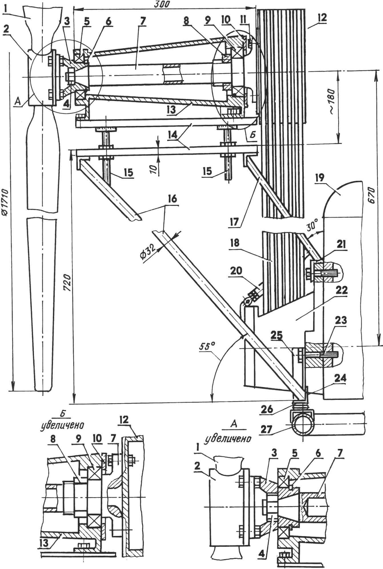
1 – screw; 2 — screw bushing; 3 — small flange of the propeller shaft; 4 — M20 nut for fastening the flange; 5 — bearing 180110; 6 — bearing retaining ring; 7 — propeller shaft; 8 — bearing fastening nut; 9 — bearing 180508; 10 — bearing housing cover; 11 — M10 bolts for fastening the pulley and the large flange of the propeller shaft (6 pcs.); 12 — driven pulley; 13 — bearing housing; 14 – naya and movable platforms; 15 — belt tension adjusting bolts (M16, 4 pcs.); 16 — long strut (steel pipe Ø32, 2 pcs.); 17 — short strut (steel pipe Ø32, 2 pcs.); 18 — drive belts (type A, 6 pcs.); 19 — engine; 20 – lanyard; 21 — support cross member of short struts (angle 60×30); 22 — crankcase with drive pulley; 23 — M10 bolt securing the subframe to the power unit (4 pcs.); 24 — support cross member of long struts (angle 60×30); 25 — rack (corner 40×40, 2 pcs.); 26 – pillow; 27 — cross member of the rear half-frame
To lower the center of gravity of the sled, the engine is placed directly on the frame on four shock-absorbing rubber pads, and the bearing housing with a driven pulley and screw above the engine is located on the platform of a specially made subframe. To tension the belts, the platform rises higher as they are pulled out. Together, the units constitute an autonomous propeller-driven power plant and, if necessary, can be removed from the snowmobile and installed on another vehicle, such as a boat, turning it into a glider.
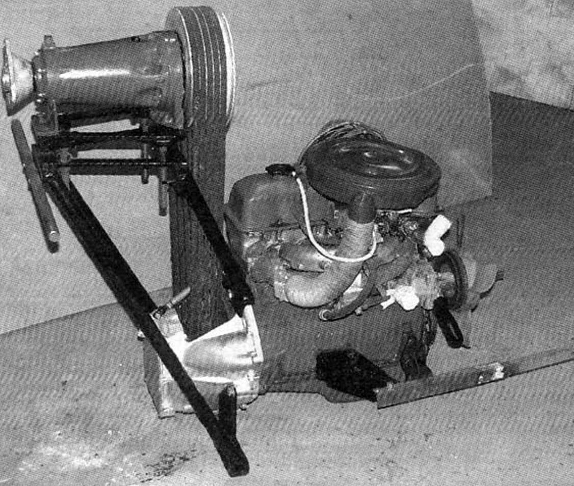
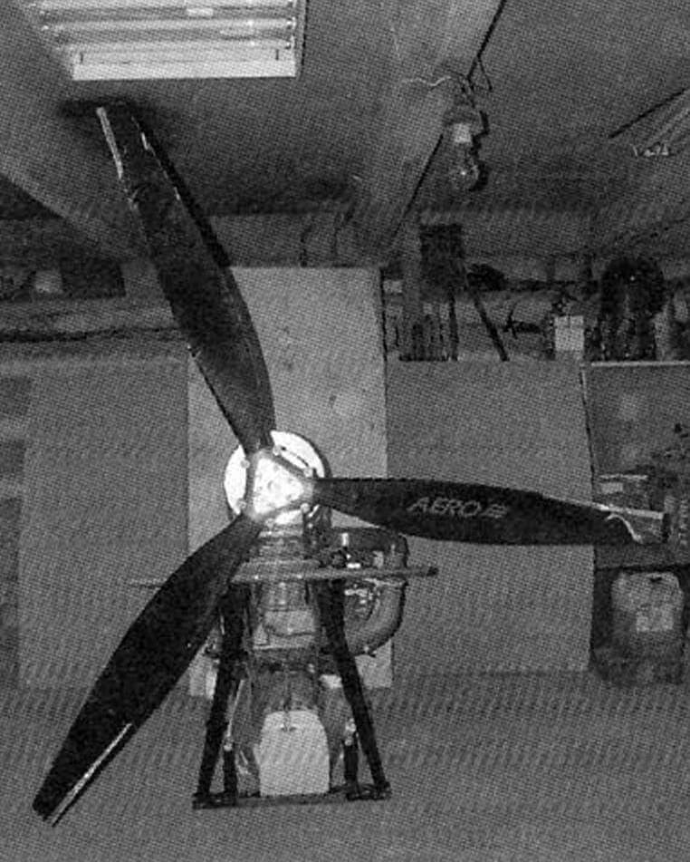
The snowmobile propeller is a pushing three-bladed propeller, fixed (changeable on site) pitch from 700 to 1100 mm, diameter 1710 mm, industrial production. Before this there was a homemade two-bladed one. It still remains from a propeller-driven power plant with an engine from an M-72 motorcycle. But with a VAZ-2103 engine, the propeller worked even worse than with a motorcycle one, and it had to be replaced.
The most important element of the safe operation of a snowmobile is the propeller guard. On my car it is still large and tubular. But in the future I’m thinking of replacing it with an aerodynamic ring – a nozzle. This will presumably increase the propeller thrust by 10 – 15% and protect the propeller from damage by tree branches.
The electrical equipment of the snowmobile is standard and consists of a battery, a generator and a starter.
The snowmobile is controlled using a steering wheel through a worm gear with a bipod and a steering rod, which pulls (or pushes) the rocker and “breaks” the frame.
The snowmobile brake is a scraper type driven by a handle via a cable.
V. KUKIN
Recommend to read
 JAGUAR R-COUPE
The basis of the most famous British car company Jaguar Cars was firm SS Car Company, which in 1945 had to change its name — becauseone SS at that time, no one called benevolent... “ELECTRONIC” CULTIVATOR
The idea of creating a mechanical assistant for garden cultivation came to me a long time ago. I looked through relevant issues of the “Modelist-Constructor” magazine with descriptions of...
