
 Most of the machines and mechanisms used in industry, agriculture and the service sector, by themselves, unfortunately, still not working. These mechanisms have to enable, disable, change their speed and direction of movement, etc., it is necessary to control their work.
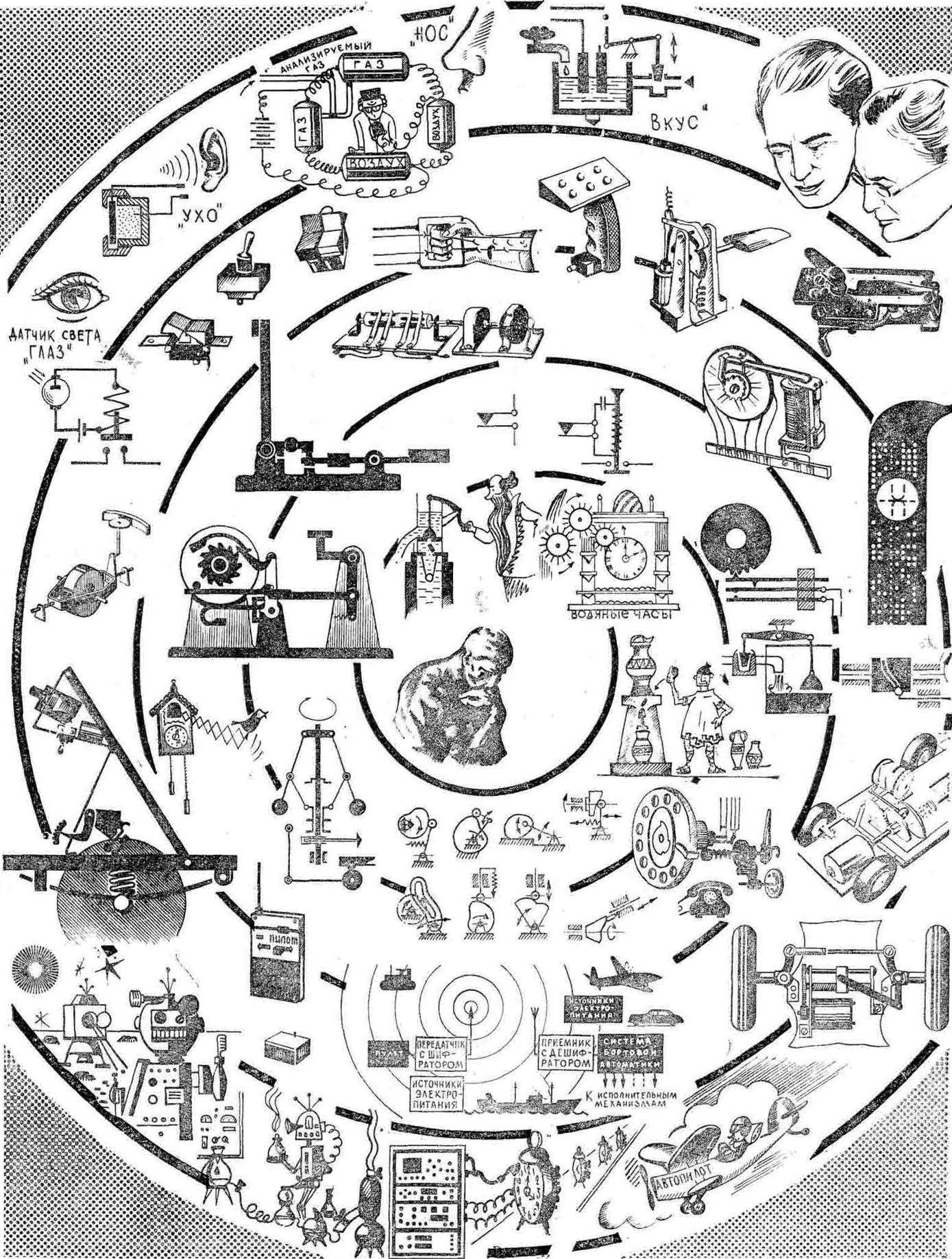
The further develop science and technology, the more man seeks to free himself from the inefficient and heavy physical labor. This kind of work at all a large amount is passed on to the machine. But sometimes the control mechanisms is associated with a hard physically challenging activities; therefore, there were self-driving cars, automatic and semiautomatic, for example, in aviation — “the pilot-robot”, the autopilot, communication — automatic telephone exchange, trade booths and many more “smart” machines (Fig. 1). Increasingly widely used in engineering principles of Cybernetics, bionics, fluidics, remote control. The development of such mechanisms employed large teams of engineers, scientists, as the mechanization and automation of production processes are the basis of scientific and technical progress, they are the powerful base of development of production and the productive forces of our society.
When developing technical devices, we will also try to solve some of the tasks associated with the selection of the optimal principles for the management of these devices.
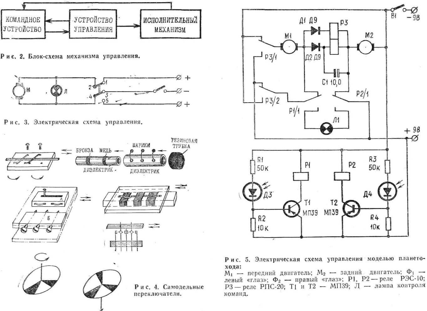
Construct the block diagram of the proposed control mechanism (Fig. 2). First, you need to perform the work of a block diagram, and then outline the principle of operation of the command device.
Consider the possible situation in which you will have to work our cars.
We define the operation of the device working in the school workshops, the idea of which has already been discussed in the journal “modelist-Konstruktor” (No. 9, 1974, p. 47).
The movement of the mechanism in this workshop possible, for example, on such routes:
A — from the teacher’s Desk around the desktops of students;
B — from the teacher’s Desk between the ends of the desktops of students and back to the teacher’s Desk.
What are the advantages and disadvantages of these routes? The advantage of route A is that the movement of the device occurs with a constant speed and in one direction, that is, not changing the direction of rotation of the motor shaft. Its disadvantage is the relatively complicated and long way of movement of the device, and the investigator but, and duration of distribution of blanks, parts, etc. in addition, when the movement of the device along the route And it is impossible to completely eliminate the possibility of collision of the device with the student.
The advantage of route B is, first, a shorter path of movement. While students can take deliver the items simultaneously from two sides, and it provides additional time savings. Second, the motion is direct, safe routes monitored by the teacher and students, and reduces the possibility of occurrence of the emergency situation.
The B route has the disadvantage that the need to change direction half way at 130 degrees.
The conclusion seems clear: choose route B and you make an additional clarification: it is desirable to provide the ability to stop the device from each desktop of the disciples at the command of any of them.
The logic of operation of the device seems tech: the teacher gives the command, the device moves in a straight line, transient between the ends of the desktops of the students, then returned to the teacher’s Desk and stops. If necessary, it is possible to stop any of the desktops (used as a control device is here a teacher or student).
Define the principle of operation of the mechanism control device. Because every transmission of the commands requires an expenditure of energy, you must first choose the source. We agreed that it would be the battery, so it is easier for us to control mechanism to use electricity. To operate our device, it means to command: the motion for a change of direction move and stop. To change the direction of motion of the device is sufficient to cause the motor shaft to rotate in the opposite direction, which is achieved very simply by changing the direction of current through the switch. For the movement or stopping of the device is sufficient to turn on or off electrical power to the engine.
Now our problem is reduced to drawing electrical circuits; its components — a motor, a switch, a switch and a constant current source. To control turn on of the device under the voltage you can use a light bulb with a color filter or the lamp button. One possible electrical control circuits for the device shown in figure 3.
If you don’t have a switch, can produce it yourself. Figure 4 shows several workable designs improvised switches.
Consider the control action of the device on the school grounds (option II). Here the working situation can be very different and very changed often. So to program them impractical. In this case, one of the rational solutions can be considered traffic control devices on all of its route, i.e., directly man. This means that the person is near the device and gives him the command “move” and “stop”. The electrical circuit may be similar to the previous one (see Fig. 3), but the switching is done manually.
When designing a control mechanism model of the lunar Rover also, it is first necessary to clarify a possible situation in which he will have to work. Consider some of them.
I. the Device is delivered in a cargo rocket at some convenient landing point on the planet from which the lunar Rover should make the outputs at certain points or along certain routes to gather different information. According to the team he needs to go back to the rocket.
II. The lunar Rover makes the transportation of cargo from the spacecraft to a stationary base on the planet. At the approach to the base device signals the arrival.
III. Calling the lunar Rover, for example, in an emergency situation. The team from the point of the accident the lunar Rover moves to this point, when you approach it stops and transmits information to the base. If in trouble the astronauts themselves can take to come to them, the lunar Rover, it delivers them to the base or косvический ship depending on the received command.
Now apply this situation to the table and outline the actions that should make the model lunar Rover in charged situations.
Command signals can be fed in any sequence.
Define the principle of operation of the control mechanism of lunar Rover model A. Since the model needs to distinguish the direction command signals, by analogy, for example, with the visual human reaction, you can build management with “eyes” that perceive light signals.
THE SITUATION – ACTION MODEL
I. the Command signal is not, the power is turned on. Model planetary Rover performs a circular movement.
II. The command signal on the left. Model of the lunar Rover makes a left turn while the signal source is not directly ahead.
III. The command signal on the right. Model of the lunar Rover makes a right turn while the signal source is not directly ahead.
IV. Command signal directly ahead. Model of the lunar Rover moves right.
V. Command signal at the exchange rate at a certain (adjustable) distance. Model of the lunar Rover stops and starts the transfer of information: the source of command signals found.
So, let’s examine the control using the “eye” and light. Depending on which side of the signal appears (i.e., is illuminated by a right or left “eye”), triggers the appropriate relay. Power is supplied to the engine, and the rotation in the direction of the light source, after which the movement goes straight to the source signal, that is provided by the situation II; III; IV. If the “eyes” model of lunar Rover “beveling” on the course, when approaching the source of the signal to a specific, pre-set distance, both the “eyes” will be equally illuminated. In this work the appropriate relays that disable power to the engines, and turn signal, indicating that the source of command signals is found (situation V).
If the light source is turned off, the model begins to look for a new source of signals is rotated around the axis (situation I). When signal model will move to it etc.
The sequence of operation can ensure the proposed scheme (Fig. 5).
Offer you to continue the development of technical devices that we have outlined previously (see “modelist-Konstruktor” No. 9, 1974).
LITERATURE
Artobolevsky I. I. Mechanisms in modern technology. M., “Nauka”, 1971.
“Children’s encyclopedia”, vol. 5, Moscow, Prosveschenie, 1965. Dmitrenko A. N. Electronic automation. M., publishing house of DOSAAF, 1973.
Dyakov A.V. RC models. M., publishing house of DOSAAF, 1973. Magazines “modelist-Konstruktor”, “Radio” for 1973, 1974.
(To be continued)
Recommend to read
 FOR STUKELEY SCHEME
The search for new solutions before the next sports season has led our members to very unusual for present-day design. In a subclass of HH-0.2 is now dominated by specialized yacht...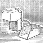 SCOOP IMPROMPTU
A fluid or oil is supplied to market in plastic canisters of different capacities. A worn or leaky thrown into the garbage. However, one can do some useful things — for example,...
