FLYWHEEL ELEVATOR

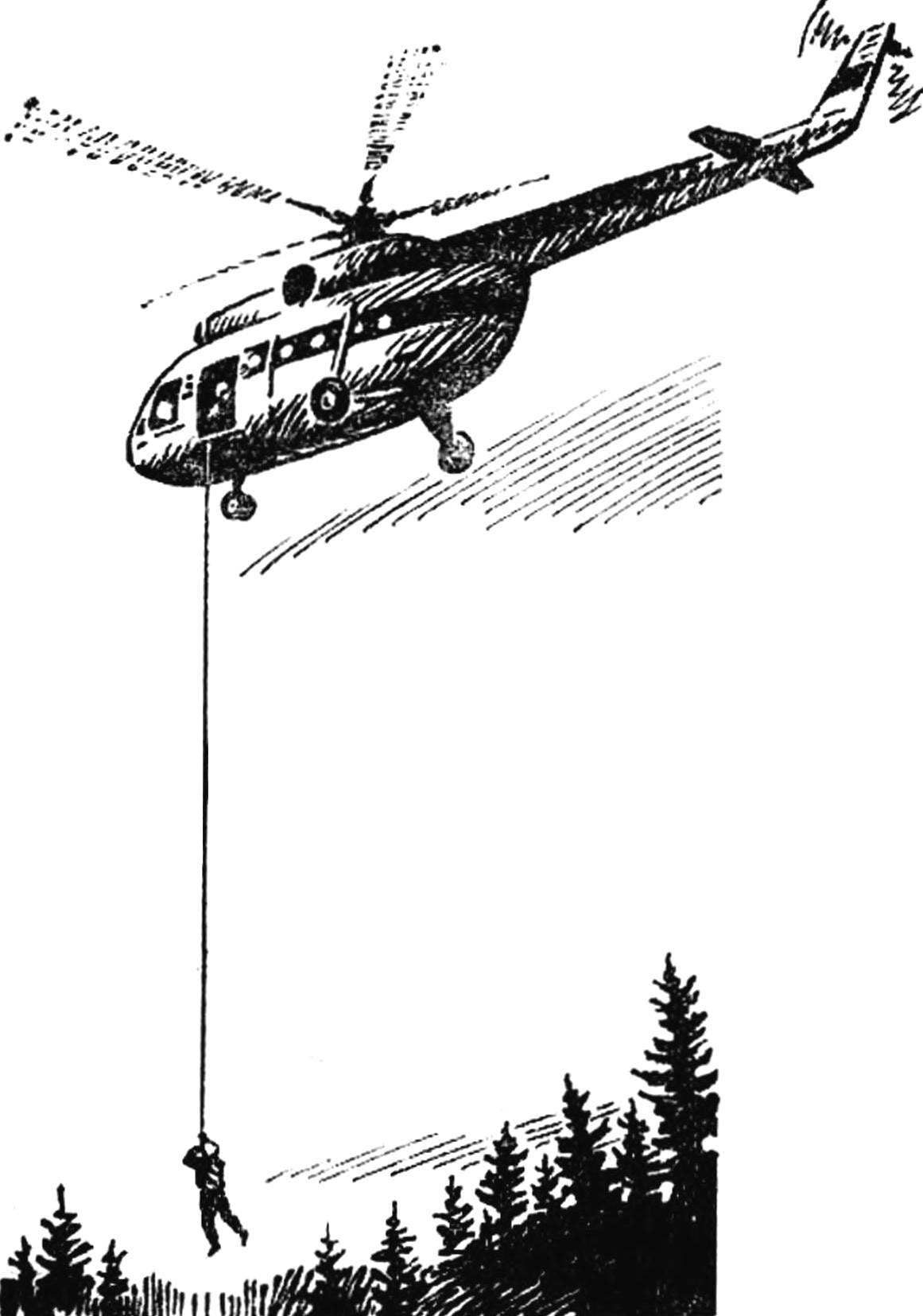
FLYWHEEL ELEVATORIn the halls of the Central exhibition NTTM, dedicated to the XXVI Congress of the CPSU, it is possible to see many original designs and arrangements, created by young scientists, innovators various sectors of the economy. Is on display and very unusual exhibit — a fragment of a brick house, over which a fortified small drum with a wound on its shaft with tape. This flywheel model of lift is designed for lowering people from a height of 100-150 m in the case of fires or other natural disasters, when the regular elevators stopped because of power-cut. The device can be useful when landing fire landing of a helicopter, for example, on forest fires, when landing is impossible because of the smoke.

 
There are many devices for lowering people from a height. For example, the coil cable and the brake bushing to regulate the speed of descent. But they can take advantage of only one person, and that the decline will be very slow. Known more perfect device of multiple actions: descending on a rope winds a spring that then raises the cable back. But for the return of load-bearing elements requires powerful, heavy-duty coil spring. Because of this, the length of the lift is limited to 40 m, which is very small.
 
Exhibited at the exhibition NTTM flywheel allows for quick lift to evacuate one by one unlimited number of people, and the length of the tape on which the descent can be very large. During the descent of a man of his potential energy to kinetic energy of the flywheel, using the latest starter is quickly wound back, raising the rifle and safety belt again to its original position.
Advantages of the flywheel before spring are considerably lower weight, simplicity, the ability to accumulate substantial energy and generate more power during reverse recovery, with high speed.
 
The fly-wheel lift was developed in collaboration of the participants NTTM three institutions: technical College at ZIL, State Institute of mechanical engineering and research Institute for fire protection. Authors: doctor of technical Sciences Professor N. V. Gulia, candidates of technical Sciences M. Yu. Ochan and B. I. Voronin, young engineers Joseph Yudovsky and Anatoly Demin.
 
Fig. 1. Diagram of the flywheel of the Elevator
 
Fig. 1. Diagram of the flywheel Elevator:
 
1 — body, 2 — center wheel, 3 — clutch, 4 — rod, 5, 12 — spring-loaded suspension. 6 — base, 7 — vodka, 8 — tape, 9 — band, 10 — handwheel 11 — planetary gear set, 13 — overrunning clutch 14 — the stopper-eyelet tape.

 
What is the flywheel device of the Elevator and how it works? This can be seen in the scheme presented here (Fig. 1). Tape wound in the cassette, which transmission is connected via the overrunning clutch with the flywheel. On the other side of the cassette is located on the planetary carrier, the Central wheel which is connected to the normally closed friction clutch with the flywheel.
 
Housing flywheel of Elevator is installed on the building or helicopter by means of two spring suspension, shaped part of one of which is associated with pull-off coupling. The free end of the tape is the thicker part — it is designed for the connection of the module object using the belt straps.
 
The device operates as follows. To the thickened part of the tape clings to the descent object, and as the downward movement occurs, the tape winding causing rotation of the cassette and connected through transmission and automatically enabled during the descent freewheel flywheel. The change in the transmission ratio, occurring due to reduced roll radius ensures smooth acceleration and then deceleration of the descent of the object. Using ribbons of different or variable thickness, on a wide range to adjust the characteristics of the mode of descent. The load cell under the action of gravity descent of the object using thrust off the clutch.
 
When the load is removed from the tape at the moment of landing, the clutch is turned on and the rotation is transmitted from the flywheel to the planetary carrier, which causes the cassette in rotation and in the direction opposite to the rotation during the descent, the tape is wound into the cassette. Significantly, the maximum torque of the coupling is designed only for lifting of the tape, thus eliminating the danger of lifting the object is omitted, if the end of the tape is not released. The one-way clutch in a period of recovery is at idle. At the end of the lift thickening rested in the case, the remaining flywheel energy to repay the friction in the clutch: the machine is ready to repeat the descent. Note that the friction clutch absorbs only a small portion of energy when lifting the tape and not involved in the process of launching.
The device shown in figure 2, designed to descent with a specific pitch, which can change only a meter or two. But the design is so simple that in some cases (for example, during the descent from the Windows or balconies of buildings), appropriate use of such option.
 
The lift consists of a coil with a massive cheek flywheels, it is wound a flexible steel tape. The coil is placed on the bushings-bearings in the housing, and at the end of the tape there is a lug under your belt or webbing with detachable carabiner.
 
The device is fixed, for example, above the Windows of the houses; and due to the exceptional simplicity and low cost mechanism, it can be placed in many places of the building.
 
If necessary, persons in distress, fastened with a carabiner to the belt or straps and jumps down. The tape begins to unwind, smoothly dispersing cheeks flywheels. The person descends at first pretty quickly. But the diameter of the roll of tape decreases sharply (each meter unwound tape at the end of the process corresponds to a much larger thickness of the layer on the roll than at the beginning), but for a few meters to the ground the rate of descent intensively falls, the person is gently lowered to the ground. The tension of the tape at the same time sharply decreases, and the rifle automatically removed. Cheeks-the flywheels are at the moment the maximum speed.
 
Fig. 2. A simplified version of the lift
 
Fig. 2. A simplified version of the lift:
 
1 — cheek-flywheel, 2 — shaft, 3 — sleeve bearing (PCB), 4 — housing with eyelet bolt, 5 — tape (for example, GOST-2614-65, 40X0,15 mm).

 
Throwing another meter or two for guarantee, a coil is unwound completely, and due to the hinge mounting of the tape on the shaft of the coil during further rotation of the shaft with the flywheels, it is wound in the other direction on the same shaft. In the end, the end with the strap rests on the body of the device, the tape is stretched, and the excess kinetic energy of the flywheels is repaid by sliding them on the shaft, as the friction safety clutch. The device is again ready for action. Thus, the descending energy of the object goes to the return of rescue tape ago.
 
Made the model fully confirmed the assumptions and calculations.
 
That’s a good demonstration and a sample exhibited at the exhibition NTTM.
 
In the proposed device, it does not necessarily scarce or expensive items. On the contrary, the rough will, for example, sleeve bearings (they may even be a PCB), the more aerodynamic losses, the smoother will be to go down the “load”. And the kinetic energy of the flywheels, as shown by the calculations and experience, it is still enough for a reverse lifting tape.
 
The last option is the fly-wheel lift is so simple that its model is easy to make yourself. With its help it is possible to conduct very interesting experiments (but down by threat height on the flywheel of a homemade lift I would not recommend).
 
N. GULIA doctor of technical Sciences

Recommend to read

  • “MIRROR, MIRROR…”“MIRROR, MIRROR…”
    If you ask a qualified painter interiors, on how many mirrors should be in the apartment, then he must answer: "At least one per room", adding that the mirror is one of the most...
  • DIRECTS AREADIRECTS AREA
    A good helper when working with sheet material will be here is a simple fixture. It allows you to cut a sheet of chipboard, plywood at any angle.