 The design and construction of the “Bumblebee” creative team “Rise” was based on microalloy design V. Barkovsky, V. Vinitsky and Y. Rysuke described in “MK” (see: 1969, № 6, 1970, № 3, 1970, № 10 and 1971, No. 6). This well made and for the first time in the country is stable flying machine of this class was exhibited at the Central exhibition NTTM 74 and was awarded a silver medal VDNH. Schematic diagram, basic dimensions and technology are critical components of microstoria differ little from those recommended in these articles, so we will consider only the scheme of “Bumblebee” in three dimensions and focus on the changes that have been made in the process of finishing and flight testing of the apparatus. Outset: we had the opportunity to use a number of ready-made components and parts from decommissioned planes and helicopters, which, on the one hand, some changed the look of our machine, and with another — has greatly facilitated the work: eliminated many labor-intensive operations, used aircraft normal, good fasteners, and so on.
The basis for the design is a flat frame, welded from steel pipes Ø50 mm. Its weight without equipment is about 14 kg. On the front part of the frame a farm from the area D16-T 30X30, which is attached to the towing lock glider type, dashboard and rod receiver pointer speed (LDPE) made of dural tube ø 22 mm. the pilot Seat and a set of seatbelts from a decommissioned helicopter. The keel and rudder are also collected from the decommissioned aircraft and glider parts. The area of the rudder is important when towing flight, especially in crosswinds. Therefore, it is by no means impossible to reduce.
Management is completely improvised, made by the “airplane” scheme that was described in “M-K” (1971, No. 6). “Airplane” scheme is much safer and more reliable in-flight than direct, the suggested Benzinom. The steering shaft is made of steel pipe 25X1 30X1 and. Traction control is of duralumin tubes sealed at the ends by hinges hook and threaded ends for adjustment. Pedal foot control taken from a decommissioned glider Mak-15, they are comfortable there, that are adjustable to suit the height of the pilot. The pedals are rigidly connected to the nose wheel chassis, and the cable runs to the wheel direction is no support rollers.
The rotor hub is made according to the drawings “Modeller-designer” with a slight change: the Cup for the bearings turned out not D16-T, and of steel 30KHGSA, because practice has shown that dural glass quickly breaks down.
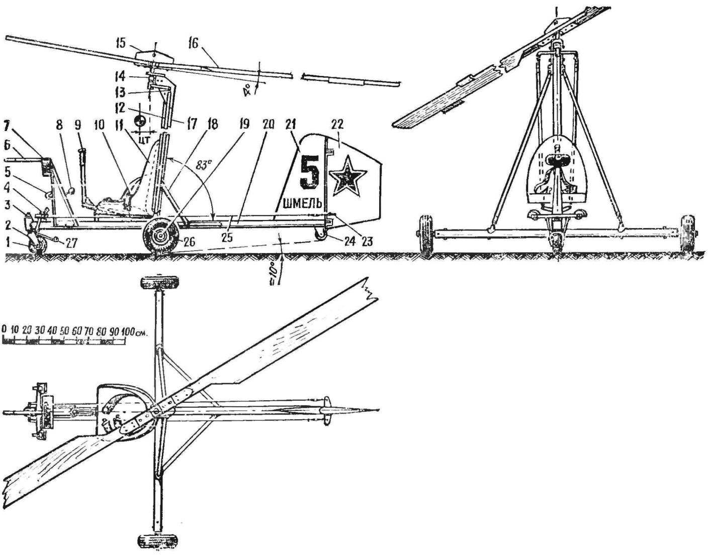
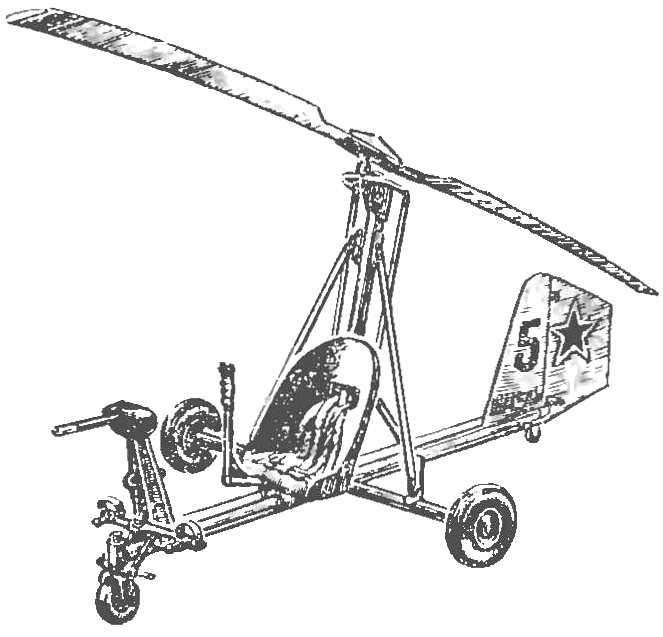
Microaction “Bumblebee”:
1 is a front-wheel driven (kinematically associated with the pedal upravlennya rudder), 2 — wheel plug, 3 — pin plug, 4 — pedal upravlennya rudder, 5 — hook towing lock, 6 — receiver airspeed indicator, 7 — instrument cluster, 8 — lever uncoupling the towing lock, 9 — control knob bearing screw, 10 — seatbelts, 11 — seat pilot, 12 — thrust upravlennya rotor, 13 — hinge top plug control 14 — shaft rotor, 15 — farm of the rotor, 16 — blade propeller, 17 — pylon 18 — rear strut pylons, 19 — axle side wheel chassis 20 longitudinal tube of the frame-base, 21 — Kiel, 22 — the rudder, a 23 — horn of the rudder 24 to the tail wheel (hockey puck), 25 — rope of the rudder 26 — side wheel chassis, 27 — brake plate front wheel.
Rotor blade — pine. Spar — from Delta-wood, metal spout made of brass, it is strengthened through rivets. The foam is only used to fill the tailed part of the blade after half of its magnitude — to the terminal part. The blade is fully glued with epoxy glue, is processed according to the contour and profile, and then it cut out window filled with foam. The surface is cleaned, glued plywood with a thickness of 1 mm, is cleaned again, glued cloth and painted. Tests showed that the blades of this design have a resource much greater than recommended by Yu RISCOM (“M-K”, 1970, № 10). Latest crack after a few flights. The alignment made by us blades is in the range of 24% of MAR.
The center of gravity of the assembled gyro needs to be in the range of 40 to 80 mm ahead of the axis of rotation of the rotor (depending on the weight of the pilot). If when checking the alignment, which must be very carefully carried out before flight is detected it will shift in either direction from the specified values, you should secure the appropriate weight in the tail or the nose of the gyroplane.
Instrumentation consists of a speed indicator, variometer, turn and slip, altimeter and clock.
Wheels (both main and nose) is best suited from the little micro-car-map — they are lighter and much more flexible aircraft “quilted”. To introduce the design of the chassis damping elements undesirable, as the gyroplane becomes “Jumpy” and landing you can catch the rotor for ground.
In order to avoid deformation and damage of the rotor during storage of the gyroplane between flights (if it stays under the open sky) will be back up and tie them to the blades of a stout cord. Bush thus should be inhibited.
A. MACKIN, head of special design Bureau “Rise”, D. Vishnyakovo, Moscow region
Recommend to read
 “DIPLOMAT” FOR INFLATABLE
Free time, whether it is a holiday or weekend, we as a family try to spend Hiking: Hiking and Biking, road and water. Visited the Baltic States, Karelia, the Crimea, the Caucasus, in the... NOT THE RING FINGER
Sometimes it is difficult to remove on finger tight ring, but much harder — pressed on the shaft bushing or bearing, Not accidentally creating a variety of devices. One of such devices...