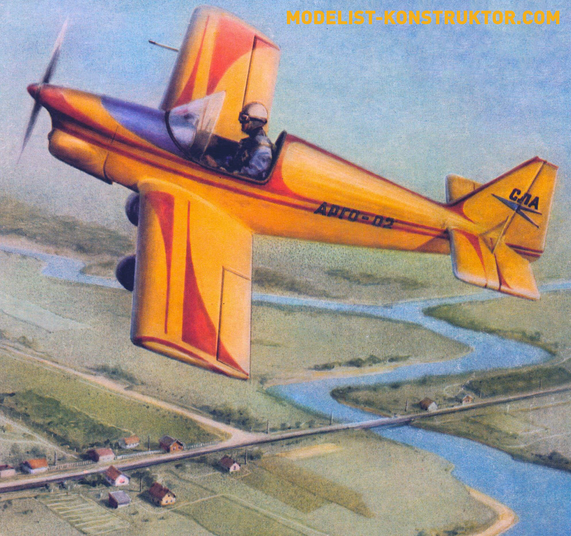
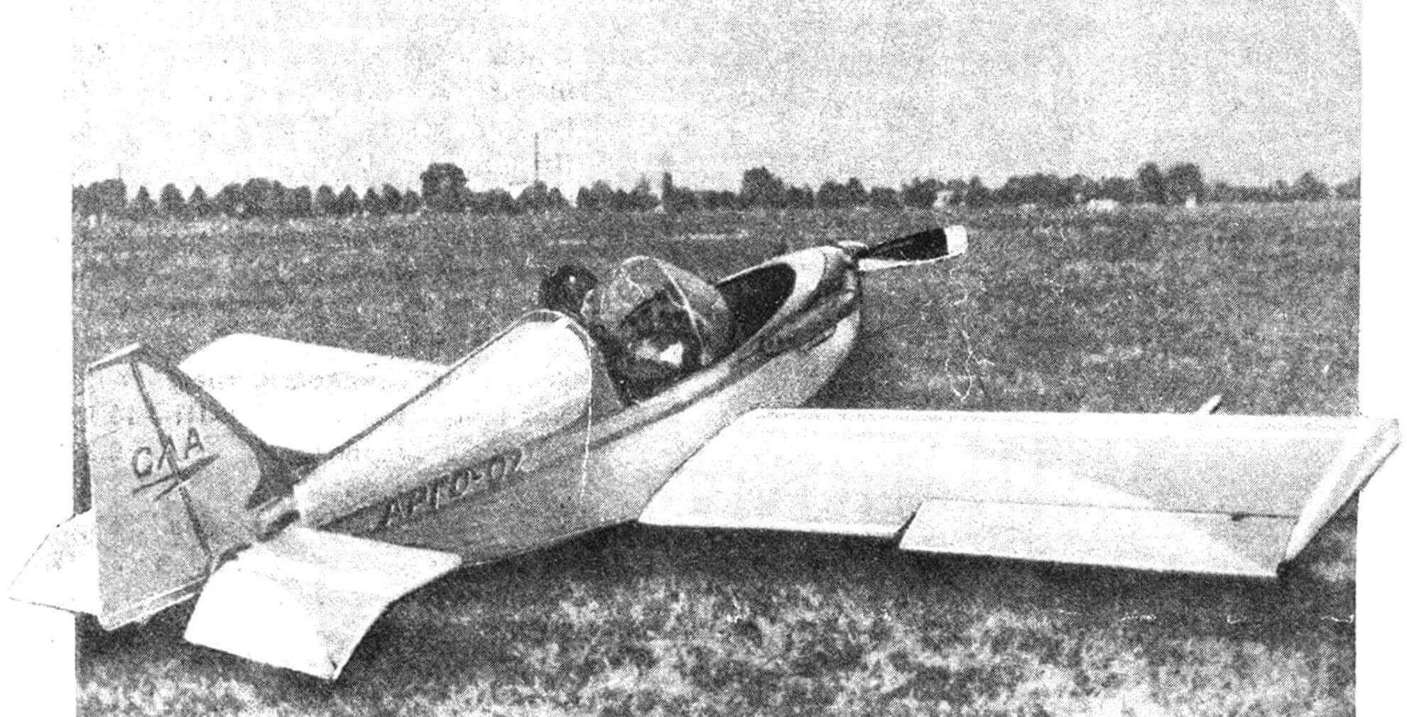
Is it possible in our time, which is called a period of total shortage, to build an airplane yourself? Tver amateur aviators Evgeny Ignatiev, Yuri Gulakov and Alexander Abramov answered this question in the affirmative, creating a winged single-seat aircraft, later called Argo-02.
The plane turned out to be successful: it successfully flew at the All-Union SLA competitions in 1987 and 1989, and was the first prize-winner of the regional review-competition of amateur aircraft in Yaroslavl. It aroused increased interest among amateur aircraft designers – both the Argo developers and the editors of the Modeler-Constructor magazine received many letters asking them to tell more about this aircraft on the pages of M-K.
The secret of the increased popularity of the Argo is not in the design or technological delights of the designers, but rather in the traditional design and technological techniques used to create the aircraft. The developers managed to achieve a successful combination of techniques for constructing wooden cars of the 20s and 30s, worked out over many decades, and modern aerodynamic ideas about aircraft of this class. This, perhaps, is one of the main advantages of the aircraft: its production does not require modern plastics and composites, rolled high-strength metals and synthetic fabrics – you only need pine timber, a little plywood, canvas and enamel.
The Argo is a single-spar wing aircraft: its frame consists of a box spar and a set of truss ribs made of pine lath. The wing skin is linen, and only the wing tip, which receives torque, is covered with plywood. The fuselage is a pine truss with the same fabric skin in the rear section and plywood in the nose. The plumage is a lightweight openwork braced truss covered with canvas. The chassis is of a completely modern design – it is a fairly simple steel spring. The engine was initially a four-stroke from a heavy Ural motorcycle, then equipped with a gearbox and a lighter two-stroke RMZ-640. Even today, such a motor can still be “obtained” in a store.
However, the simplest design from the simplest materials is just one of the components of the machine’s success. In order for all these pine slats and pieces of plywood to fly, they need to be “fitted” into very specific aerodynamic shapes. In this matter, the authors of “Argo” – we must give them their due – showed enviable design wisdom. For their aircraft, they chose the aerodynamic design of a classic cantilever monoplane with a low wing and a pulling propeller. Nowadays, against the backdrop of a wide variety of canards, tandems and other wonders of modern aerodynamics, an Argo-type aircraft even looks conservative. But this is where design wisdom lies: if you want to build an original plane, make a “duck”, but if you want to build a flying plane, choose the classic design: it will never let you down.
However, that’s not all. In order for an airplane to fly well, it is necessary to correctly determine the ratio of its mass, engine power and wing area. It is difficult to say whether the authors were helped by accurate calculations, design intuition, or good knowledge of the statistical data of such aircraft, but the parameters of the Argo can be considered optimal for a device with an engine power of 28 hp. With. The parameters of the Argo can be taken as a model if someone wants to build a similar aircraft. It is these ratios of parameters that provide the best flight performance characteristics: speed, rate of climb, take-off run, mileage, etc.
At the same time, stability and controllability are determined by the ratio of the area of the wing, tail and rudders, as well as their relative position. And in this area, as it turned out (which the designers of the Argo understood very well!), no one has yet invented anything better than the standard classical design, and on the Argo the parameters are taken straight from the textbook: the area of the horizontal tail is 20% of the wing area , and vertical – 10%, the tail arm is 2.5 times the aerodynamic chord of the wing, and so on, without any deviations from the classical design rules, from which there is obviously no point in departing.
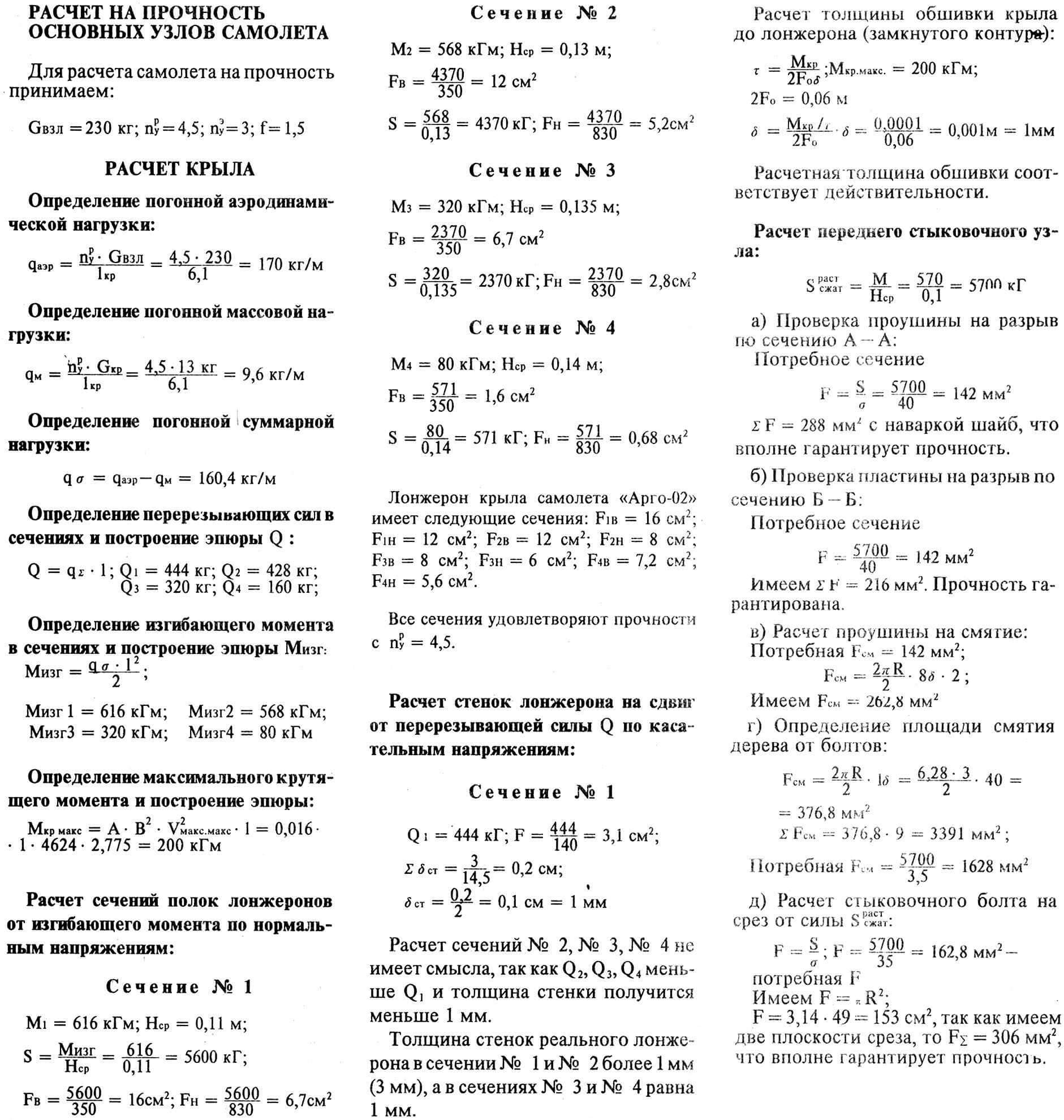
The aerodynamic data of the aircraft even made it possible to perform aerobatic maneuvers on it. But aerobatics means not only successful aerodynamics, but also high structural strength. According to the calculations of the authors and the technical commission, the Argo could withstand an operational overload of no more than 3, which is quite sufficient for circling flights and short routes without complex evolutions in the air. In short, aerobatics for this device was categorically contraindicated.
But, apparently, the successful and calm flights “pancake across the horizon” soon bored the authors and pilots of the Argo. The fact that the strength of the aircraft is insufficient for aerobatics was forgotten. The turns gave way to deep turns, then rolls, flips… On August 18, 1990, while performing a demonstration flight at a holiday dedicated to Air Fleet Day, Yuri Gulakov introduced the Argo into another coup. This time, the speed turned out to be slightly higher than usual, and the maximum operational overload, obviously, far exceeded the calculated “three”. As a result, the Argo’s wing collapsed in the air, and the pilot died in front of the assembled spectators.
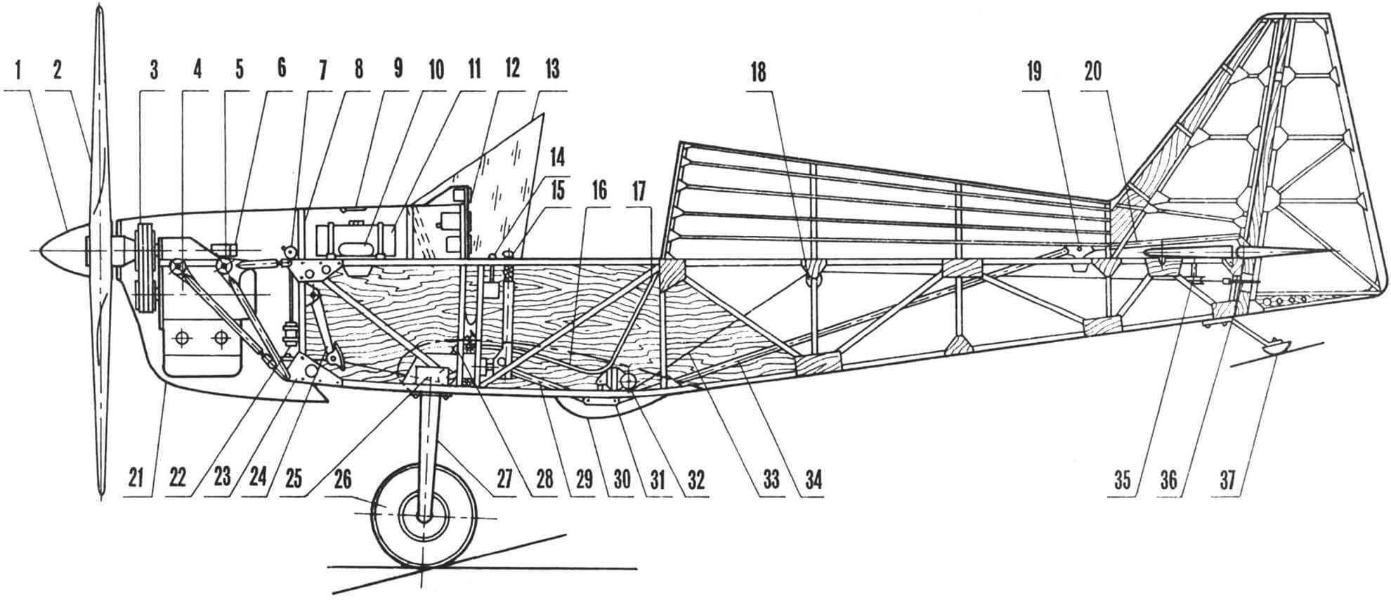
1 — propeller spinner (glued from fiberglass), 2 — propeller (glued from pine), 3 — V-belt gearbox, 4 — engine type RMZ-640. 5 – sub-engine frame (welded from 30KhGSA pipes), 6 – tachometer sensor, 7 – check valve, 8 – firewall, 9 – gas tank filler flap, 10 – compensator, 11 – fuel tank (welded from sheet aluminum), 12 – instruments (navigation and flight control and engine control), 13 — visor (plexiglass), 14 — engine carburetor throttle control handle (throttle lever), 15 — roll and pitch control handle, 16 — pilot’s seat (fiberglass glued with epoxy binder ), 17 — seat back, 18 — block of control cable wiring rollers, 19 — intermediate elevator rocker, 20 — elevator rod, 21 — engine hood (glued from fiberglass with epoxy binder), 22 — fuel filter, 23 — fastening unit motor mounts, 24 — suspended yaw control pedals, 25 — spring chassis mounting unit, 26 — chassis wheel 300X125 mm, 27 — chassis spring (steel 65G), 28 — filler syringe, 29 — elevator control rod, 30 — fairing (sticking made of fiberglass on an epoxy binder), 31 — intermediate elevator control rocker, 32 — block of rollers for rudder control cables, 33 — rudder control cable, 34 — elevator control rod, 35 — block of rollers for rudder control cables, 36 — rudder drive lever, 37 — tail support (crutch).
Here one could “read the moral” about the need to comply with flight rules, about flight discipline and other important things. However, as experience shows, such instructions do not bring any benefit until the pilot himself understands that there is no place for violations of discipline in aviation. It’s a shame that sometimes it comes too late.
As a rule, such tragic cases, even with all the obviousness of the reasons causing them, force us to look for errors in the design and calculations of the aircraft. However, in relation to the design of the Argo-02 aircraft, this is not required: the machine withstood exactly what it was designed for.
That is why the technical and flight methodological commissions for amateur-built aircraft of the USSR Ministry of Aviation Industry recommend the Argo-02 aircraft as a prototype for independent construction in amateur conditions.
DESIGN, TECHNOLOGY, CALCULATIONS
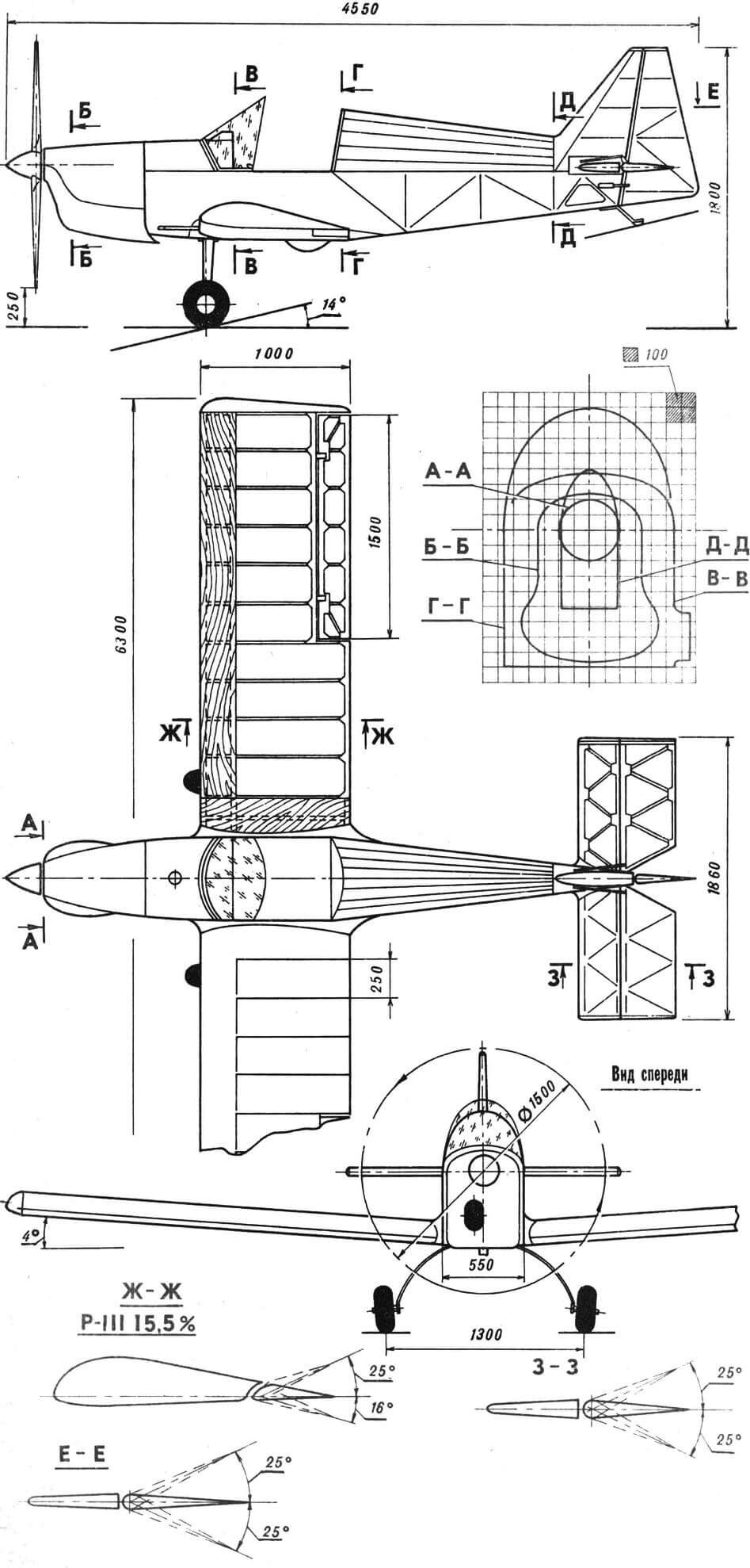
“Argo-02” is an ultra-light training cantilever monoplane of a classic wooden structure with a lower wing and a cantilever tail. The aircraft has a spring-type landing gear with a tail support.
The aircraft’s power plant is a two-stroke two-cylinder air-cooled engine of the RMZ-640 type, which drives a two-blade wooden monoblock propeller through a V-belt gearbox.
The control system of the Argo-02 aircraft is of a normal type. The pilot’s cockpit is equipped with flight team instruments and engine control instruments.
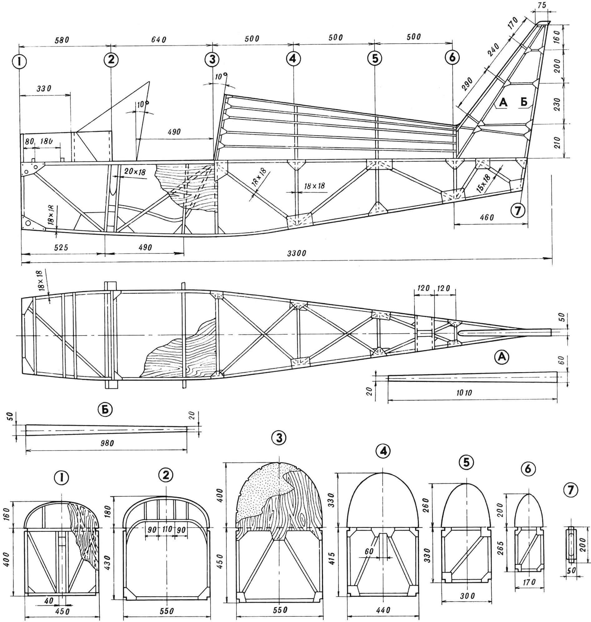
The fuselage of the aircraft is made of wood, with a braced-truss structure. The fuselage spars are wooden slats with a cross section of 18X18 mm.
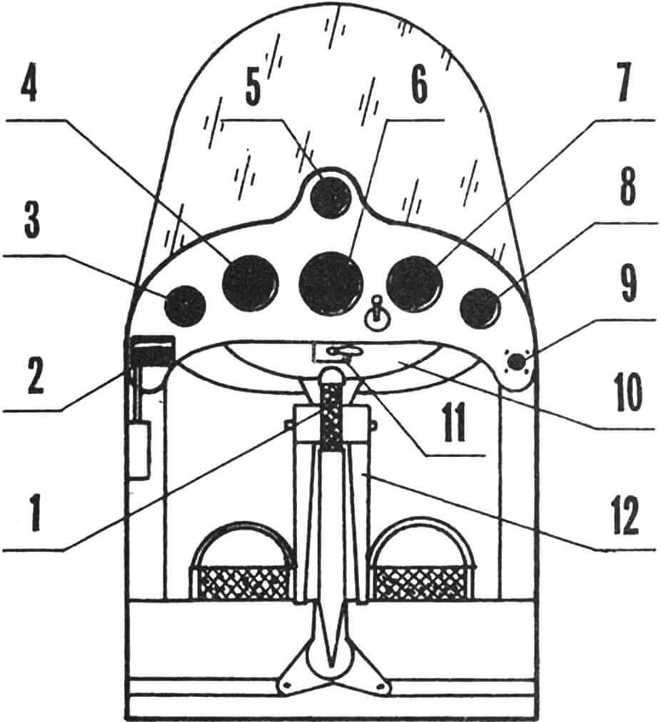
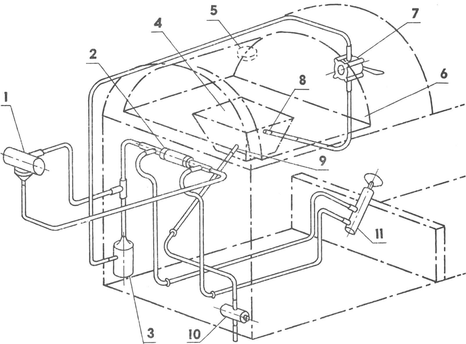
1 — control handle, 2 — engine carburetor throttle control handle (EC), 3 — TGC, 4 — VR-10, 5 — EUP, 6 — US-250, 7 — VD-10, 8 — TE-45, 9 — shock absorber, 10 — fuel tank, 11 — fire hydrant, 12 — direction control pedals.
Behind the cabin of the aircraft, on top of the fuselage, a lightweight garrot is installed, the basis of which is foam diaphragms and stringers. There is also a garrot in the front part of the fuselage, in front of the cabin – it is made of wooden diaphragms and casing made of sheet duralumin 0.5 mm thick.
The pilot’s cabin is covered with plywood 2.5 mm thick. The rear part of the fuselage in the area where the stabilizer is attached is also covered with the same plywood. All other surfaces of the fuselage are lined.
The center section spars pass through the pilot’s cabin, which are used to attach the pilot’s seat to them, as well as the manual control station of the aircraft. The chair is molded from fiberglass and covered with faux leather.
The inside of the cabin is covered with foam plastic, and on top of it with artificial leather. On the left side of the cabin there is an throttle control lever – the engine carburetor throttle control handle.
The instrument panel of the aircraft is knocked out of sheet duralumin and covered with so-called hammer enamel. In the cabin it is attached to frame No. 3 on shock absorbers. The following devices are mounted on the dashboard: TGC, US-250, VR-10, VD-10, EUP, TE and the ignition switch. There is a fuel tap under the board, and a filler syringe on the front side member.
In the front part of the fuselage, under the garrot, a fuel tank with a capacity of 15 liters is fixed.
The landing gear attachment points are installed in the lower part of the fuselage in front of the front spar. On the front frame, which is also a fire barrier, a link-type pedal mounting unit and a foot control roller fixation unit are attached. On the other side of the firewall, a check valve, a fuel filter and a drain valve are mounted.
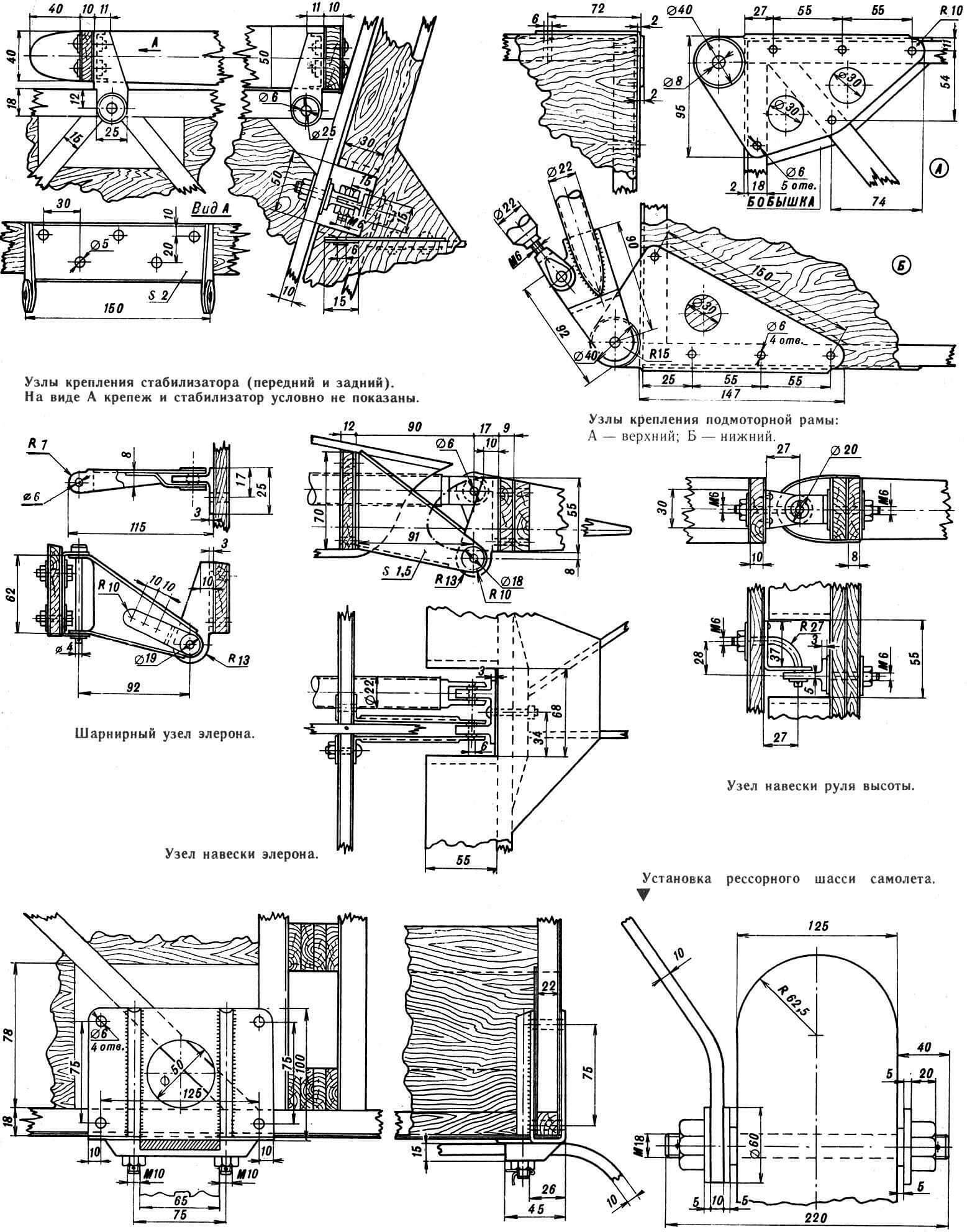
The motor mount attachment points are installed at the points where the side members join the front frame. The motor mount itself is welded from chromansil (steel 30KhGSA) pipes Ø22X1 mm. Rubber shock absorbers are provided at the points where the engine is attached to the motor mount. The engine is enclosed by upper and lower cowlings molded from fiberglass. The propeller blank is glued together from five pine plates with epoxy glue and, after final processing, covered with fiberglass using an epoxy binder.
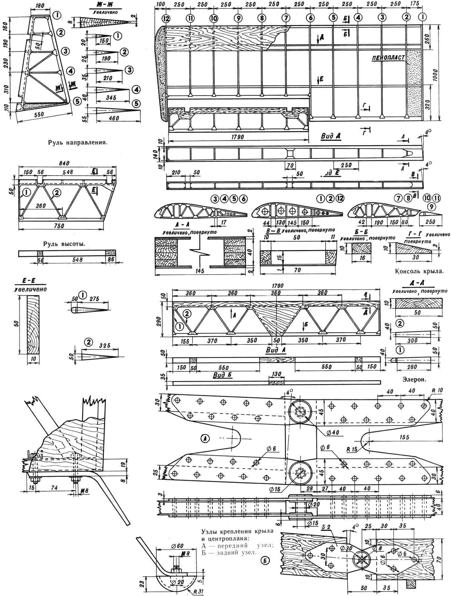
Wing. The basis of each wing is a longitudinal and transverse set. The longitudinal one consists of a main spar, an auxiliary (wall), a frontal stringer and a flow fin. The main spar is two-flange; it consists of upper and lower shelves made of pine slats of variable cross-section: at the root of the wing, the upper shelf is 30X40 mm, at the end section – 10X40 mm; the bottom shelf is 20X40 mm and 10X40 mm, respectively. Diaphragms are installed between the flanges in the area of the ribs. The spar is covered on both sides with plywood 1 mm thick; in the root part – plywood 3 mm thick. Wooden bosses are installed in the root part of the wing and the aileron rocker attachment area.
The joints between the wing consoles and the center section are mounted in the root part of the wing on the front (main) spar. The docking units are made of steel grade 30KhGSA. A mooring unit is mounted at the end of the spar.
1—roll and pitch control handle of the aircraft, 2—engine carburetor throttle control handle (EC), 3—rudder, 4—elevator, 5—aileron, 6—heading control pedals.
The front stringer of the wing frame is made of a wooden lath with a cross-section of 10X16 mm, the tail stringer is made of a wooden lath with a cross-section of 10X30 mm. From the toe to the front spar, the wing is covered with 1 mm thick plywood. A ladder is formed in the root part of the wing from plywood 4 mm thick.
The transverse set of the wing consists of normal and reinforced ribs. Reinforced ones (ribs No. 1, 2 and 3) have a beam structure and consist of shelves with a section of 5X10 mm, racks and a plywood wall 1 mm thick with lightening holes.
Normal ribs have a truss structure. They are assembled from shelves and braces with a cross section of 5X8 mm, assembled using scarves and booklets.
The wingtips are foam. After processing, they are covered with fiberglass with an epoxy binder.
The aileron is slot type. Its frame consists of a spar with a cross-section of 10X80 mm, ribs cut from plates 5 mm thick, an attack rib and a flow rib. The toe of the aileron is covered with plywood 1 mm thick, and together with the spar, the sewing forms a rigid closed profile resembling a semicircular pipe. The aileron linkage units are mounted on the spar. The response brackets of the aileron linkage are mounted on the rear wing spar. All surfaces of both the aileron and the wing itself are covered with canvas.
Plumage. The horizontal tail of the Argo-02 aircraft consists of a stabilizer and elevators. The stabilizer has a two-spar design with ribs placed at an angle – this provides the stabilizer with high torsional rigidity. The toe of the stabilizer up to the front spar is covered with 1 mm thick plywood. The stabilizer can be used in both cantilever and braced versions. To implement the second option, strut attachment points are installed on the rear spar. The attachment points for the stabilizer to the fuselage are mounted on the front and rear spars. The elevator linkage units are located on the rear stabilizer spar; their design is similar to the design of the components of the A-1 airframe. The ends of the stabilizer are foam plastic, covered with fiberglass. The central part of the stabilizer is covered with plywood.
The elevator consists of two parts, which to some extent duplicate each other. Each part consists of a spar, diagonally placed ribs, rib toes and flow ribs. The nose of the steering wheel is covered with plywood 1 mm thick. The elevator control horn is fixed in the root part of the steering wheel.
The vertical tail consists of a keel and a rudder. The keel is structurally integral with the fuselage according to a two-spar design. The front part of the keel (up to the front spar) is covered with plywood. The rear spar is a development of the rear fuselage frame.
The design of the rudder differs little from the elevator and ailerons. It also consists of a spar, straight and braced ribs and a fin. The front part of the steering wheel up to the spar is covered with plywood. The steering wheel mounting units are fork bolts. The steering control lever is fixed in the lower part of the spar. The strut mounting unit is also mounted on the steering spar. All plumage is covered with canvas.
Chassis. The landing gear of the aircraft consists of the main landing gear and the tail gear. The main chassis is two-wheeled, spring type. The spring is curved from steel 65G; the wheels are attached to the ends of the springs. Wheel size – 300X125 mm. Fastening the spring to the fuselage using a steel plate and two bolts on each side – the spring is clamped with their help and thereby fixed relative to the fuselage.
The tail support is a strip bent from 65G steel, to which a support cup is screwed from below. This strip is attached to the fuselage with two bolts.
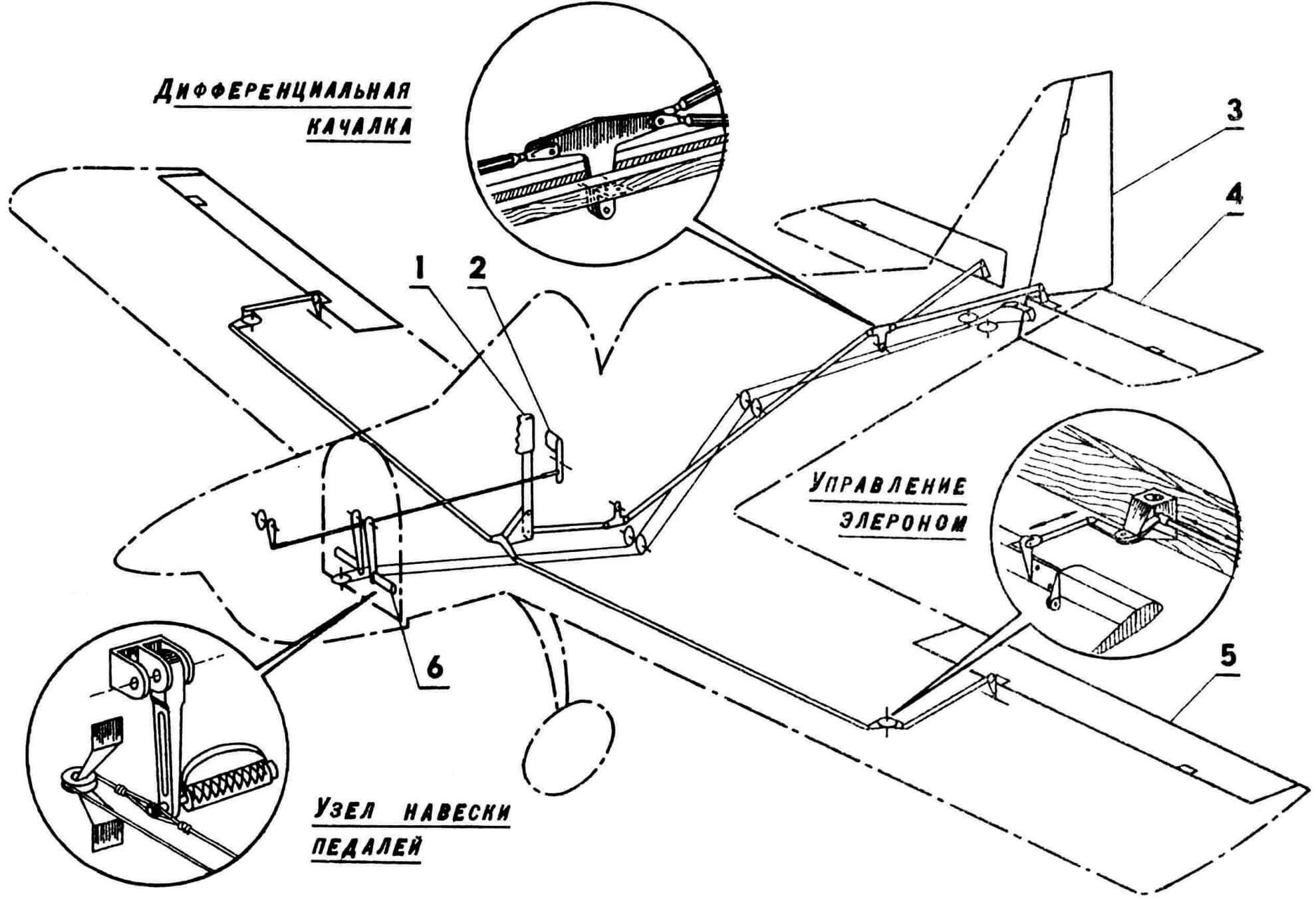
The elevator control is hard. It is carried out using a control handle (a handle from the Yak-50 is used), duralumin rods and intermediate rockers.
Aileron control is also tight. The steering wheel drive is cable driven. It is controlled using suspended lever pedals, steel cables with a diameter of 3 mm and textolite rollers with a diameter of 70 mm. To prevent foreign objects from getting into the control units, the floor and control route are covered with a decorative screen.
Power point. The basis of the power plant is the RMZ-640 type engine. It is installed on the engine mount in an inverted position – with the cylinders down. On top of the engine is the upper pulley of the V-belt gearbox with a belt tensioning mechanism.
Fiberglass cowlings are secured with screws to self-locking anchor nuts on the fuselage and connecting ring.
The propeller spinner is mounted on a duralumin ring and secured with screws. The spinner is made by gluing from fiberglass with an epoxy binder.
Fuel system. The fuel system includes a fuel tank with a capacity of 14 liters, a fuel pump, a fuel filter, a check valve, a fire tap, a drain valve, a tee and a pipeline system.
1 – carburetor, 2 – check valve, 3 – fuel filter, 4 – consumable capacity, 5 – traffic jam with drainage, 6 – fuel tank, 7 – fire tap, 8 – fitting fitting, 9 – drain fitting, 10 – drain tap , 11 – a flood syringe.
The fuel tank is boiled from an aluminum sheet with a thickness of 1.8 mm. In the lower part of the tank is a consumable container into which the consumable and drain fittings are welded. In the upper part of the tank is a bay neck with drainage. Inside the tank, communicating partitions are located to prevent fuel foaming. The tank is fixed on two beams using solid tapes with felt gaskets.
Air pressure receivers system. The PVD system consists of a PVD tube (from the Yak-18 aircraft) installed on the left plane of the wing, the tubes of dynamic and static pressure, connecting rubber hoses, the distributor and devices.
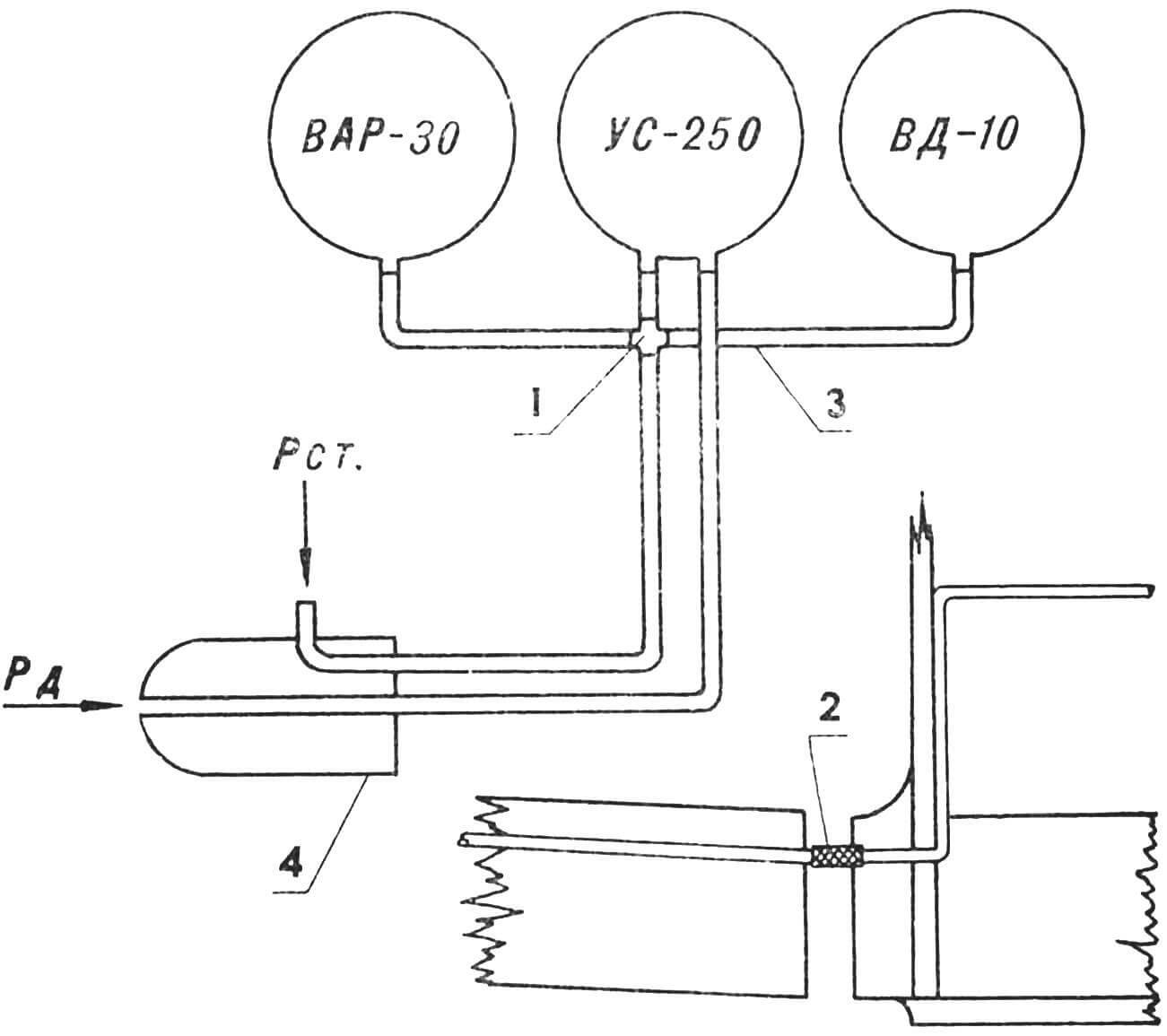
1 – static pressure distributor, 2 – Dyutic hose, 3 – aluminum pipeline, 4 – air pressure receiver (PVD).
Air propeller. The ARGO-02 air screw is glued from pine plates on epoxy resin, and then processed according to the templates, covered with fiberglass and painted. On the plane, several screws of this design with different diameters and steps were used. One of the most acceptable in its aerodynamic qualities has the following characteristics: diameter – 1450 mm, step – 850 mm, chord – 100 mm, static thrust – 85 kgf.
Flight and technical data of the aircraft
Length, m – 4.55
Height, m - 1.8
Wing scale, m – 6.3
Wing area, m 2 – 6.3
Wing narrowing – 0
End wing chord, m – 1.0
Sah, m – 1.0
The angle of installation of the wing, hail. – 4
Angle V, hail – 4
The angle of arrow, hail. — 0
Wing profile-p-III-15.5%
Eleron Square, m2 – 0.375
Eleron’s scope, m – 1.5
Eleron deviation angles, city:
Up – 25
down – 16
Grand -th, m – 1.86
Square GO, m 2 – 1.2
The angle of installation GO, hail. — 0
RV area, m2 – 0.642
Square in, m2 – 0.66
Height V, M – 1.0
Square pH, m2 – 0.38
The angle of deviation pH, city. ± 25
RV deviation angle, city. ± 25
The width of the fuselage in the cabin, m – 0.55
The height of the fuselage in the cabin, m – 0.85
Wheel chassis base, m – 2.9
The track of the chassis, m – 1.3
Power plant-RMZ-640 engine with a silencer, cooling air
Power, l. With. — 28
Max, rotation frequency, 1/min – 5500
Reducer-cuneiform, four-armed, A-710 belts
Rush number – 0.5
Fuel-gasoline A-76
Oil-MS-20
Screw diameter, m – 1.5
Screw step, m – 0.95
Static traction, kgf – 95
Mass of an empty apparatus, kg – 145
Maximum take -off weight, kg – 235
Fuel reserve, L – 15
Range of flight centers, % sah 24 … 27
Stinging speed, km/h – 72
Max, horizontal flight speed, km/h – 160
Max, piloting speed, km/h – 190
Cruising speed, km/h – 120
Deping speed, km/h – 80
Landing speed, km/h – 70
The speed of the Earth, m/s – 2
Run, m – 100
Mileage, m – 80
Range of operational overload +3 … –1.5
Dimensions during transportation, m – 5×2.3×1.8
V. Kondratyev, Alexander Abramov, Tver
Recommend to read
 THE STRINGS OF THE SKI…
"Could you tell us about how to make a sports bow?". George Grudev (Bulgaria), Nikolay Kuznetsov (Kursk) etc. to Make a sports bow by all the rules that only an experienced master.... RACING “WING”
Looking through the model magazines for the last couple of years, you've probably noticed a sharp change in the appearance cord racing model aircraft. They have disappeared, it would...
