The frame consists of two main parts, connected in the middle by a hinge with a vertical axis of rotation. The front part is welded rigid node on which you installed the axle, engine, fuel tank, foot controls and the driver’s seat. Left carrying the arc of the frame also serves as a silencer.
Hinge with a vertical axis of rotation consists of two forks, United powerful fingers. The fingers of bolts attached to lugs of the rear fork, and the front turns in a thrust and needle bearings.
So the wheels are not rubbing against each other when you “break” the frame around a vertical axis, the hinge has limiters that are installed respectively at the front and rear forks: slightly curved and tapered for stiffness-hook and two studs on the ends of the channel brackets. The rear part of the frame to the attached axle, brake and detachable body is movable, the hinge of her – with a horizontal axis of rotation. But it works a little differently: to the rear fork riveted fixed cover with internal thread, into which is screwed a bronze nut. She serves as a bearing for a movable cover of the rear part of the frame.
Scheme of transmission:
1,3 – axle front axle; 2, 10 – differentials; 4 – output shaft; 5 – chain; 6 – front propeller shaft; 7 – connector; 8 rear drive shaft; 9, 11 – rear axle shaft
Suspension (from the top view the engine and seat conventionally not shown):
1 — fuel tank; 2 — engine; 3 — fixing bracket of the steering column; 4 – exhaust pipe; 5 – the Central mount of the engine; 6 – housing differentials; 7 – steering column; 8 – steering rod; 9, 10 – limiters of the angle of “break” the frame; 11 – the terminator-bolt body; 12 – a steering worm gear; 13 – cover front propeller shaft; 14 – the connecting link; 15 — casing rear drive shaft, 16 – loop fastener of the body; 17 – gear shift lever; 18 – the gas pedal; 19 – the bottom bracket of the engine; 20 – clutch pedal; 21 – day; 22 – the suction inlet of the muffler; 23, 29 – flanges of semiaxes; 24 – step; 25 – supporting the arc of the frame (muffler); 26 – exhaust pipe; 27 – bellcrank steering; 28 – supporting the arc frame; 30 – lock brakes; 31 – brake drum; 32 – rear drive shaft; 33 – bracket steering gear; 34 – front propeller shaft; 35 – housing of the chain transmission; 36 – the rear bracket of the engine; 37 – brake handle
In the sleeve, this casing is held by a stud, screwed into the reinforcing lining. She’s the limiting angle of “break” the frame relative to the longitudinal axis of the vehicle. The value of the angle depends on the length of the groove is sawn in a stationary casing and the sleeve.
The engine of the VP-150M installed across the movement to take less space, and fan for cooling it had the most favorable conditions for work.
Mounting brackets are located as follows: the Central and most powerful – on the housing of the differential, under the cylinder of the engine, the lower right beam of the bridge, under the Carter and the rear on the casing of the chain transmission.
To the crankcase of the engine mounted metal fuel tank capacity of 5.5 liters; the fuel in the carburetor flows by gravity.
Controls are placed on beams of the front axle: left pedal clutch, right side gas. For the convenience of the driver near the pedals installed foot pegs.
Gears are shifted by hand using a lever with a ball on the end welded to the toothed sector
The engine starts with the kick starter with the handle instead of folding pedals.
The exhaust gases from the cylinder for corrugated pipe fall into the left support tube of the frame as the muffler and out the exhaust pipe under the seat.
Transmission the vehicle is symmetric about the vertical axis of the “break” the frame. Torque from the engine circuit is transmitted to the propeller shafts, and from them through bevel gears and differentials – axle shafts bridges.
Drive shafts machined from bar. In the middle of them – under the seal of the neck and at the ends of the slots. Driveshafts with universal joints (including connecting link) is taken from the motorcycle “Ural”. They rotate in bronze bearings which are lubricated from time to time through a thin tube ttings bred out.
The articulation of the drive sprocket with the differential and front driveshaft:
1 – pinion gear bevel gear; 2 – a casing of the differential gear; 3, 7 – tapered roller bearings; 4 – spacer; 5 – adjusting gasket; 6, 12 stud M6; 8 – cuff; 9 — the case of the bearing unit; 10 – bolt M4; 11, 18 – halves of the casing; 13 – inner flange; 14 – a rivet d 3 mm; 15 – driven sprocket; 16,20 – M4 screws; 17 – a lining; 19 – hinge bracket of steering gear; 21 – nut M 14×1,5; 22 – outer flange; 23 – front driveshaft
Install the brake drum:
1 – rear propeller shaft; 2 – outer flange; 3, 8, 12 stud M6; 4 – drum; 5 – inner flange; 6 – nut M 14×1,5; 7 – a brake disk; 9 – the case of the bearing unit; 10 cuff; 11, 15 – tapered roller bearings; 13 – adjusting spacer; 14 – spacer; 16 – the differential case; 17 – pinion bevel gear
The external splines of the propeller shafts are in outer flanges connecting them with the shafts leading bevel gears gears. The rear shaft is equipped with a brake of the scooter “Vyatka”: brake disc with pins attached to the housing of the bearing unit, and the drum -flanges. The control cable from the disc placed on the steering column.
The differentials of the axles on the Rover – traditional design: with two gears-satellites (from the car “Moskvich-412”), the Side gears made, and bevel gear taken from the motorcycle “Ural”.
The cracker, in contrast to the “moskovichevskoe”, has a spherical surface facing the differential housing, a cylindrical, for simplicity.
Bridges are attached to the frame with bolts, bushings and shims. Only on the rear axle bolts still hold the hinges to the body, and the front – mounting brackets of the gas pedal and clutch.
Steering consists of a removable steering wheel, vertical column, steering worm gear, two rocking chairs and adjustable pull. The gear ratio of the actuator 1:4, which allows to “break” the frame not only in movement but also in the Parking lot. The force from his thrust is transmitted to the rocking chair, a fork attached to the rear of the frame, and causes it to deviate in one direction or another.
The wheel is also structurally simple and identical. Bearing element each of them is aluminum, the hub, the ends of which are screwed to the discs of the same material.
Design of joints “break” the frame:
1 – cap; 2 – screw M3 (4 PCs); 3 – housing cuffs; 4 cuff; 5 – front propeller shaft; 6 front cover; 7 — an overlay; 8 — front seat; 9 — height adjustment; 10 – front fork; 11 – a tube-limiter of the angle of “break” frame; 12 – the case of the needle roller bearing; 13 sleeve; 14 – stud-stop angle of “break” the frame; 15 — mounting brackets pins-limiters; 16 – finger-axle “break” the frame; 17 – thrust ball bearing; 18 – the needle bearing; 19 – bellcrank steering; 20 – rear fork; 21 – lubricator; 22 – limiter-bolt body; 23 is a reinforcing lining; 24 — a movable casing; 25, 27,33 – bronze sleeve-bearings; 26 – the fixed casing; 28 – the screw M5 (2 PCs), 29 – a M6 bolt of fastening of a finger of the axis (6 PCs); 30 – bolt M6 (8 PCs.); 31 – connector; 32 – bolt M6 (4 PCs); 34 – Kardan
Rear axle:
1 – wheel flange; 2 – oil seal; 3 – cover; 4 – housing; 5 – shaft bearing; 6 – cuff; 7 – Circlip; 8 – beam axle; 9 – shaft; 10 – cover; 11 – bevel gear; 12 – pin M8 coupling; 13 – a cracker; 14 – finger of satellites; 15 – Satellit; 16 stud M6; 17 – differential bearing; 18 – housing shaft bearing; 19 – pump; 20 – halves of the differential housing; 21 – supporting the arc of the frame; 22 – cap; 23 – shim; 24 – liners; 25 – M8 pinch bolt; 26 – a loop body mounting
Wheel:
1 – M8 bolt attachment to the axle flange; 2 – hook (wire d3 mm); 3 canvas belt; 4 – clip (d4 mm wire); 5 – hole for the valve; 6 – a nave; 7 discs; 8 – cover
Body:
1 – front bracket; 2 – side brackets; 3 – rivet d3 mm; 4 – M4 screws
Drives wire hooks and brackets attached eight canvas straps hold the bus – two cameras size 720×310 mm, nested one inside the other and secure the canvas band with pockets-cleats.
The outer end of the hub is closed, protecting its cavity from contamination, and the interior is fitted with four bolts for attaching the wheel to the axle flange.
The body is assembled from welded steel frame and a glass fibre laminate panels. The necessary rigidity of the floor give a three channel with brackets for installation on the frame of the vehicle.
Body weight only 6.5 kg, however, its dimensions are such that allow an adult to sit without experiencing much inconvenience.
Technical care of the vehicle almost minimal. It is sufficient to monitor the level of fuel in the tank, the gear oil in axles and the air pressure in the tires. Yes, occasionally lubricating bronze bushings-bearings through the grease fittings.
A. GROMOV, A. TIMCHENKO
Recommend to read SANDING FIBERGLASS In the manufacture of personal watercraft, hidrocaribe and other small-tonnage vessels to protect the surface from moisture and make the case the mechanical strength is widely used... TANK, WHOSE “SWINGING” TOWER Oscillating turret French light tank AMX-13 was only one of the features of this machine. Another feature is a violation of the creators of the familiar classic layout, when the power...
Scroll back to top

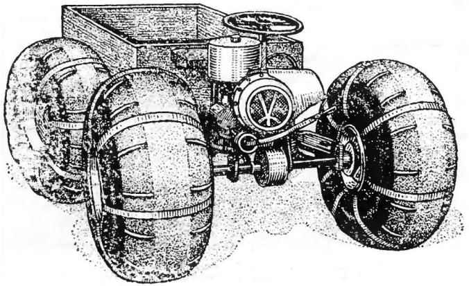 The vehicle is made according to the scheme proven by the tractor “Kirovets”. He has the same “breaking” the frame and drive on both bridges. What gives? First, the good permeability. Frame, continuously curving, as if tracking the terrain. All four wheels are constantly in contact with the surface. This eliminates the overload of individual wheels and slip them on the uneven ground. Second, increased maneuverability. The hinged frame is sensitive to even the slight deflection of the steering wheel and allows you to turn almost on the spot. Thirdly, constructive simplicity. In this scheme, you can use exactly the same front and rear axles. Simple turns and the engine mount.