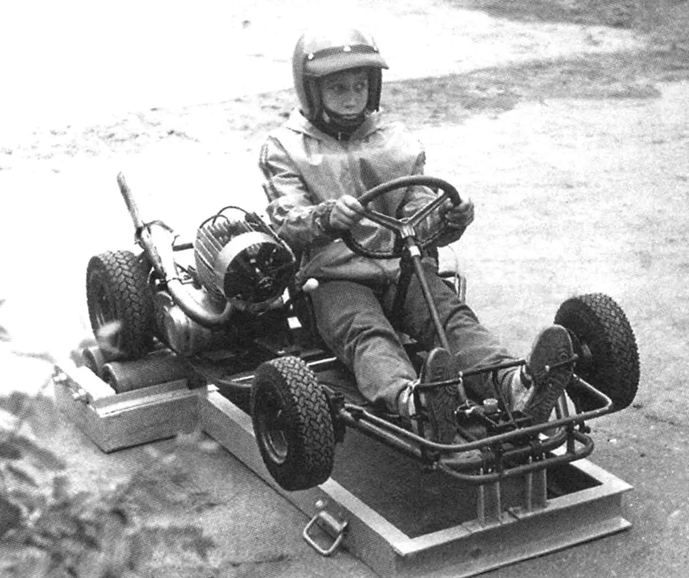
Many youth technical clubs and stations (КЮТ and СЮТ) have karting sections. The small machine not only helps kids learn the general concept of how a car works and master the basics of driving, but also paves the way for many of them into big-time motorsports and reveals their potential in technical creativity.
The karting training program provides for the initial stage of acquiring skills in manipulating the clutch, throttle, brake pedals, and gear shift lever. However, the latter action is prohibited by the operating instructions when the engine is not running, as it can lead to damage to the gear shifting mechanism. With the engine running, it is simply unsafe: the kart is set in motion, and the trainee, essentially sitting behind the wheel for the first time, does not yet know how to control it.
Even if a СЮТ has a real automotive simulator, after training on it, kids still do not achieve the desired effect in acquiring kart driving skills. The kart is a very specific machine, as are its controls. Even the driver’s seating position is different.
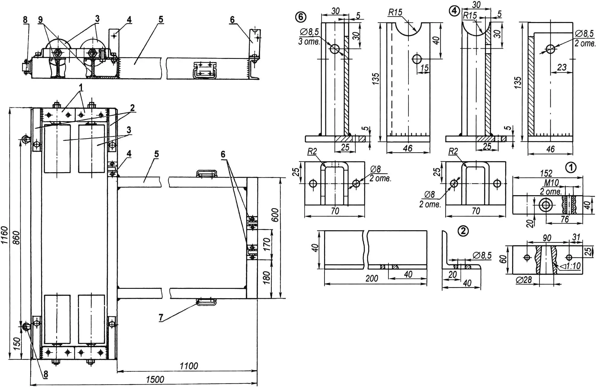
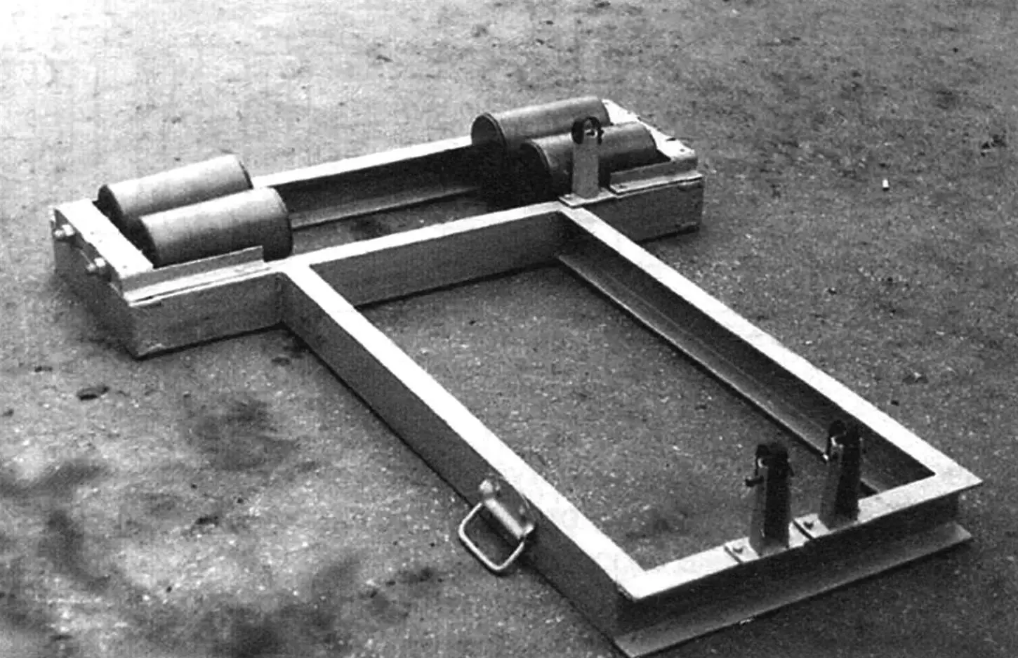
1 — roller supports (Ст3, 4 pcs.); 2 — roller support holders (angle 40×40, 4 pcs.); 3 — rollers (4 pcs.); 4 — side bracket (Ст3, sheet s5); 5 — frame (channel № 10); 6 — front brackets (Ст3, sheet s5); 7 — handle (2 pcs.); 8 — wheel (2 pcs.); 9 — ribs (Ст3, sheet s5, 4 pcs.)
In some sections, initial exercises for manipulating kart pedals are conducted by raising the rear wheels — placing the rear part of the frame on stands. But this is also unsafe — the kart can “slide off” the stands due to vibration. For the engine and gear shifting mechanism, this method is also harmful — the motor runs without load at high speeds “in neutral,” and smoothly shifting gears in this case is simply impossible, so machine breakdowns are quite likely again.
We found a way out of this situation by designing and manufacturing a training stand that meets the requirements of the training program and safety regulations.
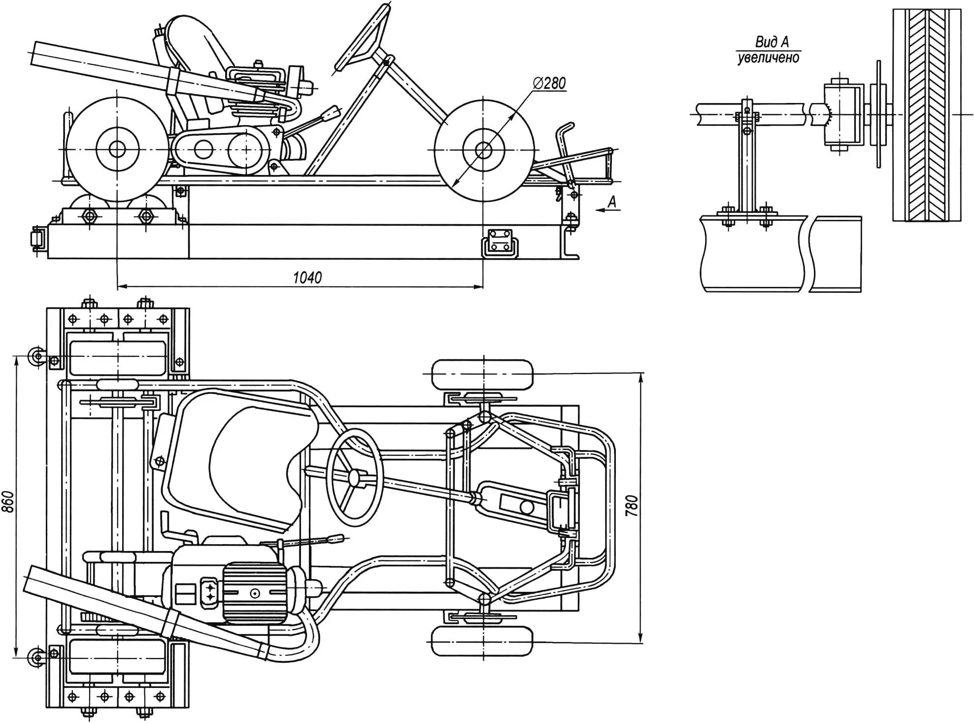
The foundation of the stand is a frame welded from channel № 10 (but it can also be made from channel № 8). It consists of two rectangles joined in the shape of the letter T.
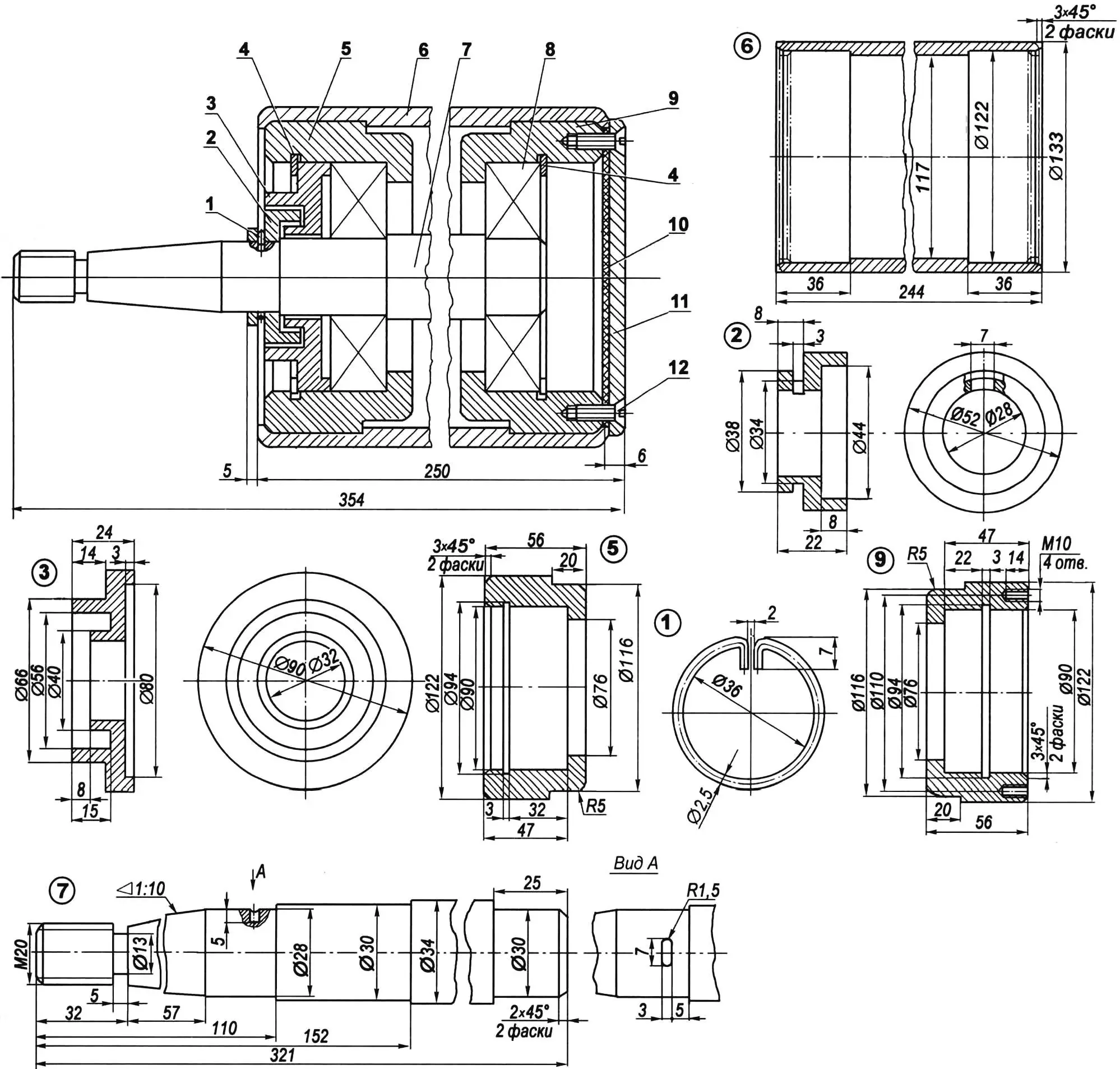
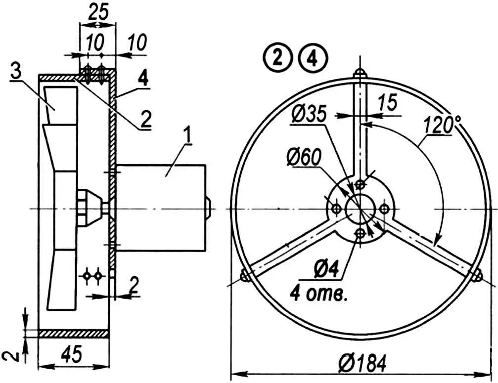
1 — retaining ring (wire Ø2.5); 2 — small labyrinth bushing; 3 — large labyrinth bushing; 4 — thrust rings (Ст3, sheet s2); 5 — bearing housing (steel 45, round 122); 6 — roller housing (steel 45); 7 — axle (steel 45, round Ø34); 8 — bearing 80406 (2 pcs.); 9 — thrust bearing housing (steel 45, round 122); 10 — rubber gasket (s3); 11 — cover (Ст3, sheet s6); 12 — screw M6х12 (4 pcs.)
At the top, on the sides of the rear part of the frame, 4 roller supports (2 right and 2 left) are installed. Each of them is a block with conical holes for the roller axle, with a welded bracket made of 40×40 mm angle.
To increase rigidity, rib plates are welded between the channel flanges under the roller axles.
At the top of the stand frame, three brackets are fixed: two front ones — under the kart frame crossmember and one side — under the side member. The first two hold the machine in place, and the last one prevents it from shifting from vibration in the lateral direction. The kart frame tubes are pulled to the brackets with belts secured on bolts.
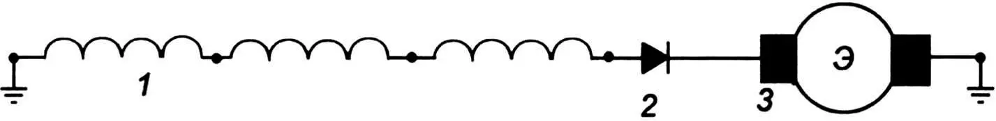
1 — generator winding; 2 — rectifier (diode Д231 А); 3 — electric motor М367
The most complex unit of the stand to manufacture is the roller, and there are four of them — two for each driving rear wheel.
Two housings with bearings 80406 are inserted and rolled into the cylindrical hollow roller housing from opposite sides. The bearings are mounted on an axle, which is secured in the support by its conical part.
On one side, the roller is closed with a cover with a rubber gasket, on the other — with labyrinth sealing bushings.
Consistent grease is packed into the bearings and into the bushing gaps. The assembled roller should rotate freely. The force required to set it in rotation should not exceed 3.2 kgf/cm.
1 — electric motor; 2 — housing shell (sheet s2); 3 — five-blade impeller (from “Zhiguli” car); 4 — electric motor holder
Before mounting on the stand, the kart was also modified. First, a fan with an М367 DC electric motor with a voltage of 6 V and a power of 5 W — from the С3Д motorized wheelchair windshield wiper — was installed on the motor. However, the generator on the kart is AC. Therefore, the electric motor is powered from it through a single-diode rectifier Д231А. The fan impeller is five-blade — from a “Zhiguli” car. It is enclosed by a ring guard.
The assembled fan is attached using a bracket to the kart frame at the location where the engine is installed.
Fuel flows to the carburetor by gravity from a 1.5-liter metal tank mounted at the rear on the seat back.
A muffler from a serial “Minsk” motorcycle is installed on the stand kart, as these machines have the same engine displacement — 125 cm3.
Before each training session, the stand on the site must be positioned so that the wind is directed at the trainee’s face and carries away exhaust gas from the muffler.
For moving the stand, two wheels are mounted at the rear on the frame end, and two handles on the sides of the front part of the frame. The stand is lifted to a vertical position by them and transported to the desired location.
On the rotating rollers of the stand, the kart moves as if on the road: all gears engage clearly, engine speed increases smoothly, and the brakes do not “lock” even when the pedal is pressed sharply.
The training stand was manufactured in the “Karting” section of the КЮТ of the Syzran Turbine Plant and, together with the kart modifications, was registered as a rationalization proposal. Section members A. Baev and A. Kuzmin took an active part in creating the stand.
Years of operation of the training stand have demonstrated its safety and increased the effectiveness of teaching kids the initial kart driving skills.
«Modelist-Konstruktor» № 5’2006, V. STANOTIN, teacher
Recommend to read
 DIEHARD CHESS…
I love to play chess, and I imagine it is a shame, if the Board in the most interesting moment goes — well, for example, when you carry it from one table from another. I have had several...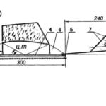 FLYING UNDER THE ROOF
For many school model aircraft clubs create room flying models is the only available form of modeling. Judge for yourself: the season of the competition model, as a rule, coincides with...
