
Few car owners do not try to improve their consumer qualities.
The most extensive field of activity for auto-rationalizers is the power plant. From time to time, publications appear about gaskets, attachments, or additives that increase engine life, optimize fuel consumption, reduce exhaust toxicity…
Our Ukrainian reader proposes an aerodynamic attachment for the carburetor. He claims that his innovation noticeably improves the quality of the carburetor’s operation, reduces fuel consumption, as well as the load on the connecting rod-piston group of the engine.
When I first heard the hissing sound with which a working carburetor sucks in air, I wondered: are its diffusers really that effective?
From aerodynamics, it is known that a streamlined body does not cause disturbance (turbulence) of the incoming air flow. A non-streamlined one, with its ledges, creates zones of rarefaction, in which vortices immediately form. It is no coincidence that the air intakes of aircraft are carefully “smoothed out,” otherwise the vortices “sitting” on the ledges sharply reduce the actual passage cross-section of the intake device.
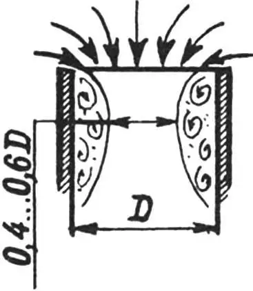
Isn’t the same thing happening in the carburetor’s diffuser? At idle speed of an automobile engine (on average 1000 rpm), the speed of the incoming air flow at the carburetor inlet is 5—6 m/s. This is sufficient for a ring vortex to form at the upper edge, which behaves partly like a throttle valve, blocking the carburetor throat by almost half (Fig. 1). Hence the lack of air, enrichment of the fuel mixture, and, as a result, increased fuel consumption. I emphasize: already at idle!
The higher the number of revolutions, the stronger the rarefaction in the intake tract, the greater the flow velocity, the more powerful the vortex, and, consequently, the thinner the stream of air penetrating into the carburetor. The excess rarefaction behind it has to be overcome by pressing the accelerator pedal, which means additional fuel consumption and engine wear due to increased load on the connecting rod-piston group.
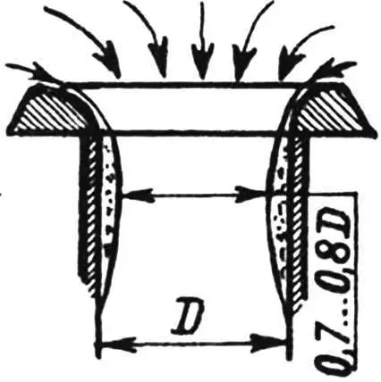
The initial flow velocity in the air intakes of subsonic aircraft and hovercraft is approximately the same as in an automobile carburetor. However, there the intake devices are profiled so that vortices have nowhere to “sit.”
Using reference literature on aerodynamics, I found the theoretical profile of an attachment (Fig. 3) that would help optimize the airflow around the intake device of a DAAZ carburetor on my VAZ-21011 car.
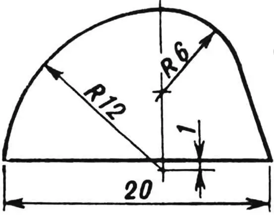
I made two parts of the attachment — rings — on a lathe from a steel pipe (can be made from duralumin or even polymer). To do this, I turned the pipe from three sides, bringing its outer and inner diameters to 80 and 40 mm respectively, and controlled the end profile with a template made of sheet metal. I cut off the first ring with a thickness of 11 mm.
Then I turned and cut off the second ring, since the DAAZ carburetor is two-chamber.
I made the third part of the attachment, exactly repeating the contours of the standard clamping plate of the air filter housing (the standard one has under-stampings and is not suitable for mounting rings on it), from sheet steel 1.5 mm thick and immediately drilled four holes with a diameter of 6.2 mm along the edges for studs to attach to the carburetor.
Next, having aligned the diffuser openings of the new clamping plate and the rings, I filed the latter, giving them outlines corresponding to Figure 3. Without disassembling the parts, I drilled six holes with a diameter of 3.3 mm in them. In the blind holes of the rings, I made M4 threads, and the holes in the plate I drilled out to a diameter of 4.1 mm and countersunk for the heads of countersunk screws.
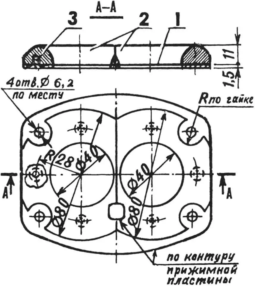
1 — plate; 2 — rings; 3 — screw
M4 (6 pcs.)
The last operation — connecting the rings and the clamping plate with “Moment” glue and M4 screws.
I tested the first attachment back in 1987 on my VAZ-21011, although I only patented it in 1997 (Russian Federation Patent No. 2084679 with priority from 1993). I felt a significant difference in the car’s behavior immediately, when accelerating from a standstill. Fuel consumption on the highway was significantly lower than usual.
To date, about twenty such attachments on carburetors have been installed. I don’t even know some of their owners, but most are my acquaintances, so there’s always someone to ask.
What are their results? On different cars (from VAZ-21011 to VAZ-21099), the attachment gives different effects, as much depends on the engine condition. However, in all cases, gas analyzers record reduced CO content in the exhaust at idle and increased speeds.
Y. BELOSHENKO, Antratsyt, Ukraine
Recommend to read
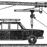 Car lift in the garage
When I bought a used passenger car and started repairing it, my first helper in the garage became... a hoist I built under the ceiling. Without it I would hardly have managed, for example,...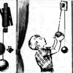 SWITCH FOR GROWTH
If necessary, almost any switch can be very simply converted so that they could be used by both adults and children. This will require a strong nylon thread and two balls of different...
