For remote monitoring of the serviceability of stop-light lamps in a car, transistor electronic («Modelist-Konstruktor» No. 6’2000) or relay-transistor devices are usually used. The latter is part of the standard electrical equipment of some cars as relay 4402.3747 and represents a design of magnetically controlled HERmetically sealed CONtacts — reed switches («Modelist-Konstruktor» No. 7’91, 4’98, 5’99) and powerful transistor amplifiers.
I propose two variants of a more economical stop-light controller (KCC), the homemade current relay of which contains a powerful reed switch. Since the operating principle of both devices is the same, it is more expedient to consider their operation using the example of the schematic electrical diagram of the simpler one.
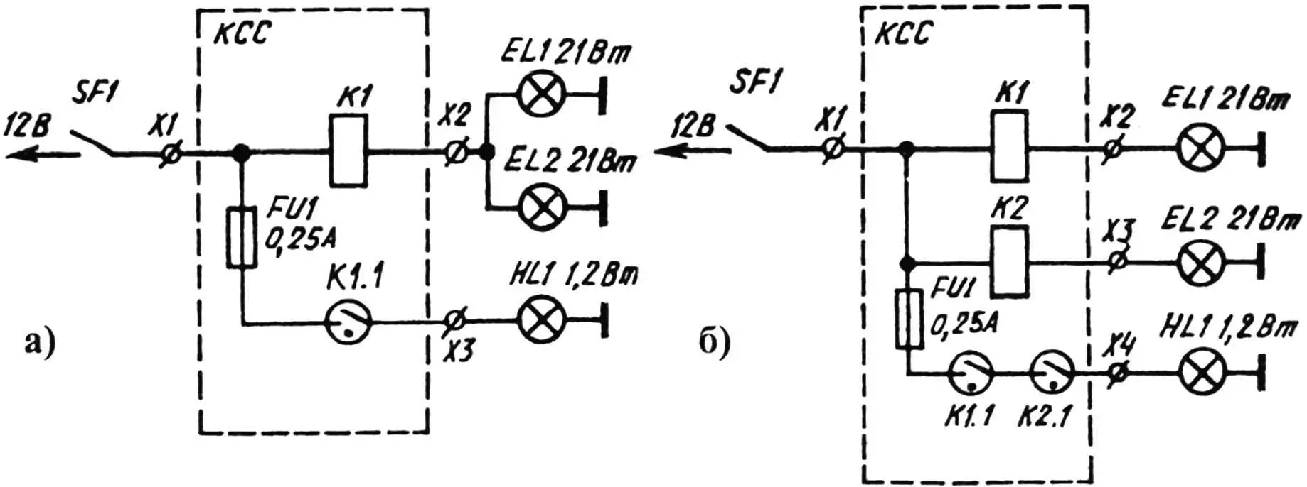
When braking, the limit switch SF1 on the brake pedal connects the stop-light lamps EL1, EL2 and the current winding of relay K1, which surrounds the reed switch K1.1, to the power source. The latter, closing under the influence of an instantly arising magnetic field, turns on the control indicator lamp HL1 on the instrument panel. Its glow during braking indicates the proper operation of EL1 and EL2. When there is a break in the circuit (burnout) of one or both stop-light lamps, the current through the relay winding is insufficient to close the reed switch or is absent altogether, as a result of which HL1 does not light up when pressing the brake pedal.
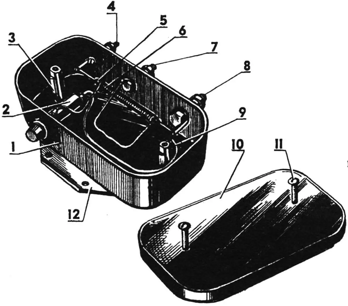
The device is designed so that a current of 1 — 1.5 A flows through the reed switch at the moment of its closing, which is 10—15 times higher than the operating mode of the control lamp. The duration of the starting current pulse is no longer than 0.1 s. Based on these data, the type of reed switch is selected. As practice has shown, KEM-1 or MKA-52142 with permissible switching currents of 2 and 3 A respectively are suitable here. The reed switch K1.1 is protected by fuse FU1 from damage in case of accidental short circuit in the control (indicator) lamp HL1 circuit. The stop-light controller is assembled in a plastic box measuring 112x62x40 mm.
The current relay is made as follows. The KEM-1 reed switch has a total length of 79 mm, glass bulb length of 50 mm, and bulb diameter of 5.4 mm. The corresponding dimensions for MKA-52142 are 79, 52, and 5.5 mm. On the glass bulb of the reed switch, a single-row winding K1 is laid (secured with BF-2 glue), containing 35 turns of PEV2-1. Its DC resistance is 0.015 Ω, and the voltage drop across it does not exceed 0.05 V.

1 — plastic housing; 2 — fuse; 3 — stand-bushing M4 (2 pcs.); 4 — terminal for connecting indicator lamp 1.2 W (M4 bolt with two nuts); 5 — reed switch KEM-1 (MKA-52142); 6 — relay winding (35 turns of PEV2-1); 7 — terminal for connecting two signal lamps 21 W (M5 bolt with two nuts); 8 — terminal for connecting to limit switch SF1 on brake pedal (M6 bolt with two nuts); 9 — mounting wire PMV-1.2; 10 — plastic cover; 11 — M4 screw (4 pcs.); 12 — metal base (with six mounting holes Ø4.2)
Adjustment of KCC comes down to selecting the number of turns of the current relay winding K1, which should operate with necessarily two serviceable stop-light lamps connected in parallel to contact X2 of KCC. If operation is observed with one EL1 (or EL2), then several turns need to be unwound.
The controller is installed in the car trunk. A reserve lamp in the standard instrument cluster is used as the control HL1.
The device made according to the complicated schematic electrical diagram does not need adjustment thanks to the fact that the stop-light lamps are connected to the power source through the current winding of an “individual” relay. However, for this, it is necessary to lay an additional wire in the car’s electrical wiring to one of the stop-light lamps.
In conclusion, one more clarification. The device made according to any of the given circuits is suitable for a vehicle with arbitrary polarity of the onboard network with a voltage of 6 or 24 V and stop-light lamp power of 10 or 40 W respectively.
A. TRIFONOV
Recommend to read
 CAR-TRUCK
Car-truck individual in the household - an indispensable means of transport even for those who have a mini-tractor or motoblock with a trailer. Its main advantages - environmentally... ’95 FORD EXPLORER
Every year in the U.S., sold to 450 thousand SUVs this model, which gives reason to talk about him as "popular" American jeep. The growing popularity of this car in Russia. The first...
