LET THE WIND

LET THE WINDThe wind has always been a symbol of impermanence, and attempts to transform its energy into electrical energy has led often to results that are not very encouraging. Indeed, everything you expect from the source of electrical energy stability: clicked the switch and turned on the light. And the wind, alas, changeable. However, to make it a reliable source of electricity possible, to use already well developed scheme with intermediate energy storage battery.

During the day the wind turbine rotates the generator, which by means of the electronic device charges the rechargeable battery. Depending on the wind force and low power consumption sets the optimal charge current and stabiliziruemost voltage regardless of the frequency of rotation of the generator. In today’s collection, readers are offered two wind power plants (WPP): classic — horizontal and rotary with a vertical axis of rotation.
 
Disk
 
WES is going based on car units 12-volt alternator and battery, capable to provide a country house lighting (three or four 20-candle lamps), as well as energy to power portable TVs and other 12-volt appliances.
 
To bring the rotation of the generator (example: Zhigulevsk with current returns 42 But the rotation frequency of 5000 rpm), you will need a wind wheel with a diameter of 1500… 1800 mm. the Drive generator is carried out through chain multiplier (accelerating gear) with a ratio of 3…4.
Blade propeller is best done of birch or pine bar. First cut the workpiece propeller, representing its planned projection with a 5 mm seam allowance. On it are laid out the contours of the blades with the planes of the control sections. Be careful when making the profile of the propeller from how well it is made, depends on the efficiency of wind turbines, or, equivalently, the energy output of the generator.
 
To get a blade of the desired profile, you first need to procure the screw drawing the rear and front edges of the blade determining the angle of attack of each of the sections. Next, using a semicircular chisel and rasp to cut through “beacons” — lots of profile in the areas of control sections and paint them with colored pencil. Between the “beacons” selected wood; the correct profile of the blade is controlled with a ruler imposed on neighbouring arch Painted with colored pencil section when processing should remain intact.
 
Wind Farm
 
The Installed Capacity Of The Disk:
 
1—generator of type G-221; 2—two-bladed wind wheel; 3—chain transmission multiplier; 4—cantilever axis of rotation of the propeller; 5 — cone of the hub of the propeller; 6—hub of the propeller (brake drum motorcycle); 7—brake shield with brake pads; 8—bracket cantilever axis propeller; 9—frame; 10—powertranslator node; 11—bearing; 12—guide keels; 13—automatic braking device

 
Ready propeller vyshkurivaetsya and fixed on the hub, which is used as the brake drum motorcycle wheels: this allows to have not only a compact bearing unit, but a simple auto braking device.
 
After installation on the hub of the propeller must be balanced. For this purpose, the axis of rotation of the screw is fixed in a vise and using a rasp and sandpaper is facilitated by the heavier blade. A properly balanced propeller should stop after a rotation in any position.
 
The finished screw is covered with several layers of varnish parquet with intermediate Vykurovanie and finally fixed on the hub.
 
The frame of the wind turbine welded steel angles section of 40x40x3 mm. of the same parts assembled and the bracket, in which is fixed the axis of rotation of the propeller. The guide keels (“tail”) of the windmill are cut from plywood with a thickness of about 6 mm. a Joint of the rotary device is a steel ball between the reference fifth, is pressed into the stationary rack, and a connecting area of the movable stand. On the free end of the last installed a nylon bushing.
 
As already mentioned, the rotation of the propeller to the generator is transmitted through chain multiplier with a ratio of 3…4. For this purpose, the Bicycle sprocket between the hub and propeller — anchor, a shaft generator is driven. Alternator mounting using standard brackets ensures optimal chain tension.
The wind turbine must be equipped with an automatic brake, preventing the increase of frequency of rotation of the propeller is above the permissible level with a sharp wind. The most simple variant — with the use of a motorcycle braking device. On the axis of the Cam instead of the brake lever is worn with a sleeve welded to it the tubular rod. The last two fixed plywood blades. Regular spring tightens the brake pads replaced by a different, less strict Parameters of the spring are selected depending on the size of the blades of the braking device and the length of the rod. Braking propeller should begin when the wind speed 12… 15 m/s, but with very strong wind, the wind wheel itself will stop.
 
The electronic unit of the rectifier-stabilizer BPV-14-10 (this is used on type motorcycles “IZH” and some cars) rectifies three-phase alternating current produced by the generator, and stabilizes voltage at currents up to 10 A. in addition, the unit provides battery charging and switching consumers with the power from the battery to the generator and Vice versa, while changing the rotation frequency of the last or power load. The rectifier-stabilizer is mounted on the frame near the generator.
 
Swivel-manifold knot
 
The rotary collector node:
 
1—support of wind power; 2—base plate (steel sheet thickness 5 mm); 3 — front commutator brushes (steel channel cross-section 30×50 mm); 4—stationary front rotary device (steel pipe d40 mm); 5 — movable front rotary device (steel pipe d50 mm); 6—washer-restrictor (Teflon or nylon); 7—bearing heel; 8—ball joint; 9—reinforcing the gusset plate; 10—docking site (steel sheet thickness 5 mm); 11—insulating bushing collector ring; 12—bolt with nut, washer and grommet-isolator; 13—collector ring; 14—compression spring; 15—brush commutator device; 16—insulating gasket

 
Schematic diagram of the wind farm
 
A circuit diagram of a wind farm:
 
1 —car generator type G-221; 2—electronic rectifier-type regulator BPV-14-10; 3 — battery (12 V, 50…60 And h); And — fuse; 5—consumers.
CI, C2, and W—phase stator windings of the generator; M1 and M2 excitation winding of the generator; -the XI —minus winding; -x2—”minus” of the battery; XS is positive pin of the test light; X4, X5 and X7—phase stator windings of the generator; +X8—plus battery

 
You can, of course, to equip the wind power installation of another electronic unit that converts DC to AC voltage of 220 V, but the efficiency of such a device is not too large, and it will be another source of losses in the chain of energy conversion.
 
To transfer power from the rectifier-stabilizer to the battery, installed under the mast of the wind turbine, is performed using a simple reservoir, consisting of a pair of rings on the tilt of the mast, and a pair of contact brushes. Of course, the “positive” ring manifold and the corresponding contact brush must be securely isolated from the “masses”. To exclude the ingress of moisture collector closes the plastic “umbrella”.
 
The mainstay of the wind farm except for a welded mast can serve as a wooden or concrete pole, similar to those used for power lines. If selected as a support pillar, it is necessary to fix it, at least three extensions of steel cable or wire.
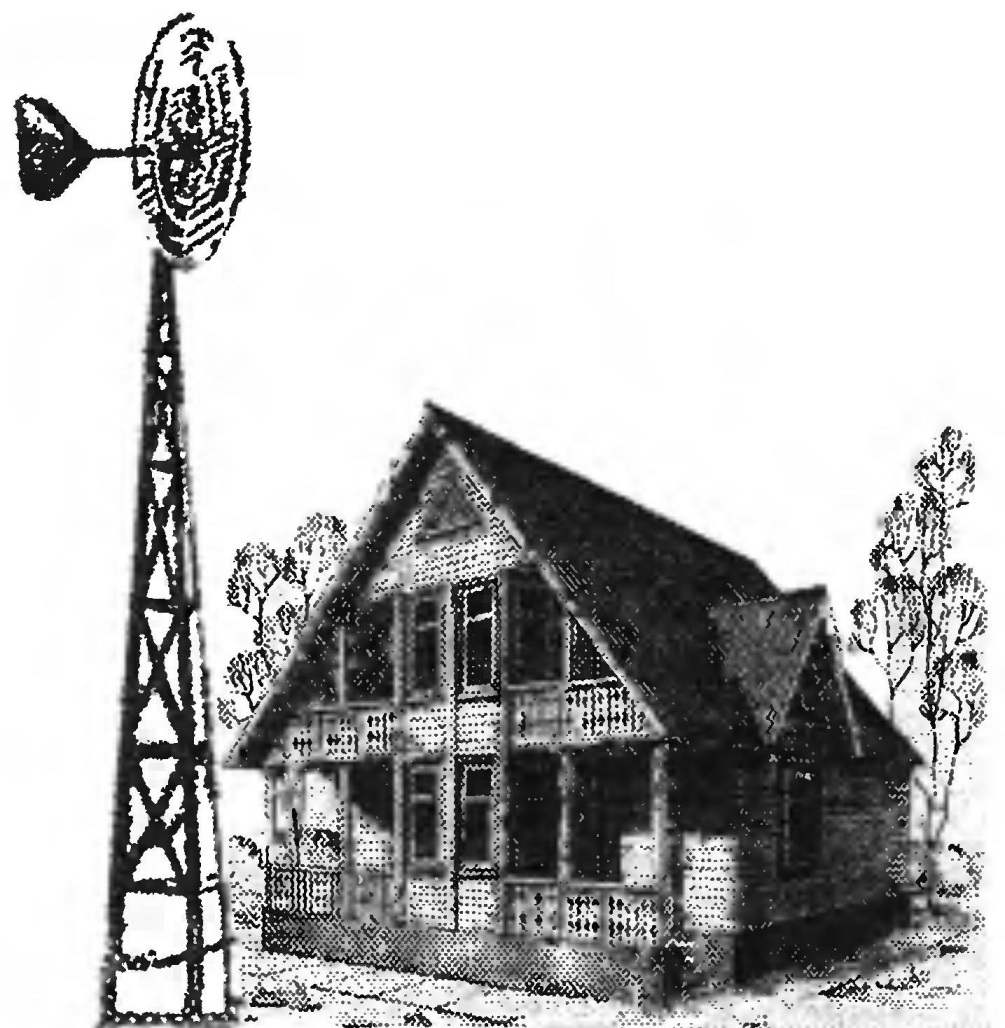
Note that the installation height of the propeller depends on the presence of obstacles (trees, buildings, and other structures) located in the immediate vicinity. Ideally, the blade of the propeller must be above nearby obstructions not less than two meters. You must consider that the impact of obstacles on the air flow extends to a distance equal to fifteen times its height.
 
Wind power plant with horizontal axis of rotation, despite the relatively high efficiency, has its drawbacks. In particular, the transfer of large current through the collector causes significant losses of energy and can lead to trouble as due to contact failure during their oxidation, and reduce the elasticity of the plates, brush gear. And again, the wind wheel of this type has the qualities of a gyro — gyroscope tending to maintain the space orientation of the axis of rotation. Therefore, the changes in wind direction occurs a significant load on the bearings, reducing their service life.
 
“Rotor”
 
In many cases, more viable rotary wind farm, which wind wheel has a vertical axis of rotation and can operate at any wind direction.
 
There are several types of rotary wind turbines. One of the simplest and most effective is WindRotor representing cut on a diametrical plane of a hollow cylinder with an offset relative to each other parts. This rotor although Tehachapi propeller, but has more torque and able to work under negligible wind speeds. The main thing is its ability to rotate in any wind direction and as a consequence — the absence of the rotary device and the collector.
 
The advantages of VES with vingretto-ROM is the simplicity of its design.
 
A rotary turbine mounted on a pole or mast. How this is done, readers already know from the description of the WEC of the type “Disk”. The base is welded from steel angles section 4x40x40 mm. In the upper part is welded to stepped shaft on which is mounted the brake drum from the wheel of the motorcycle “Ural” or “Ij”.
 
The rotor is made of plywood. You will need three discs with a diameter of 1000 mm and a thickness of 10 mm for aerodynamic washers, baffles and four plate size 500 1050 mm thickness 4…5 mm for rotor blades. The joining of all these elements is performed using a dural corners section 30x30x2 mm, bent as shown on the drawings, and bolts M5 nuts and washers. The rotor is reinforced by ties from steel rods with a diameter of 6 mm with thread on the ends. The lower washer reinforced with wooden bruski section 40×40 mm.
 
The theoretical drawing of a two-bladed propeller
 
Wind Power Plant
 
Wind Power Rotor:
 
1—generator of type G-221; 2,4,6,17—aerodynamic washer rotary propeller; 3,5,18—blade rotor; 7—chain transmission multiplier; 8—hub of the propeller (brake drum motorcycle); 9,16—blade aerodynamic braking devices; 10—the axis of rotation of the rotary propeller; 11—bearing; 12—lugs fastening stretch marks; 13—an arm of fastening of the generator; 14—strengthening of the lower aerodynamic washers (wooden block 40×40 mm); 15—bracket (area 30x30x2 mm, made of anodized aluminum)

 
After pre-Assembly the rotor is disassembled, plywood elements two to three times impregnated with hot linseed oil, after which it going finally and colored alkyd enamel.
 
For a bearing Assembly (brake drum from motorcycle) the rotor is mounted with distance bushings and bolts M8 nuts and washers. Between the hub and rotor is a homemade sprocket chain multiplier and the generator shaft — counter shaft (small sprocket from the motor D8 or V-50). The drive sprocket is cut out of duralumin sheet thickness of 4 mm by a known technology, when its pitch circle, first mark the centres of the holes forming the cavities in the teeth and then using a drill, hacksaw and files are formed the teeth themselves. The gear ratio multiplier I = 5…6.
 
Automotive generator installed on the bracket, constituting together with the base of WindRotor a single welded node. Alternator mounting bracket — standard like on the car: using hinge and screw retainer-tensioner.
 
Rotary wind turbine is equipped with almost the same brake device, and WEC type “Disk”. Drive it also aerodynamic: on the axis of the brake Cam fixed steel sleeve with four welded tubular rods. At the end of each semi-cylindrical located a plywood blade. The spring tightens the brake pads replaced by a different, less rigidity. Actuating this device shall at wind speeds above 10 m/s.
 
Electronic circuit rotary WPP is no different from that used on the turbine Disk.

Recommend to read

  • RELAY HALF-TRACK VEHICLESRELAY HALF-TRACK VEHICLES
    Lenin in Gorki near Moscow in the spacious garage, which is included in the exposition of the House Museum of V. I. Lenin, it is an unusual machine: instead of rear wheel rollers with...
  • VARIABLE RESISTORS WITH TAPSVARIABLE RESISTORS WITH TAPS
    often need Amateurs with a passion for designing low-frequency amplifiers. But in the sale they are not always. The solution? To make a simple potentiometer with taps. For this it is...