 Getting to the construction of the car, every designer-fan first of all should be clear about what qualities will have conceived the machine. Not to mention the compliance of its current “Technical requirements”, developed the design must meet the financial capabilities of the Builder and the intended operating conditions.
Based on these assumptions, I determined the technical characteristics of the car conceived as follows: frame rear wheel drive with engine in back. Possible type of motor scooter T — 200 or motorized С3А, with forced air cooling and electric starter. The engine was selected in accordance with the calculations described in articles by Y. Dolmatovsky “Car — with own hands” (“modelist-Konstruktor” № 1, 3, 5, 7, 9 and 11 of 1976).
In addition, calculations have been made in accordance with the procedure detailed under articles V. Askin, Y. Dolmatovsky and in the brochure N. For example “Car with their hands” (Moscow, publishing house of DOSAAF, 1970). However, in the first trips showed a lack of engine power, the T-200. Fuel consumption over 11 litres per 100 km I had to adjust the engine IZH-P-3, who works at the “Valga” for several years.
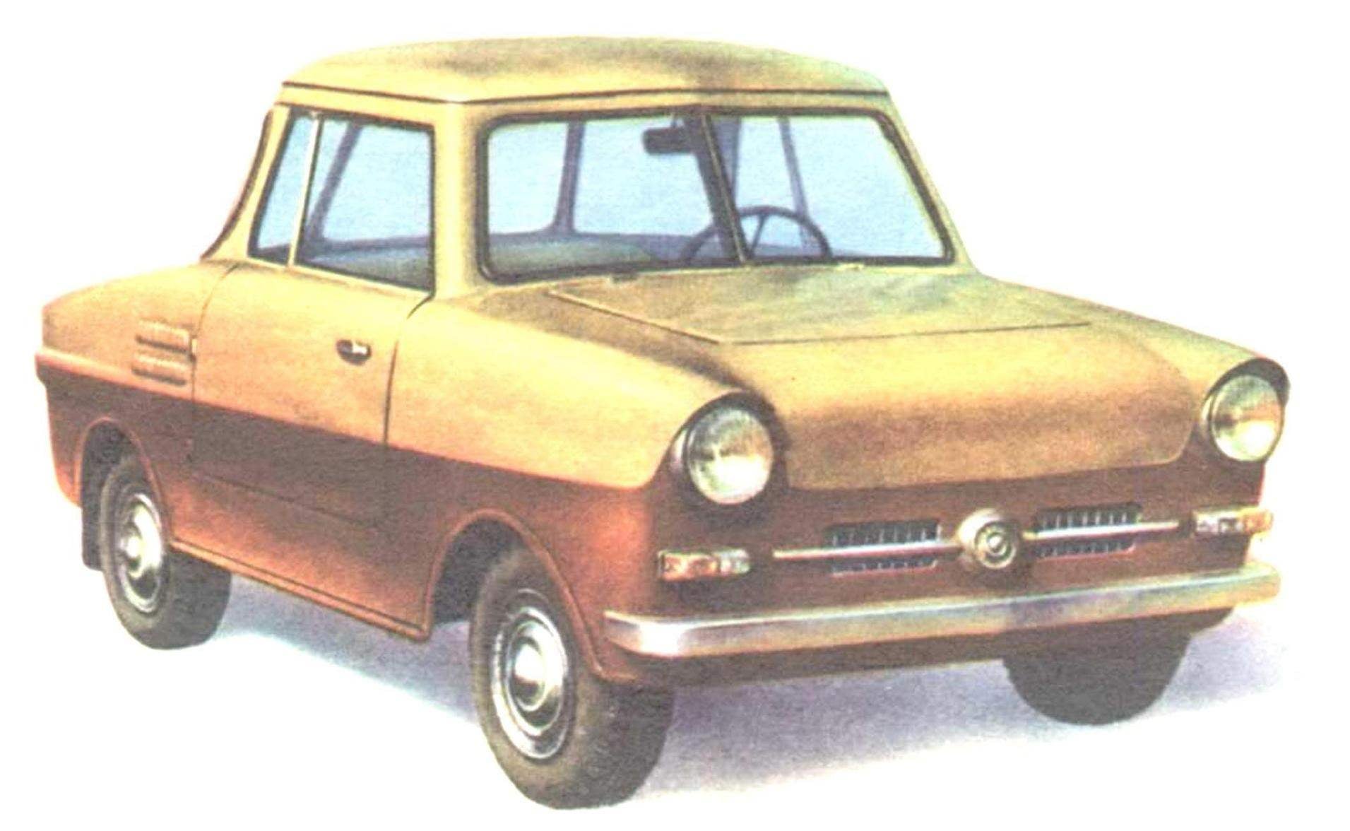
Body type — two-seater sports coupe, two-door; thinking that to car frame structure stiffness and strength its not critical, I decided to make a stacked wood frame, attached to glue and gussets (brackets). For covering plywood used in areas of small curvature with a thickness of 3 mm, and in areas having a large curvature (roof, sides, front of the hood), birch veneer with 0.5 mm thickness. Latest — ka kazeinovom to glue four layers, intersecting at an angle of 45-60°.

“MINI-LONDON” — original homemade car from Krasnoyarsk. COMPLEX CUSTOM SOLUTION: candle suspension, adjustable ground clearance, plywood body with wooden frame.

Fig. 1. The overall layout of the micro-car, only “Valga”:
1 — battery, 2 — “candle” front suspension, 3 — throttle, 4 — pedal unit (clutch and brake), 5 — shift lever, 6 — steering wheel 7 — arm reverse, 8 — engine, 9 — lever, kick starter, 10 — generator 11 — silencer 12 — main gear and reverse, 13 — driver seat, 14 — the lever of the Parking brake.

Fig. 2. Frame design: side view and top.

Fig. 3. Engine subframe: A — side view and top view, B— front view, back view.

Fig. 4. The location of the engine and the main transmission on the subframe (side view) and basic details:
1 — frame, 2 — front suspension, 3 — exhaust pipe 4 — a casing of forced cooling, 5 — generator, 6 — bolt tensioning device, 7 — cheek rear engine mounts, 8 — silencer 9 — rear Opera, 10 — front frame, 11 — rubber cushion, 12, 16 — mounting brackets rocker arms of the rear wheels and the main gear, 13 — gear, 14 — a safety shield, 15 — front bracket (“leg”) of the subframe.

Fig. 5. Cheek rear engine mounts:
right front view of the Assembly.

Fig. 6. Mount the subframe to the vehicle frame:
A — front view:
1 — front cross member frame, 2 — pad mounting rubber cushions, 3 — airbag, 4 — front cross member of the subframe;
B — back view:
1 — mount rear cushions, 2 — rear cross frame, 3 — airbag, 4 — rear cross member sub-frame.
Frame — tubular, with a Central spinal beam steel tube Ø 78 mm. Other details of steel pipes Ø 52, 33 and 22 mm, connected to gas welding. Inner surface of the pipe after welding were daubed with bitumen, the outer covered with primer GF-20. To frame ka four rubber pads from the car “Moskvich” is attached to the subframe (for convenience of Assembly and disassembly) of 50X50 mm area on it on two supports mounted engine. Main gear with reverse, balance weights on the rear axle, the muffler and the generator are mounted on the same subframe. Front bearing cover pipe sub-frame and fixed to it with two clamps, the back four bolts. The motor is pressed against the two plates, which also serve as parts tensioner of the chain connecting the secondary shaft with the main gear. The chain tension by turning the adjusting screw, which, being wrung out from a reference platform, raises the back part of the engine. The screw while rotating in a nut, welded to the shelf bottom right cheek. Before adjusting the chain tension loosened the pinch bolts which secure the cheeks to the back support. On the cheeks also fixed the muffler.
Main gear scooter T-200 M, she turned 180° so that the drive shaft is in the rear and the front differential. Under engine subframe to the main gear mounted by four bolts M8. To the right shelf of the sub-frame welded bracket, split nut M10, it screwed the adjustment fitting of the clutch cable. To the right rear leg of the subframe is welded to the side bracket platform for fixation of the gearbox drive cable.
Balance weights rear axle attached to the “feet” of the subframe bolts M10. The bottom of the main transmission is protected against damage by a safety shield made of sheet steel with a thickness of 3 mm.
MANUFACTURE THE BODY
The body frame is assembled from wooden bars of different sections (Fig. 7) with the brackets on the glue. Mount details additionally performed with screws, rivets and bolts. Generated when assembling the random cracks and fissures large values are not as easily sealed with mastic from wood sawdust with epoxy and not lose at the same strength. Portions of the surface of the body having a small curvature, sheathed with plywood of 3 mm thickness on glue and screws; lots greater curvature vyklevyvajutsja of birch veneer in temporary wooden or clay discs inserted in the appropriate places of the frame and removed after completion of the work. When the thickness of the veneer is about 0.6 mm would be the optimal overlay 4-6 layers, intersecting at an angle of 45-60°. The best glue for the job is thick casein. After drying, the panels are stripped off and are mounted on the screws with epoxy glue. The wheel housing is made of sheet duralumin with a thickness of 1,5—2 mm. To the frame attached with screws to the epoxy resin.


Fig. 7. The body frame of the micro-car, only and details:
A — side view, B — bottom view, B — top view, G — front view — back.

Fig. 8. Design improvised seat (the frame is welded from steel tubes Ø 22).

Fig. 9. Salon equipment:
1 — clutch 2 — brake pedal 3 — wall of trunk, 4 hand hand brake, 5 — the accelerator pedal, the 6 steering shaft, 7 — instrument panel, 8 — panel upper instrument sNDA, 9 — angled front windshield, 10 — Central front, 11 — wheel, 12 — door, 13 — selector lever transmission, 14 — driver seat 15 of the backrest, 16 — divider, 17 — control rod grip, 18 — pull brakes, 19 — pull switch, 20 — thrust reverse, 21 — lever reverse, 22 — seat 23 — block pedals.
The surface of the body is leveled by epoxy putty or mastic from sawdust with epoxy, and glued the body in a single layer of calico. Then primed, puttied nitroshpaklevok, carefully trimmed and stained with nitro in the desired color. My car is painted in two colors: the bottom chocolate, the top is light yellow. Areas of the body exposed to moisture (the bottom, front wall, wheel wells) coated with a hot paste made from a mixture of 50% bitumen and 50% linseed oil. Mount the body to the frame by eight bolts M10.
Doors exterior wooden frame double sided with a thin sheathing of plywood with a thickness of 3 mm. Inside are covered with black leatherette. Window frames metal door, U-shaped profile; you can use the air vents of the car UAZ-451. Vent Windows doors located in the rear light apertures are opened forward in the direction of the car and in the open position is retained with the valves.


The windshield is V-shaped, of two flat panels in a metal frame, fastened to the pillar. For its production used the three-layer windscreen of the car MAZ-200, crop to desired size were implemented as follows: template from cardboard with a wax pencil on the glass was applied to its contour on it with a diamond glass cutter on both sides were cut, in which glass was prostukivanii (also both sides) until solid hairline cracks along the contour. Then the cut area is heated by the candle flame to soften the middle layer of glass. Slightly stretching the edges of the glass, thin sharp knife the middle layer can be cut without much difficulty. After Stripping the edges of the glass with the Assembly in the rubber gasket inserted into the frame and secured it with a pad on the pillar. For all other glazing of light apertures I used plexiglass 5 mm thick rubber gaskets and metal framework.
Inside equipment body is made, as shown in figures 8 and 9, however, a possibility of application of other seats, instrument panel, steering wheel, etc. — it depends on the taste and financial possibilities of the Builder. But in all cases it is desirable to make the seats easy to remove from the salon is greatly simplify the installation work in the process of construction and operation of the vehicle.
DYNAMIC FACTOR D, %

On a body floor mounted clutch pedal, brake and gas, as well as levers gear shift and reverse. On the back wall between the seats are the levers of the decompressor and fuel corrector.
The walls of the interior are covered with black leatherette, ceiling — light gray; seat covered with mats of rubber and covers made of soft leatherette.
Builders that do not possess the skills to perform shipovyh connections (“vpoldereva” and “dovetail”), we recommend you to use the docking bars of the framework with crackers and gussets (brackets) to the epoxy glue. Mounting brackets — nails “in bend” and screws.
V. HASSAN, engineer


