For water tourism enthusiasts who live far from large bodies of water—rivers, lakes, and seas—setting out on a voyage means first getting both themselves and their craft to the “big water.” That is why the craft must be mobile by design: foldable or take-apart.
I faced a challenging task: to build a capacious, reliable, stable—even seaworthy—craft of small mass that could be transported in a railway sleeping compartment and on public transit. Although it is theoretically possible to reach the port of the “five seas,” getting to any of them—even by car—is far from easy. Besides, a car forces you to plan a closed route (you have to come back to it), which is not always convenient.
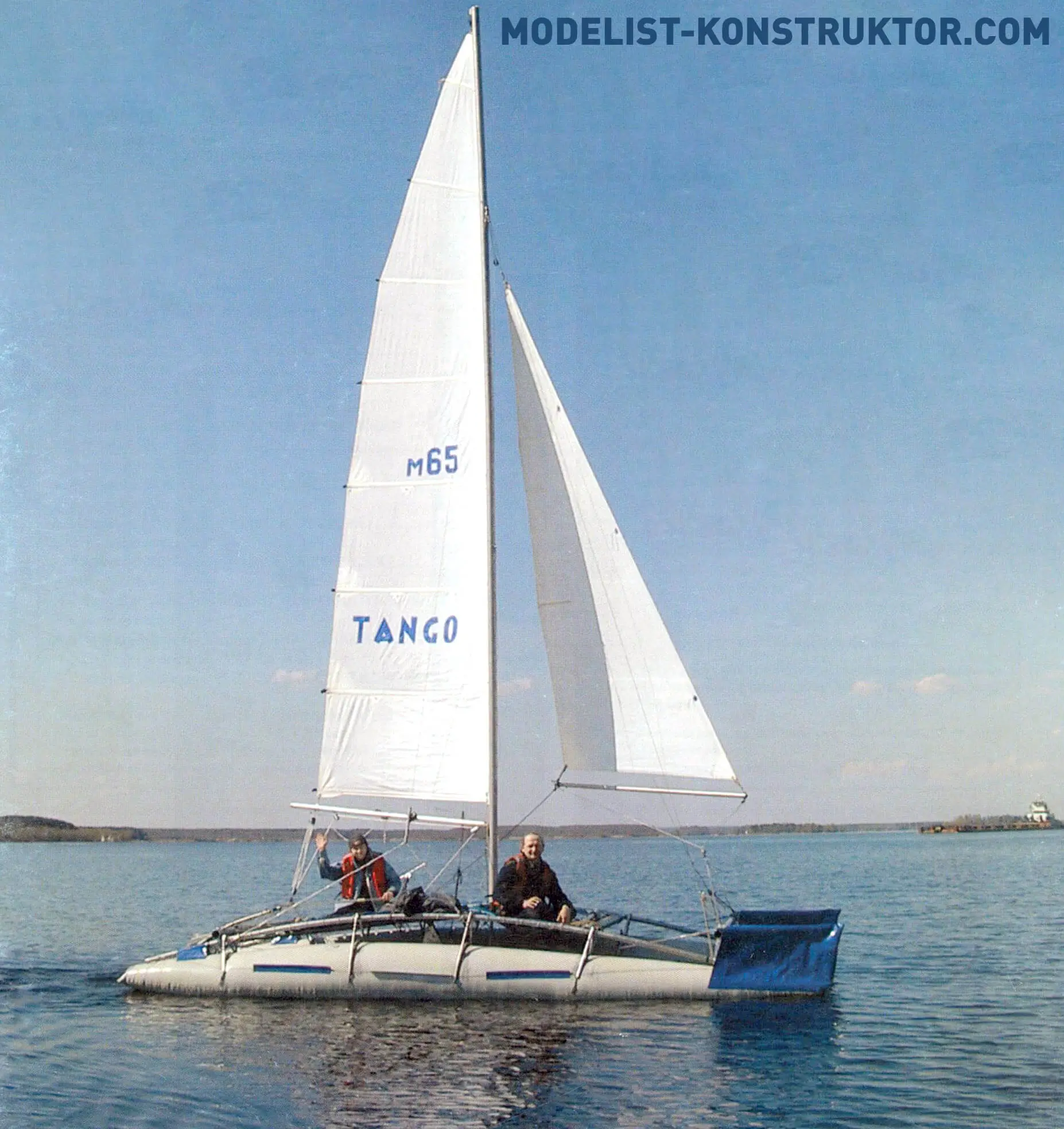
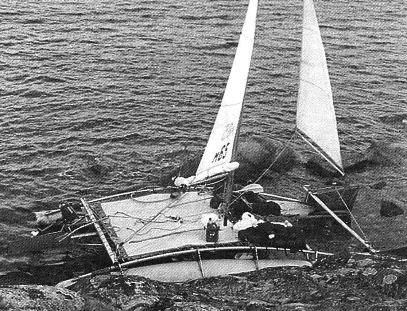
So I concluded that I needed to build a take-apart sailing catamaran on inflatable hulls. The idea is hardly new (I had already built more than one), yet with a creative approach each subsequent design turns out original.
Starting the story about the catamaran with inflatable hulls and a Bermuda-sloop rig, I should note that it was designed and built with the aim of using modern, yet widely available and relatively inexpensive materials, relying on both my own experience and that of others.
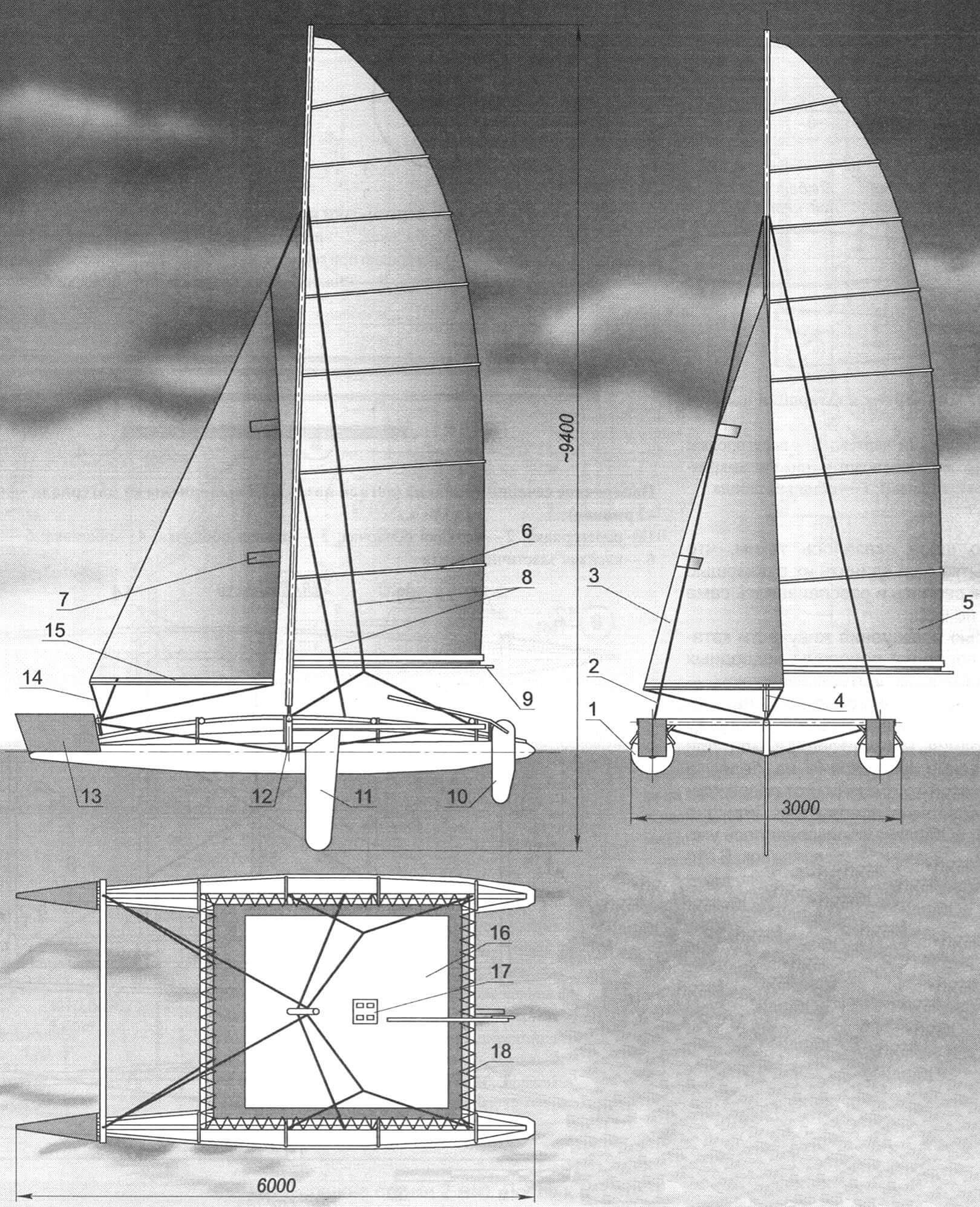
1 — hull (2 pcs.); 2 — forestay of the mast (2 pcs.); 3 — jib; 4 — mast; 5 — mainsail; 6 — mainsail batten (8 pcs.); 7 — jib batten (2 pcs.); 8 — mast shrouds (4 pcs.); 9 — main boom; 10 — steering gear; 11 — centerboard; 12 — catamaran structural frame; 13 — bow bulwark (2 pcs.); 14 — jib sheet (Kevlar line); 15 — jib boom; 16 — deck (Ferrari fabric, s0.5); 17 — sail and catamaran control station; 18 — deck lacing
Note.
* In the side view the port hull is omitted; the sails lie in the centerline plane.
** In the top view the sail plan is omitted.
*** In the front view the sails are shown trimmed for a run.
The catamaran was constantly upgraded. Shortcomings that appeared during river expeditions (sometimes several hundred kilometers long) were corrected during the off-season. The design, however, was refined without radical rework, because the vessel was fundamentally designed and built properly.
The catamaran is equipped with nearly every type of water propulsion: sails, an outboard motor, and a paddle. The sail is, of course, the primary mover. The outboard is used only in a dead calm or headwind, and the paddle is employed in shallow water—either as a pole or as a sweep for maneuvering in tight quarters.
The catamaran’s hulls (there are two) are inflatable, twin-chamber structures with a longitudinal partition and an additional skin over the lower portion. They are cut and bonded from Ferrari fabric only 0.5 mm thick, density 650 g/m², 2700 mm wide in the roll—a synthetic (PVC) airtight film with a textile base. The material is quite strong, and its outer face is very smooth.
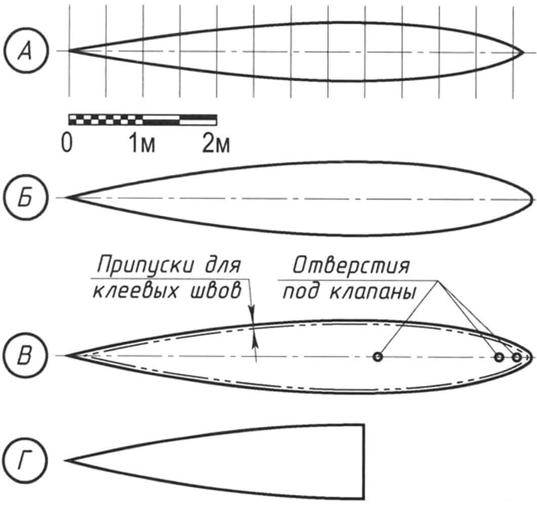
A — lines plan; B — partition; C — upper and lower skins (lower skins are cut without openings); D — bottom sheathing
Each hull is bonded with Urmono adhesive from three separately cut panels whose patterns are practically identical (allowance for seams aside).
Two panels form the hull skins, and the third acts as the partition that creates two chambers in the normal (inflated) state.
“Normal” means both chambers are inflated and the shells (upper and lower) are airtight. The partition is then in a “neutral” position. If one shell is accidentally damaged and air escapes from its chamber, the partition, pushed by the pressure from the remaining chamber, shifts toward the damaged side once that chamber is topped up.
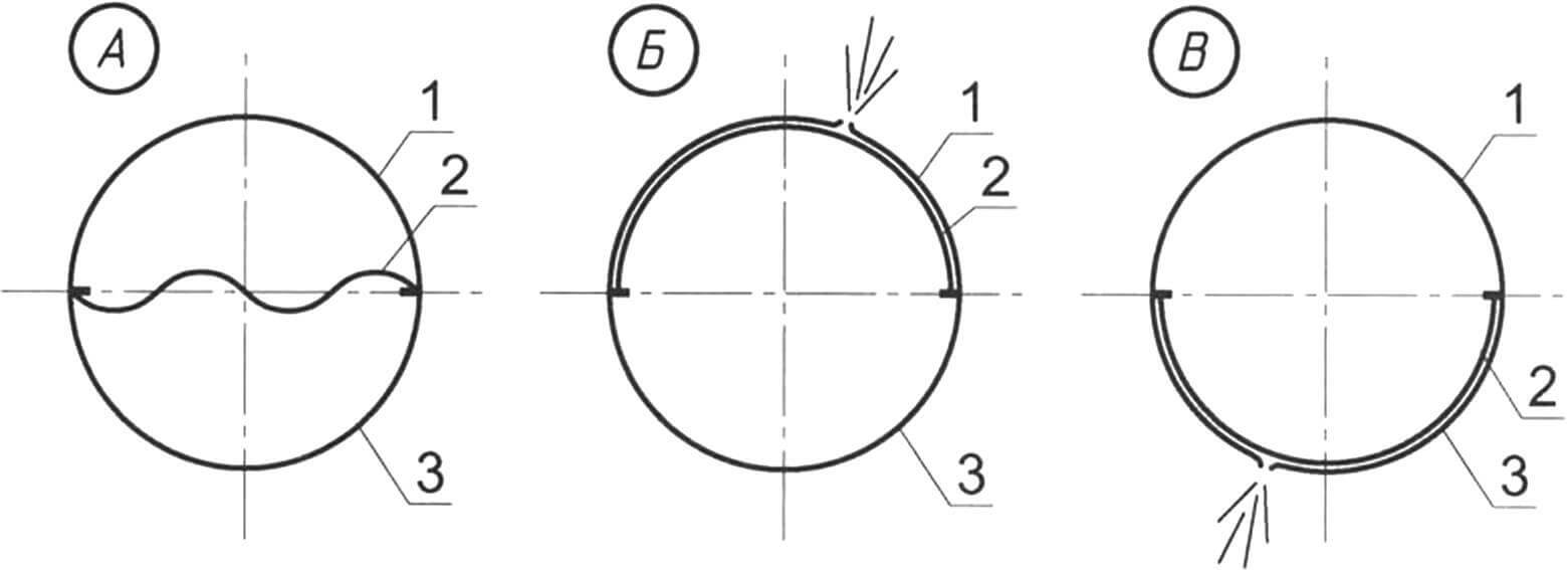
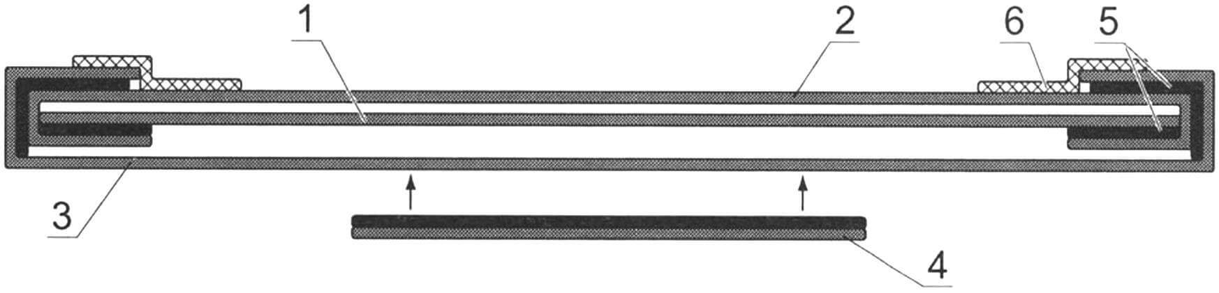
1 — upper (above-water) skin; 2 — partition; 3 — lower (underwater) skin; A — neutral partition position with airtight skins; B — upper position when the above-water chamber skin is damaged; C — lower position when the underwater chamber skin is damaged
There is also a fourth panel. It sheaths the fore bottom of the hull up to the midship section. The hulls are spindle-shaped—smooth curves and circular sections along their entire length, which ensures low hydrodynamic drag. Approximately two-thirds of the way aft from the bow (slightly past the mast) lies the midship section where the center of buoyancy and the point of application of Archimedes’ force are located. One important detail: the upper chamber is 200 mm shorter than the lower one. At that point the “tail” of the partition is bonded only to the upper skin. Extra pads for the air valves are attached here as well—one before the partition, one after.
Each hull has three valves. Two aft valves (already mentioned) serve both to inflate the hull before launch and to release air when rolling it up. The third valve, located on top near the midsection, is used to pump up the upper chamber from the deck if the lower chamber is damaged while underway. In that case not only the catamaran but also the damaged hull stays afloat.
A few words on the fabrication process—cutting and bonding the panels into hulls.
1 — partition; 2 — upper skin; 3 — lower skin; 4 — sheathing; 5 — adhesive seams; 6 — self-adhesive elastic tape
We mark out the panels according to the lines plan by rolling the fabric out on the floor and securing it with double-sided tape. Stepping back from the longitudinal edge by a quarter of the hull circumference at midship, we draw the centerline—ideally along the fabric grain. Along that line we lay off the hull generator length. At the specified stations we compute the circumference, set off one quarter of it to each side of the centerline, and connect the resulting points with a fair curve using a flexible batten.
Following the layout, we cut the first blank with ordinary scissors (this will be the partition) and then another for the second hull. Placing one of the patterns on the fabric, we cut the next blank (upper skin) with a 20 mm allowance, then another for the other hull. The third pair is cut from the last blank with the allowance increased by another 5 mm.
Bonding starts with the upper skin and the partition after thoroughly cleaning the mating edges with white spirit. The upper skin lies underneath. The partition tail is bonded to the upper skin, stopping 200 mm short of its end.
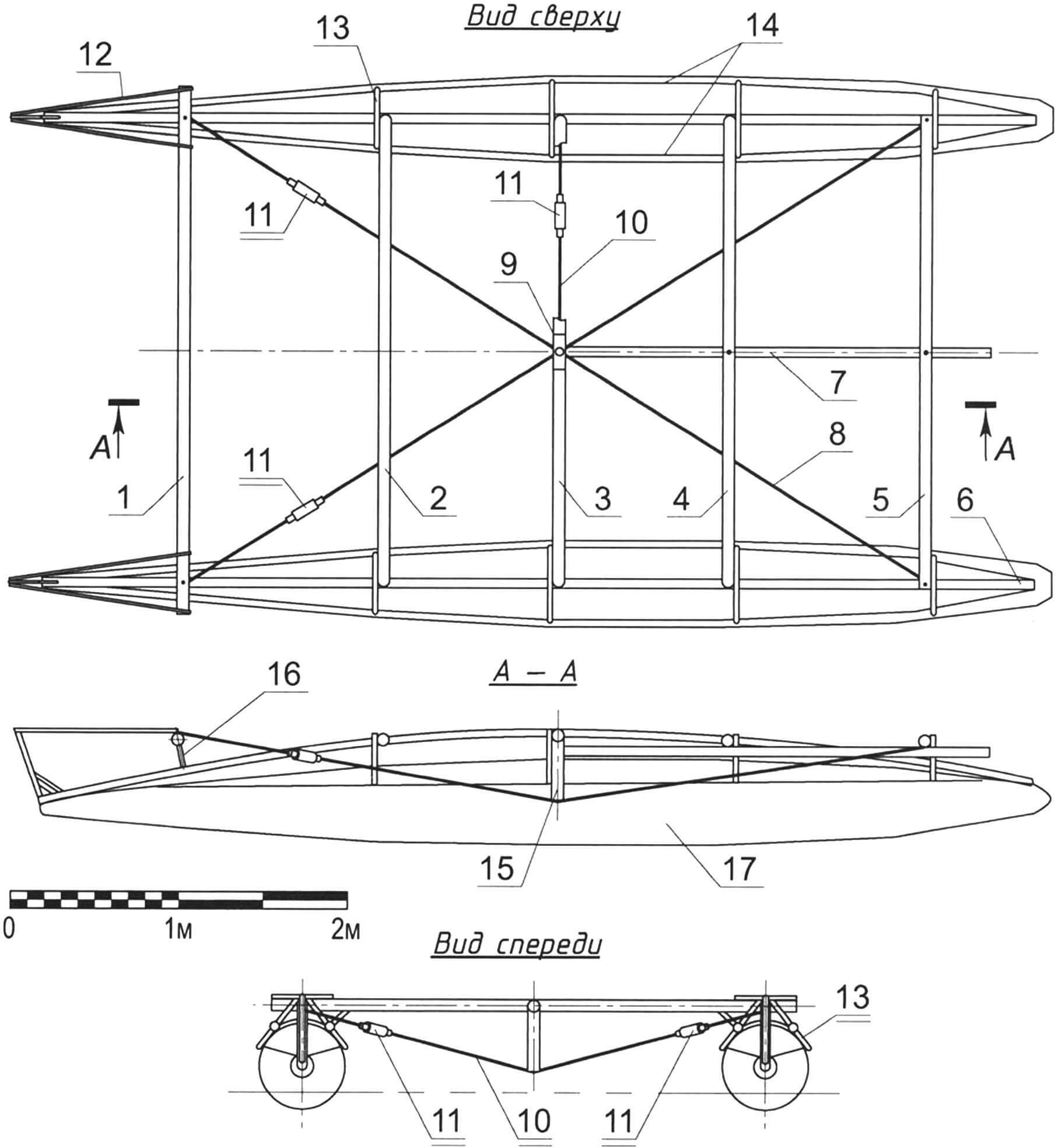
1 — bow beam (Ø60×2 tube); 2 — forward deck beam (Ø80×2 tube); 3 — mast partner beam (Ø80×2 tube); 4 — middle deck beam (Ø80×2 tube); 5 — aft deck beam (Ø80×2 tube); 6 — stringer (Ø60×2 tube, 2 pcs.); 7 — longitudinal cantilever beam (Ø60×2 tube); 8 — diagonal guys of the spider strut (Ø3 cable, 2 pcs.); 9 — clamp/bush for the cantilever beam; 10 — transverse “spider” cable (Ø3); 11 — turnbuckles; 12 — bulwark frames (Ø25×1.5 tube, 2 pcs.); 13 — cradles/frames (Ø25×1.5 tube, 8 pcs.); 14 — hull tie cables (Ø2, 4 pcs.); 15 — strut (spruit); 16 — bow beam pillar (Ø60×2 tube, 2 pcs.); 17 — hull
After applying adhesive we let it tack off for about 20 minutes at room temperature. The allowances of the upper skin are then folded over onto the glued edges of the partition, carefully avoiding wrinkles. Heating the seams with a heat gun, we roll them down or clamp them in any convenient way.
Next, we flip the assembly and lay it on the lower skin, smooth side down (this forms the underwater shell), and repeat the bonding process.
Finally, to guarantee airtightness, we add a 50 mm strip of self-adhesive polyethylene tape over the last seam.
The seams proved so strong that attempts to pull them apart with pliers only tore and delaminated the fabric itself, not the joint.
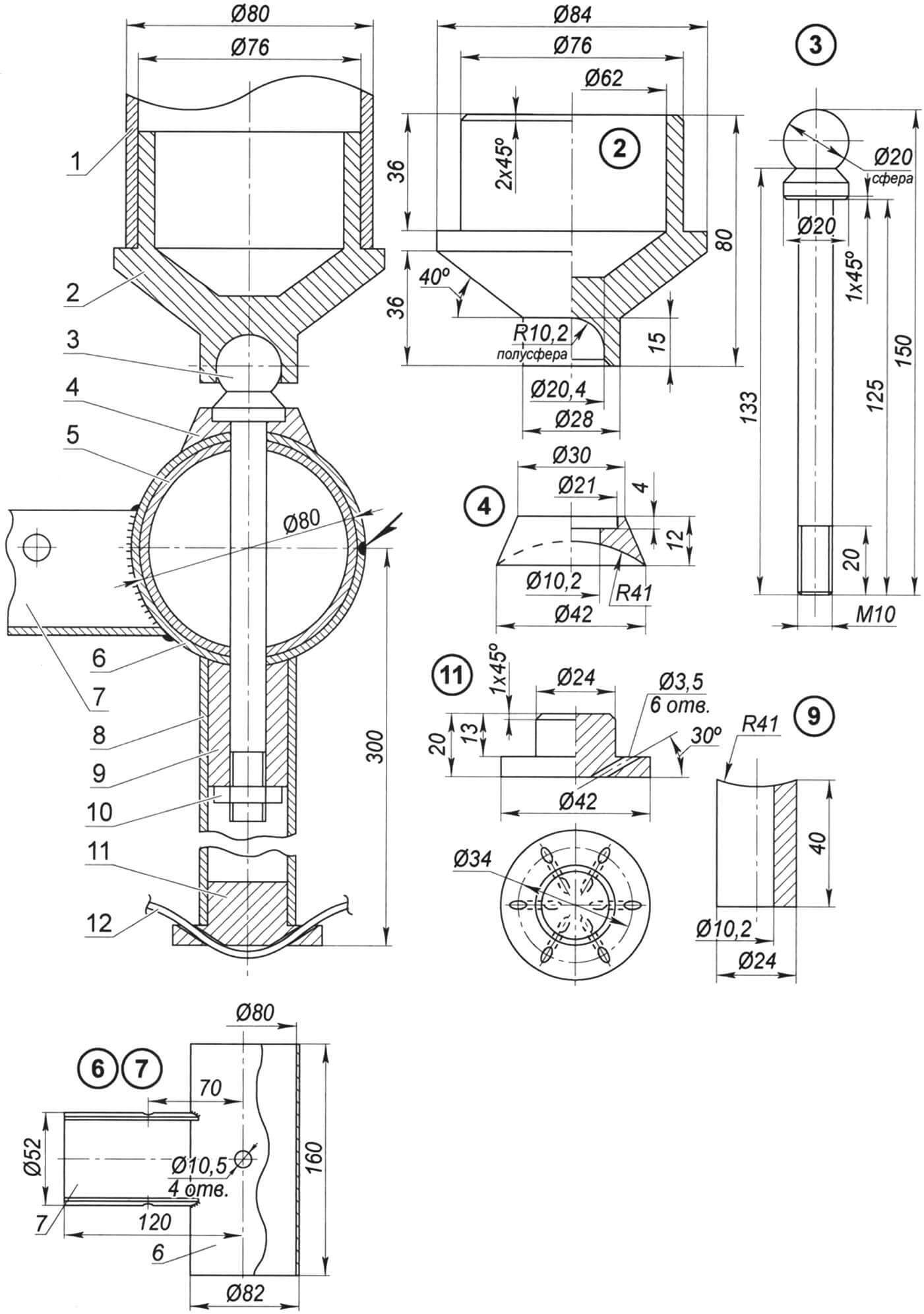
1 — mast (duralumin, Ø80×2 tube); 2 — mast heel (duralumin); 3 — step (special M10 bolt, stainless steel); 4 — pad (shoe) (duralumin); 5 — mast partner beam (duralumin, Ø80×2 tube); 6 — bush (stainless steel, 1 mm sheet, welded into a tube); 7 — collar (stainless steel, 1 mm sheet); 8 — strut (duralumin tube Ø28×2); 9 — mounting sleeve (duralumin); 10 — strut fastening (M10 nut, stainless steel); 11 — “spider” (duralumin); 12 — cable (stainless steel
To improve survivability, the forward halves of the underwater chambers are clad in an extra “sheathing” layer of the same fabric. It protects the lower skin from abrasion in shallow water or when the catamaran is hauled ashore, and to some extent from underwater hazards and the bottom. The sheathing was bonded to the finished, inflated hull; at the same time pockets for the stringers and sleeves for the cables were glued on.
Structural frame. Although the catamaran rests on hulls akin to inflatable mattresses, it still has a structural framework like most craft. The frame can be described as a flexible–rigid, or beam-and-cable, system.
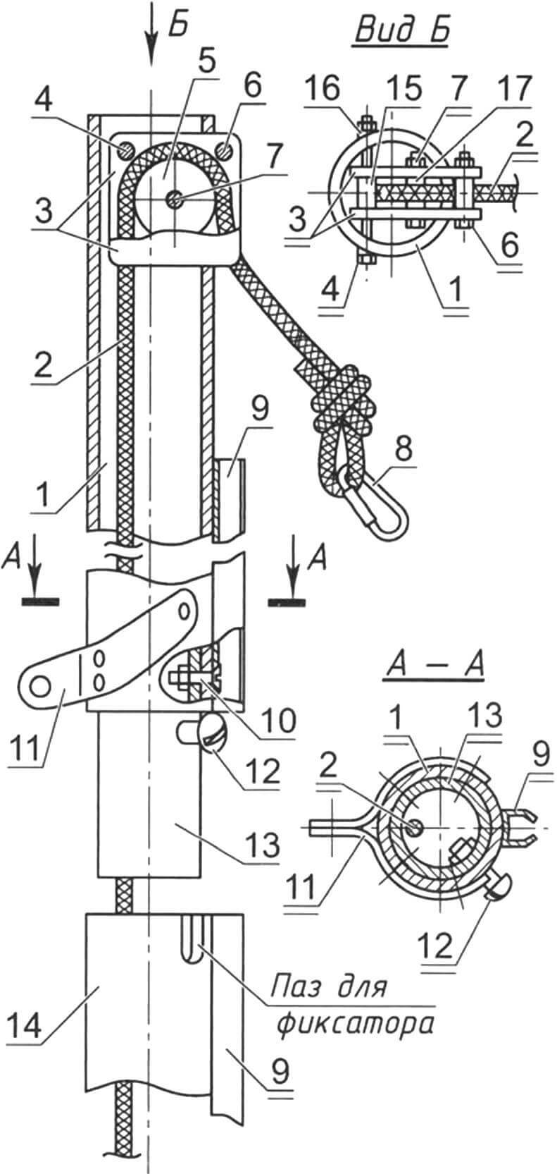
1 — top section (royal topmast); 2 — halyard (10 mm nylon line); 3 — sheave cheeks (2 mm duralumin sheet); 4 — block mounting on the masthead (M6 bolt with beveled washers and spacer sleeve, L90); 5 — sheave (duralumin); 6 — halyard stop (M6 bolt, L30 with spacer sleeve); 7 — sheave axle (M6 bolt, L30); 8 — snap hook; 9 — sail track (duralumin, U-profile with turned-in flanges); 10 — fasteners for the sail track and spigot (M4 flat-head bolts); 11 — shroud tang (1 mm steel, 2 pcs.); 12 — section and track position lock (two M4 bolts); 13 — spigot (duralumin tube Ø76×1.5); 14 — penultimate mast section (topmast); 15 — spacer sleeve (duralumin tube Ø8×1, 2 pcs.); 16 — beveled tubular washer (duralumin); 17 — spacer washer (nylon, 2 pcs.
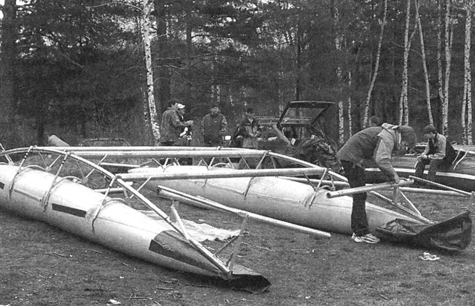
Before detailing the frame members, note that all of them were designed with a single principle in mind: they must be allowed into a passenger railcar or even city transport. Practically, that meant every long element was divided into 2200 mm segments (or the shorter remainder). For example, the 8 m mast is assembled from four sections: three 2.2 m pieces and one 1.4 m piece. The joints rely on an internal sleeve with two bolts, and the relative orientation is fixed by a bolt in the sleeve engaging a slot in the section. The slots and bolts in one section are rotated 90° relative to those in the next.
The longitudinal frame members—stringers—are made of duralumin tube 60 mm in diameter, 2 mm wall. After their sections are joined and the stringers set onto the cradles, the ends of each stringer are cinched with two cables running in sleeves (special seam-pockets) along the hull sides, shaping the members into a shallow arch. These same cables pass through slots at the bottoms of the cradles, tying the frame to the hulls.
The cradles (frames) under the stringers resemble small trestles and are made of 25 mm duralumin tube with 1.5 mm wall. The tops of the legs are clamped by a collar inserted into the stringer and tightened with a screw. Midway down, the legs are joined by a tie bar curved to the hull radius; this forms the bearing surface that transfers loads to the hull captured between the legs. A shaped slot is cut in the lower ends to receive the cable, linking the hull to the frame and locking it in place. The forward and aft cradles are slightly smaller than the middle ones.
The stringers are joined by a bridge of several transverse beams. The forward (bow) beam uses the same 60 mm tube as the stringers, while the others are 80 mm duralumin tubes. To prevent a head sea from washing over, the bow beam is raised above the stringers on pillars, whereas the next three are butted directly to the stringers. The aft beam is laid atop the stringers, again to lift it over the wave tops. Strictly speaking, calling it an “aft” beam is conventional—it is simply the rearmost one because there is no beam right at the stern. A longitudinal cantilever beam supports the steering gear and outboard instead. Even if a wave reaches it, the hydrodynamic drag is minor, so the speed barely drops.
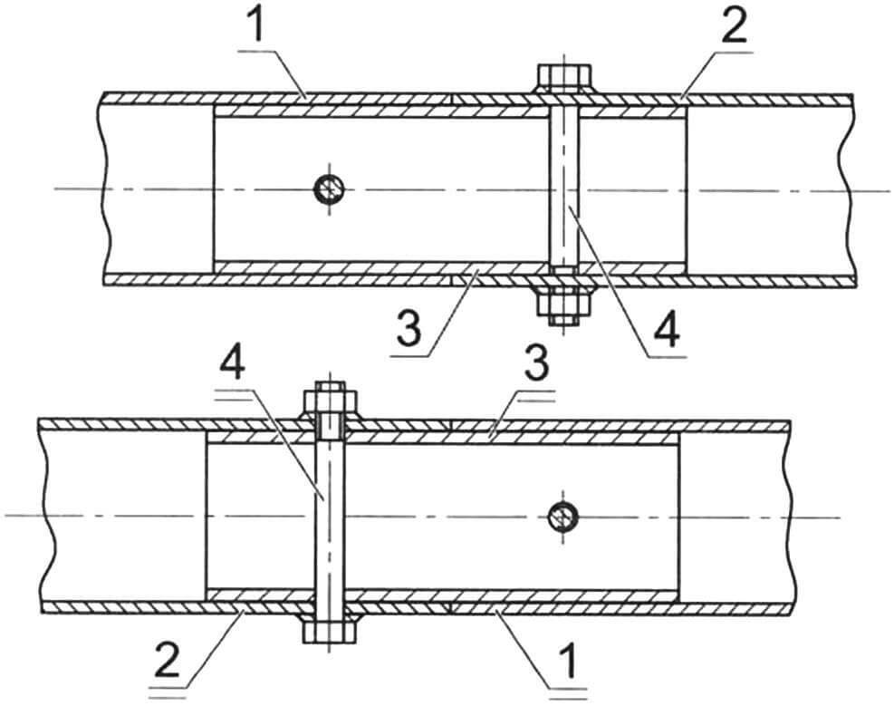
1 — first section; 2 — second section; 3 — sleeve; 4 — fastener (M8 bolt with two custom “tubular” washers, 2 sets)
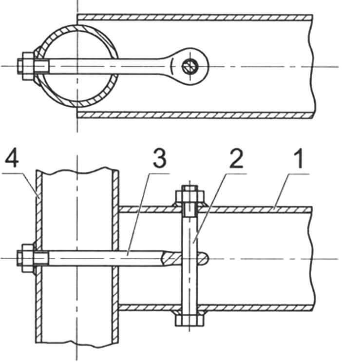
1 — beam; 2 — pin (M8 bolt with two custom “tubular” washers); 3 — fastener (M8 bolt with eye head and custom “tubular” washer); 4 — stringer
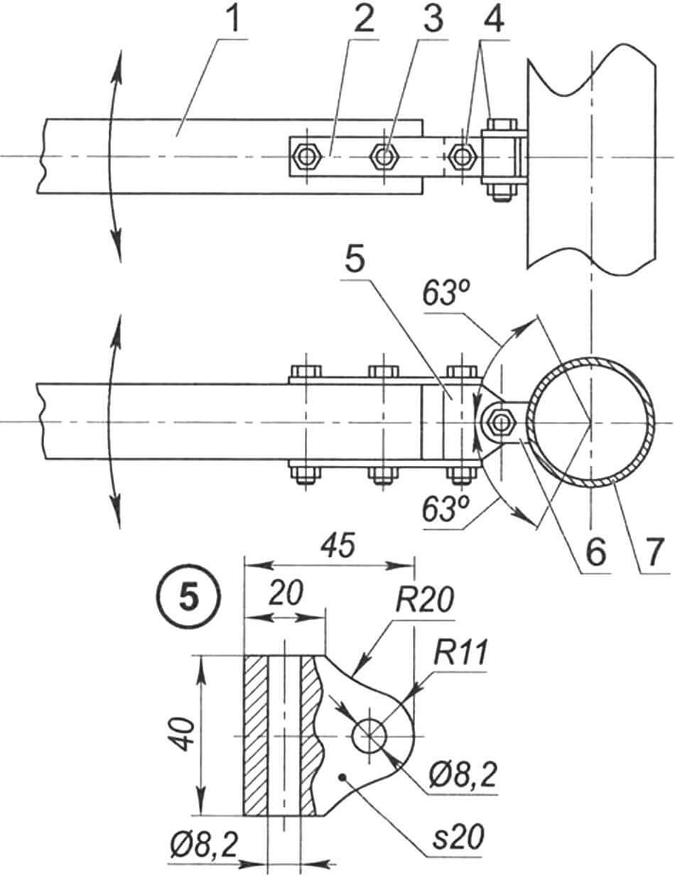
1 — stem (Ø25×1.5 duralumin tube); 2 — brace; 3 — eye (3 mm steel plate); 4 — stringer; 5 — cable; 6 — clamp with eye (1 mm steel); 7 — spar (Ø20×1 duralumin tube, 2 pcs.); 8 — forward beam; 9 — beam pillar (Ø60×2 tube); 10 — hull
1 — boom; 2 — strap (duralumin, 3 mm sheet, 2 pcs.); 3 — boom fastener (M8 bolt with nut, 2 pcs.); 4 — universal joint pins (M8 bolt with nut); 5 — block; 6 — clevis; 7 — mast
The beams are additionally braced to the cradles that support the stringers. Each beam consists of two pieces: a 2.2 m segment plus a remainder (which differs between bow, intermediate, and aft beams).
The mast partner beam carries the greatest load. Like the others, it is sectional, and it was reinforced with a device called a sprit: a vertical strut beneath the beam held by three guys. Two diagonal guys tie the bow of one stringer to the stern of the other, and a third transverse guy runs under the beam, its ends anchored to the stringers. The cables pass through holes in a plug (the “spider”), redistributing part of the mast-and-sail load from the beam to the stringers.
The sails—main and jib—are commercially made, so I will skip their fabrication. For earlier projects I sewed my own, guided by specialized literature and by articles in the Modelist-Konstruktor magazine (issues 6–7/1977 and later 5–6/1999).
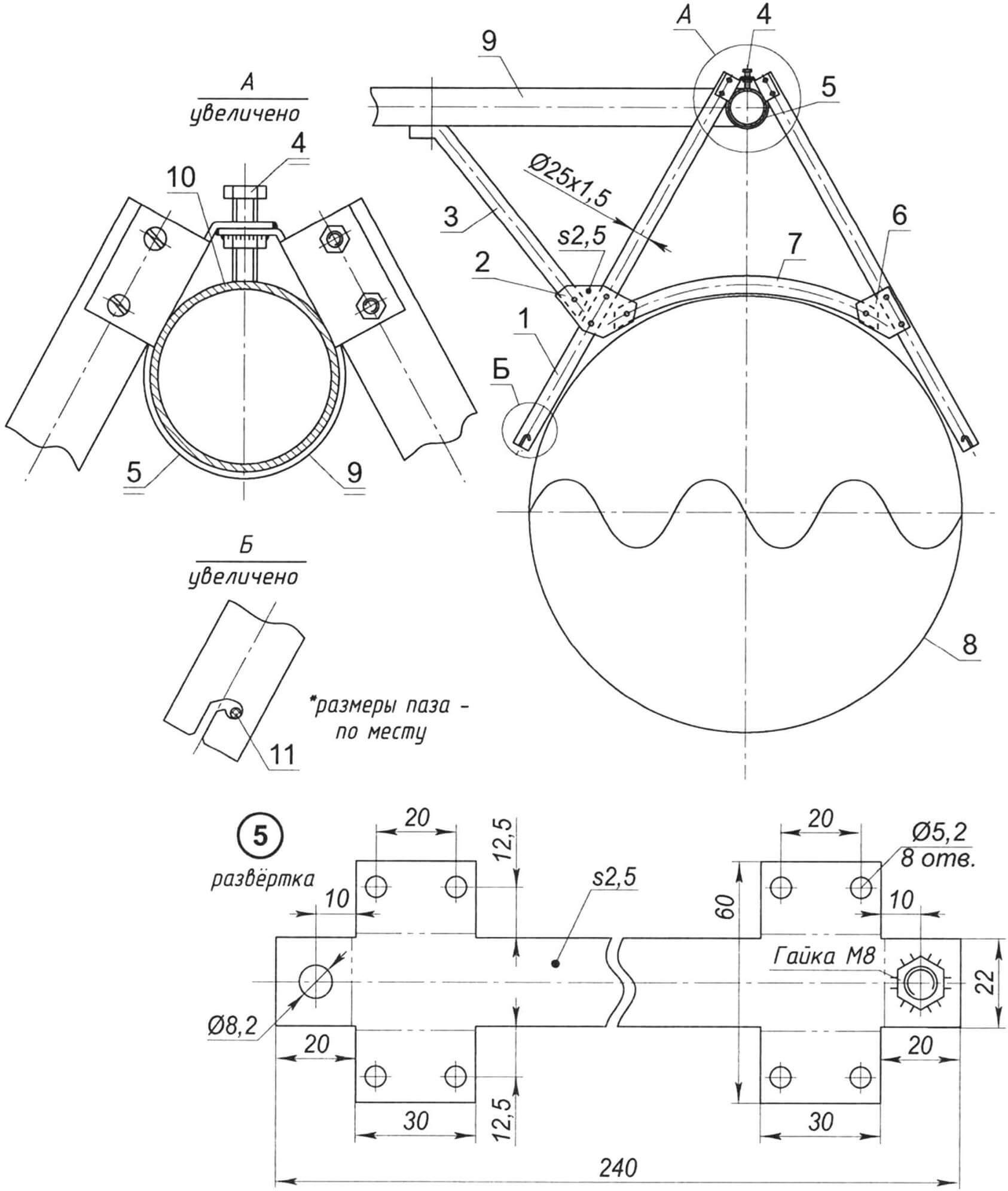
1 — leg (2 pcs.); 2 — gusset plate (duralumin, 2 mm sheet, 2 pcs.); 3 — brace of the transverse beam; 4 — stop (M8 bolt); 5 — clamp (stainless steel, 2.5 mm sheet with M8 nut); 6 — strap (duralumin, 2 mm sheet, 2 pcs.); 7 — tie-bar support; 8 — hull; 9 — transverse beam; 10 — stringer; 11 — cable
I did, however, fabricate (more precisely, bond) the deck myself using the same technology as for the hulls (it is also Ferrari fabric). The deck is a rectangular single-layer panel edged with a double-folded strip of the same material (in a contrasting color). Around the perimeter the edging is left unbonded to form narrow sleeves; during assembly, small-diameter aluminum tubes slide into them. Along these tubes, small holes about 150 mm apart are melted with a hot soldering iron so the deck can be laced to the stringers and beams. The mast opening is reinforced with the same fabric. Between that opening and the aft deck edge, centered, a stainless plate with several plastic cam cleats—the sail and boat control cluster—is riveted on.
The mast is made of an Ø80 mm, 2 mm-wall duralumin tube. As already mentioned, it breaks down into four sections: the lower mizzen mast, above it the topmast and topgallant, and finally the royal mast. A heel sleeve is pressed into the bottom section so it can stand on the sprit step, and slightly higher there is a hole for the halyard exit. The mast is stayed with four shrouds whose upper ends attach to a tang 5.5 m above deck. The lower ends of the forestay pair fasten to the ring-head bolts that tie the forward beam to the stringers. The aft shrouds split: one branch hooks to the bolt joining the mast partner beam to the stringer, the other to the bolt securing the stringer to the aft beam.
The mast is raked aft 5–12 degrees. A sail track is attached along its entire height (to every section) for the luff of the mainsail into which the bolt rope is sewn. A block for the halyard is mounted on the royal masthead, and slightly below it a block on a tang handles the jib sheet.
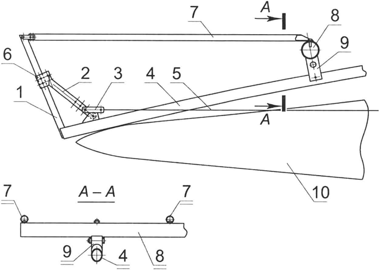
The rudder and centerboard share the same design and material: 1 mm duralumin sheet. Their spars are bent into channel sections and fastened with countersunk rivets. The rudder mounts on the aft end of the longitudinal cantilever beam. The tiller is fairly long and made sectional with a universal joint for easier handling. The centerboard is attached to the same beam, closer to its forward end.
To improve seaworthiness, each bow carries a spray deflector consisting of a frame and a cover. The frame is a stem mounted at the front end of the stringer, with spars tying its tip to the forward beam. The cover is a triangular bag sewn from the same Ferrari fabric. Its lower edges have sleeves into which the cables that cinch the stringer ends are threaded, pulling the cover snug against the hull sides.
I inflate the hulls with an ordinary foot-operated rubber boat pump (“frog”). You can also use an automotive electric pump powered from a car’s electrical system if you haul the boat by car. I never measured the pressure, but I know it’s sufficient when, standing on a hull myself, it barely deflects.
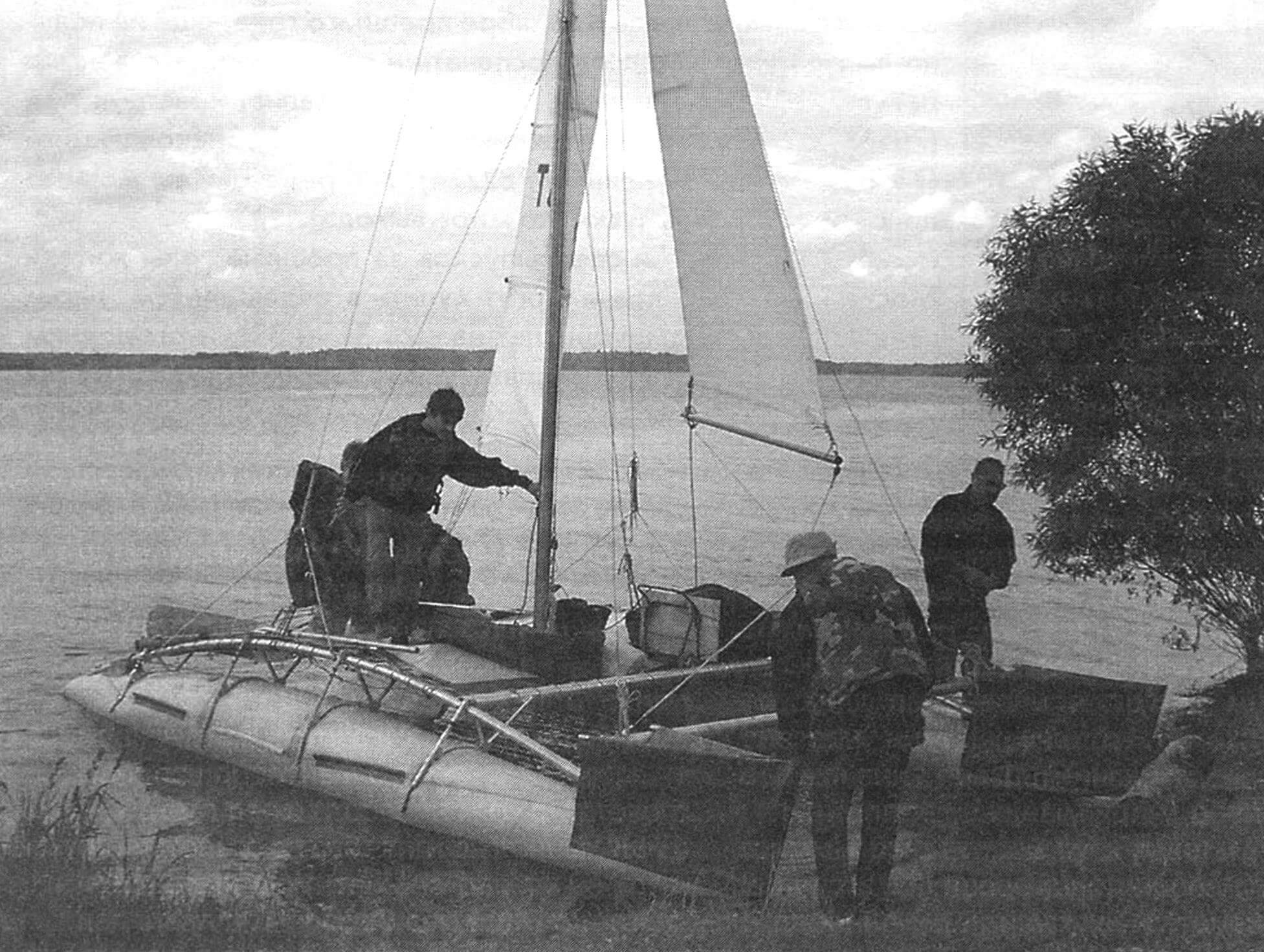
The catamaran weighs about 165 kg. When disassembled it fits into four packages, each within the limits accepted on public transit and in passenger railcars. Each package weighs only a bit more (or less) than 40 kg, so two people—or even one—can carry it. Three people can assemble the catamaran in roughly three hours.
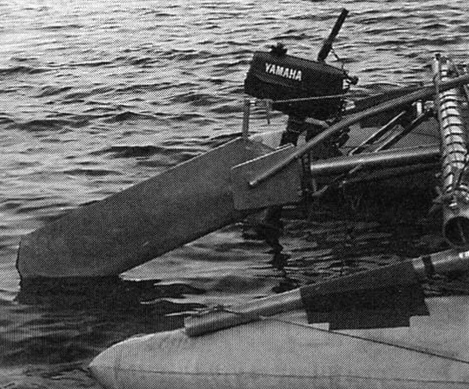
I recently bought a Yamaha 2 hp outboard for the catamaran. I built a small, simple subframe for it and hinged it to the aft beam slightly to port of the rudder.
K. TAGILTSEV
Recommend to read
 “Boat”-snowmobile
I was born and raised in a region where the ground stays under a thick snow cover for most of the year — so it’s no surprise that people consider this place the homeland of Ded Moroz.... GLASS PLIERS
If a sheet of glass cut by a few millimeters, then break off the edge you better not side groove of the glass cutter, and pliers. In this strip of glass is often separated from the sheet...
