The main tasks that were solved in the design of the proposed model was maximum simplicity of construction, strength of all the main elements, technology, and the creation of a small unit mass. Test the constructed model showed that all these problems were solved adequately — and this despite the use of only domestic materials (balsa needed only for rudders). In addition, the flight once again confirmed that the parasol is very good for training purposes, especially in calm weather. Under such atmospheric conditions, the model literally conquers the pilot for his ability to slow steady flight and good response to rudder.
The basic data model
Wing area……………….33,6 dm2
The area of the city on………………………7,9 dm2
Total weight…………………….1900 g
Specific load of 56.5 g/dm2
Training RC model airplane under the engine a working volume of 6.5 cm3.
The fuselage Assembly from the chassis and keel:
1 — front bulkhead (plywood s4), 2 — panel engine compartment side reinforcement (plywood s2), 3 — trim, wedge-shaped, defining Vegas the axis of the engine down (solid wood: beech or hornbeam), 4 — front bulkhead (plywood s3), 5 — “the canister” fuel tank (paper in three layers based on epoxy resin), 6 — prosperous additional (plywood s3), 7—front wing (switching from four layers of plywood s1 epoxy resin), 8, 10, 12 — frames of the forward fuselage (plywood s3), 9 is the covering of the front fairing (pre-formed part made of plywood s1; put in place only after trimming the upper corners of the side panels), 11 — stringer top (pine rack 4×4), 13 — imitation polycarbonate cabin compartment (plywood s1) 14—prosperous rear fairing (balsa s3) 15 — filler rear fairing (melkosortnyj packing foam), 16 — trim fairing (Whatman epoxy resin), 17, 18, 28 — the frames tail section (plywood s3) 19 — inserting finger (Linden B5), 20 — edge of the keel front (pine rack 5×5), 21 — filler keel (foam melkosortnyj packaging, or grade SS-4-40) 22 — fin tip (Linden s5), 23 — rudder (balsa medium density s5), 24 — boss (Linden) 25 — “crutch” (plywood s3), 26 — torsion drive elevators (cabanilla part), 27 is the window for withdrawal of the control rod of the rudder, a 29 — plating bottom (plywood s 1), 30 — sheathing Board (plywood s1), 31 —crossbar power wing stand (aluminum), 32 — M4 screw with large steel washers, 33 — pin for rubber straps, landing gear (aluminum knitting needle Ø 4), 34 — pad remote (plywood і2), 35 — area Logement (B2 plywood with a cross grain direction “shirt”), a 36 — Klondike (plywood s2), 37 — stringer bottom (pine rack 4×4) 38 — pad ring (plywood s), 39 — motor plate (single curved part, cut from plywood s10), 40 — rack chassis (hardened aluminum s3), 41 — wheel (standard), 42 — lining reinforcement of the upper stringers (select high quality plywood s1,5…2).
A small mass of the apparatus, causing a low on the load bearing surface, at the same time gives the effect of a high thrust-weight ratio even when the engine of average power. Thus the pilot in all situations remains the possibility to use reserves, the thrust of the power plant to bring the model of the critical provisions. All primary flight, usually carried out on “polegate” in which “two stroke” reminds her in a low rumble working four-stroke motor. The only thing that “doesn’t like” the parasol is a dramatic aerobatics in gusty wind — the behavior of the machine becomes unpredictable. However, such weather is generally not well suited for an educational-training flights, so the “whims” of our model can be considered “excusable”. Just not to want her that is heavy and large aerobatic machines.
The fuselage model is a relatively simple design based on the use of hard plating carrier aircraft plywood thickness of 1 mm. With a neat Assembly with no visible gaps between the parts and with carefully taped seams, turns easy, very durable product. The main requirement is to use high-quality plasticized epoxy resin in order in extreme situations, the fuselage was not split at the seams.
Work on the fuselage begins with the manufacture and processing of exactly the right size wing struts (blank glued together from four layers of 1 mm plywood, resulting in excellent high-strength material, incomparable mechanical characteristics with conventional 4-mm plywood), and the width of the vertical plates of the uprights must be at least 20…25 mm.
The next step is to manufacture the side panels. First of all mark the pattern of the side plates, after which they are glued pine stringers with a cross section of 4×4 mm (at this stage the patterns should have low stocks on all contours). In places of pass of struts of the wing stringers are cut, and they themselves stand are glued in place. Then throughout the nasal part of the upper stringers, cut the uprights of the wing, increasing the thickness of overlaying a narrow strip of plywood in the thickness 1,5…2 mm (the width of the ribbon should be the same as the stringer, that is equal to 4 mm).
The next step is to assemble the forward fuselage with frames, which are located up to the level of the trailing edge of the wing, and cut out of 10 mm plywood notched plate of the motor. During this operation, one side can be clamped to a flat Board-stocks to avoid twists and leash the entire fuselage. To control before applying the glue you need to get the fuselage together — the stringers must accurately be aligned with each other. If not, check the manufacturing precision of the front frames and, if necessary, or modify them, or run over, more accurately.
Getting ready node front part of the fuselage, you can do it “stuffing” auxiliary units fuel tank mounting and fixing elements of the side of the radio. Note that on the horizontal Motorama this will be quite simple. Vegas the same axis as the engine will be set due to the wedge-shaped linings. In addition, this technique will facilitate and adjust the angle of Vicosa, which will be enough to change these wedge-shaped pads, not cut or increase the regular mount. Mounted at the same time and of the details relating to the lodgement of the rack mount chassis.
Then the rear of the side panels must be pulled together, until the landing of the stringers in the grooves of the rear lugs of the fuselage. This can be done in two ways. The first is to simply wrap the panels with a rubber tape in the area of the boss. The result is that the sides are smoothly curved at the transition from the bow to the caudal edge of the fuselage. But it’s not only ugly, but also lead to the need for complex adjustment of the foam of the fairing and to a certain weighting the tail part of the whole model (due to well developed the square bottom of the plywood sheathing and the increased dimensions of the rear frames). Better to do it another way. In the area of the first tail frame (he stands just behind the nose) to the side overlap of two powerful bar length of about 180 mm and cinch top and bottom of the fuselage with a durable cord (the use of rubber bands is not allowed). Specifying the desired shape of the fuselage, the wings and then glued the tail frames and the rear boss. Useful to immediately mount the panels in the area of falkamin, which will additionally hold the form sides in the deformed area. After curing of the resin it is here that the plywood sides and the adjacent portions of the stringers razmeshivatsya (both sides of plywood for about two hours and applied a wet rag), and then dried. As a result of the action the probability of rupture of bonded joints under impact will be significantly reduced.
Thus, the host side panels and frames assembled. You can now strengthen the “case” of the fuel tank, glued together with epoxy resin and three layers of Whatman paper on a mandrel of appropriate diameter with retaining its ring grip. Over the location of the landing gear is glued in the total fee for all servos the control unit will not affect the alignment of the assembled model. And finally, adjusted and put back on the front fairing, preformed from the soaked sheet of plywood with a thickness of 1 mm. At this stage the fuselage can be put aside and do the tail.
The stabilizer and fin are made by a single technology — both elements of the tail represent the foam inserts, banded pine slats, which, after profiling upholstered in Kraft paper wet on the PVA glue. This method is familiar to modelers. Elevators and turn vyshkurivaetsya balsa plates hung (after finishing all elements of the tail) of the standard loops. Elevator halves are combined the conventional torsion bar is made of wire grade optical fiber with a diameter of 2.5 mm and placed in a tubular brass bearing. The latter is made of two parts, between which the wire is tor-Sion curves downward in the form of a pylon of the drive wheels. Ready empennage mounted on the fuselage, with the dowel to the leading edge of the keel shall enter into the corresponding socket of the stabilizer and the trailing edge of the keel in the slot on the rear of the boss. You can now install and adjust the thrust connecting the control horns rudder with steering cars. Whether to use flexible or bodanova thrust to put the classic, which is a rail with wire endings, — decide for yourself.
Now for production of the rear fairing. His heart is cut out from the packaging melkosortnogo of the foam using a simple device. At one end of the Board is established short strut at the base of which is fixed by the clamping of the cutting nichrome wire, and at the other end, at a distance equal to the length of the fairing, the pattern of its front end. Nichrome wire should be longer than the fairing by about 200 mm, and on the opposite strut end to it is attached a convenient handle. Now just place the foam Board blank, apply for wire tension and pulling her arm, gently cut around the contour of the template. The result is a perfect cone workpiece. If necessary, it is fitted to the rear fuselage and then is glued in place (under the keel and stabilizer need to do the appropriate slot). To the front end of the fairing is glued prosperous, and the whole item is fitted by a thin dense paper on epoxy glue. Can be done differently: first, fit the foam part, then mount prosperous and trim and then put the entire Assembly in place.
There are only a few to paste Logement details for installation of the landing gear and the fuselage bottom sheathing plywood thickness of 1 mm Hatch for access to elements of the onboard equipment control is done in any convenient place. It is not excluded that a more appropriate might seem the version with two hatches before the host rack chassis (access to the receiver and the battery pack) and behind it (access to the steering servos and tie rods). In principle, the second option is preferable because it is attenuated less than the lower fuselage skin: two small holes in the bearing shell is better than one large.
It remains to set the power jumper wing stand, pins rubber bands for fixing the landing gear, tail pylon and make a test install of the engine. After that, the fuselage is finished with model thermoplanes or — according to the classic technology — using mica paper and Amalita. If any last option, it should be borne in mind that the stitched fin and stabilizer is necessary to use a sufficient amount of PVA glue to seal the foam from penetrating to it nitrobacteria.
Wing (A — beselerallee option B — the trailing edge with controllable ailerons):
1, 2, 3 — plate corner of the dock and longitudinal edges defining the transverse angle of the wing (plywood s3), 4 — skin of the Central section is rigid (plywood s1 with the transverse direction of the fibers “shirts”), 5 — rib root (plywood s3), 6 — edge of the front (lime, raked 7×7), 7 — side member (Assembly of two shelves — pine slats 10×4 and walls Styrofoam brand PHV s3), an 8 — stringer (pine, rail 4×4), 9 — rib (plywood s1,5…2), 10 insert wedge (Linden) 11 —ending (switching from three layers of plywood s1), 12 — edge back in the presence of ailerons (pine, rail 9×6), 13 — Aileron (balsa rail wedge-shaped cross-section 30×8), 14 — flange rear with no ailerons (pine, rail 15×5), 15 — hinge suspension Aileron (typical), 16 — torsion actuator Aileron (wire grade optical fiber Ø2. 5 in a brass tube).
Horizontal tail:
1 — solitaire (Linden, plate s5), 2 — the ending (Linden, rack 7×5), 3 — edge of the rear (pine, battens 5×5), 4 — the Elevator (balsa medium density, plate s5), 5 — insert power (Linden, plate s5), 6 — edge front (pine, battens 5×5), 7 — torsion drive elevators (OVS wire Ø2,5 in brass tubes), 8 — sheathing (Kraft paper on the PVA glue), 9 — filler (melkosortnyj packing foam).
The wing profiles (A — a cross section of the root of the B — section intermediate):
1 — front edge, 2, 6, 8 — plate corner of the dock edges and the spars, 3 — plating hard 4 — stringer 5 — the nose of the root rib, 7 — tail root rib, 9— flange rear 10–torsion of the Aileron drive in the tube-bearing, 11 — trim the root edge (lime), 12 — shelf side rail, 13 — wall of the spar, 14 — rib of the intermediate model 15 is a hinge attachment of the Aileron, 16 — Aileron.
Landing gear:
1 —bracket (made of anodized aluminum, the sheet s3…4), 2 — nut M4 3 — puck, 4 — bushing-nut-threaded, 5 — M4 special screw (St3).
Fender classic design and construction, going it of the two symmetrical halves on a flat Board-the slipway. Profiling close to more than well-known “Clark”, providing good flight characteristics in a wide speed range and soft stall characteristics. The relative thickness of the profile is such that it allows no doubt about the stiffness of the consoles to use and more convenient than in modelling of the fuser for covering all bearing surfaces. Special explanation as beselerallee option wing and elerony, is not required. Note that in the presence of ailerons after Assembly of both consoles in a single wing in the Central area should be made a “pocket” to accommodate the additional steering of the machine. When picking a model by using short wires and auxiliary (safety) connector connects to the receiver. After covering the wing are thoroughly checked for the absence of twists or symmetric, if they are set. Most beginners simply do not know what to obtain good stall characteristics can be used to tighten the ends of the wings relative to the Central section by the angle around minus 1°to 1.5°. On the other flight characteristics such twisting is not affected, except that it may require a small trim of the rudders (in the upward direction).
The wing is attached to the front of the fuselage with a rubber band,moving through the front and rear hook-shaped ends of the rack.
The front chassis is bent from a pre-sawed to the desired shape of the plate (tempered aluminum) with a minimum thickness of 3 mm. When the width at the base about 60 mm, the rigidity of this stand will allow even a very rough landing without having to each time had to edit the flattened plate. If available will be only semi-solid material, suggest to increase the thickness stands up to 3.5…4 mm. Wheels are standard, with a diameter of 60 mm.
The final stage of production models external finish. If you want you can zakoptelova engine, with the square exhaust ports on the cowl for the cooling air needs to be slightly larger than the area of the inlet. The paint scheme — any provided that of difficulties in determining the position of the model in the air even over large distances will not (a desirable contrast-color color separating not only the top and bottom of the plane, but the right and left sides of at least the top).
Before the first test flight, besides the usual “set” mandatory inspections (the reliability of the instrument, the charge level of batteries, etc.), it is necessary to control all of the installation angles of the tail, wing and engine (the stabilizer and wing to “zero”, and the angle of attack of the wing measured from the bottom forming a flat profile in the Central part, the axis of the engine crankshaft needs to be tapered down at 5°…7° right and 1.5°. The angles of deviation of the rudders are selected within the following limits: the ailerons to 15° to both sides, the elevators so the rudder is at 30° to both sides. Alignment of the model have to be specified on the drawings, and the wing, as already mentioned, there shouldn’t be random and the more asymmetric twist. Of course, when the first flight is highly desirable, the presence of experienced/pilot who I can trust to fly and the initial trim of the model.
V. ZAVITAEV,
master of sports
Recommend to read CURLING WALL SCONCE The shades for the chandeliers or lamps are so narrow that screw in a light bulb, and if necessary, remove the ceiling — the hand crawls inside to remove the plastic retaining nut cover.... Tipper cart This small cart, similar in shape and size to an ordinary wheelbarrow, differs from it in that it has two wheels and a tipping body. Its other feature is as follows: the chassis is... 
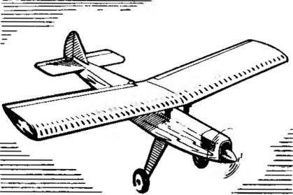 Despite the popularity of radio controlled model airplanes-srednevekov, the attention of designers-modelers often drawn to the now obsolete scheme. And this is understandable — after all, the “big” aviation, such machines include a spectacular cabin aircraft, starting with the domestic Yak-12 and ending with dozens of options American Cessna.