 Motomobile is an individual vehicle, in which, as the name implies, combines the qualities of car and motorcycle. Needless to say, unite the advantages of these vehicles with the greatest possible exclusion of their shortcomings.
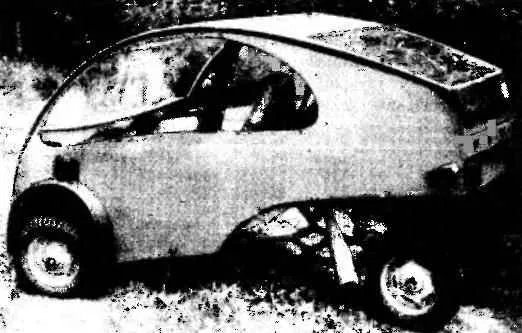
“Ruta” — is extremely simple, very comfortable, highly economical and inexpensive to manufacture machine designed for individual use as a city or a car, and cars for truckers, capable of carrying a driver with a passenger and not too bulky Luggage. Fits well as “Rue” as a vehicle for the disabled and the elderly.
As already mentioned, motomobile can carry two people with Luggage up to 40 kg with a speed of 60 km/h. fuel Consumption is 4.2 l per 100 km.
The design of the machine was based on the ergonomic principle known as the core vehicle is selected the driver or the passenger… along with comfortable car seats. Geometric parameters of such kernel become the core when drawn sufficiently spacious shell — cases of the future vehicle. Of course, this is the most efficient location of the major components and assemblies of the machine. The result of such a construction form shell turned out egg-shaped (in lateral view), with the greatest strength of the rational ratio between the volume and the full surface. This form, in addition, has a low aerodynamic resistance, but it can be even reduced if the body is somewhat elongated in the direction of motion and is narrowed in its rear part.
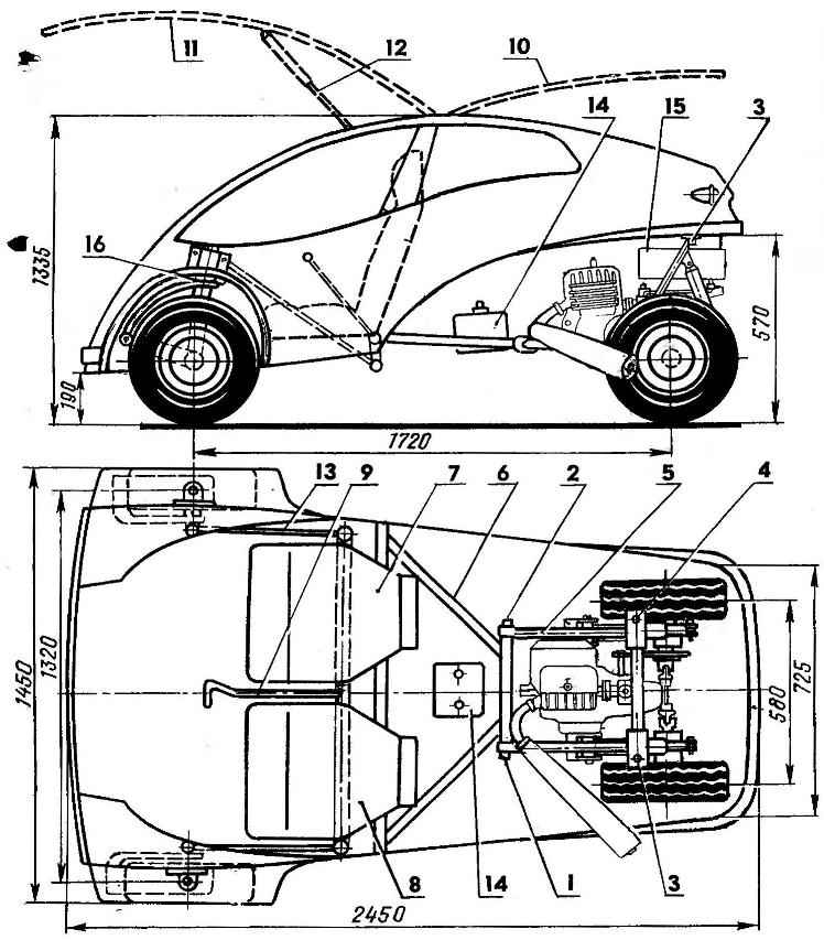
Fig. 1. The layout of the motomobile “Ruta”:
1,2 — nodes of the sub-frame mounting of power plant,
3, 4 — bolts securing the rear of the subframe,
5 — subframe power plant,
6 — frame of motomobile,
7 — passenger seat,
8 — the driver’s seat,
9 — steering arm,
10 — tailgate
11 — the door
12 — the locking door,
13 — tie rod,
14 — batteries,
15 — fuel tank,
16 — pivot strut of the front wheel.
Layout of machines unconventional. Its body has no doors to enter the car the hatch is provided in the front part, the lid of which forms a wall of the body with part of its roof. Such lifting door allows to enter the machine almost without bending, which is especially important for people with disabilities and the elderly. Similarly constructed lid — it also folds up. As can be seen from the drawings, this cover is virtually horizontal, so to improve visibility it has a large area of glazing.
The four-wheeled car, it is designed for a symmetric scheme with steered front and spaced rear driving wheels. This scheme has a number of advantages over traditional: in particular, allows to make the machine lighter, more technologically advanced and inexpensive to manufacture, is quite maneuverable, while maintaining sufficient stability.
To reduce noise inside the cabin and entering the fuel vapor, oils and exhaust all the units of motomobile are located outside the capsule of the cab. To all, this allows to simplify the maintenance of the machine.
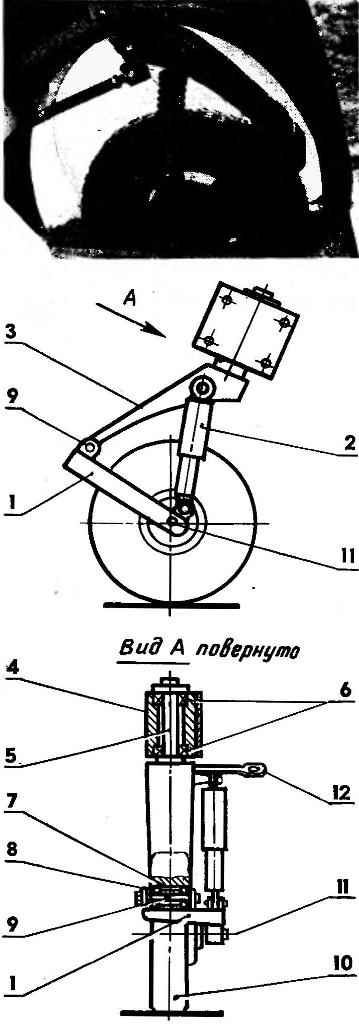
Fig. 2. Swivel front front wheels:
1 — longitudinal oscillating arm,
2 — shock absorber (heavy or medium motorbike)
3 — swing arm stand,
4 — Stacey,
5 — axis swing arm rack
6 — angular contact ball bearings,
7 — bushing,
8 — bearing,
9 — axle trailing arm suspension
10 — front wheel of motomobile,
11 — wheel axle,
12 — fist.
Front steer wheel mounted together with swivel racks and pendants on the sides of the body of motomobile. Rear wheel together with the power unit form a single unit located in the rear of the machine.
Front suspension and principle of management borrowed from the aircraft — almost as arranged operated landing gear. “Rute” left and right suspension designed according to the scheme of the longitudinal swinging lever and the external hydraulic shock-absorber medium or heavy motorcycle. The main power element of such a stand is a swivel lever, which is welded to the axle, mounted in glass on two angular contact bearings. In the lower part of the swinging arm is welded a sleeve in which the two bearings of the hinged axis of the longitudinal control arm. At the end of this lever is fixed the axis on which rotates the front wheel. In the upper part of the lever is welded fist with which the entire stand can be rotated around its axis. Characteristically, the rotary lever and the front wheel are located in the same plane — this allows you to make wide wheel minimum.
R and S. 3. Steering system the motomobile (A — with a single arm, B — with two arms):
1 — steering arm,
2, 3 — left and right steering levers
4 — swivel shaft,
5, 6 — levers of the rotary shaft,
7, 8 — left and right tie rods,
9, 10 — right and left fists
11, 12 — left and right swivel,
13, 14 — left and right hinge joints pivot arm stand,
15, 16 — a pair of cylindrical gears.
Front suspension and wheel are separate Assembly unit and mounting it is made out of motomobile, separately. And even after Assembly of the complete site by using bolts and nuts fixed on the body and a closed mud flap.
The steering system on the “Rut” is different from the classic. The fact that the use of conventional steering linkage on the motomobile would lead to excessive pereplonennyh the front, and the presence of the steering wheel would have made the landing in motomobile and out of it. The more that motor vehicle, which, in essence, is “Ruth”, can be equipped with more simple and cheap motorcycle controls.
The solution found for the steering control of motomobile, is not very different from a motorcycle, especially when used to control two arms. In fairness it should be noted that control of the car and one hand — this option is particularly interesting for disabled people.
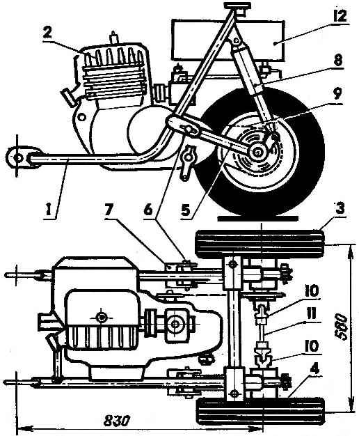
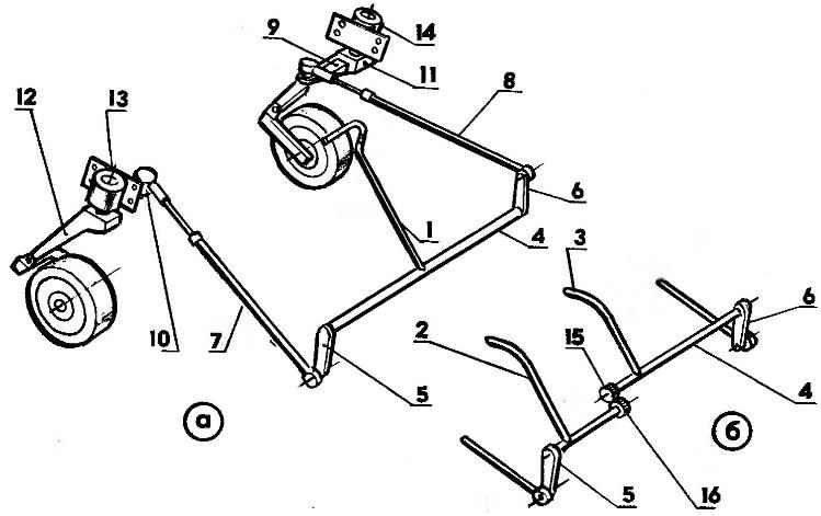
Fig. 4. The power unit motomobile:
1 — frame,
2 — engine, T-200M,
3, 4 — right and left wheels of the power unit,
5 — trailing arm suspension wheel
6 — axis,
7 — eyelet
8 — shock absorber (medium or heavy motorcycle),
9 — chain drive rear wheels,
10 — hinges Hooke,
11 — connecting shaft.
The figures show two variants of a control system with two arms and one. In the second embodiment, power transmission from the crank to the wheels is through installed at a rotary shaft, and then through two levers, welded on the ends of the shaft, the effort is transmitted to left and right thrust, which connect respectively with fists left and right of the rack. At the same stand with the wheel and suspension is rotated by the angle proportional to the angle of deflection of the control lever machine. Thrust connected with the levers and punched with the ball studs; traction also have the ability to adjust their length to adjust the toe angle of the wheels. Adjustment of the angle of rotation of the wheel is achieved by the selection of the angles of the levers relative to each other.
The version control system with two steering levers — requires the use of a split rotary shaft, half of which are kinematically connected to each other by a pair of cylindrical gears. In this case, each control arm is welded respectively to the right or left polumalu end levers will be pointing in the same direction (down). The use of a notched compound semi-shafts allows them synchronously rotated in mutually opposite directions in accordance with movement of the steering levers.
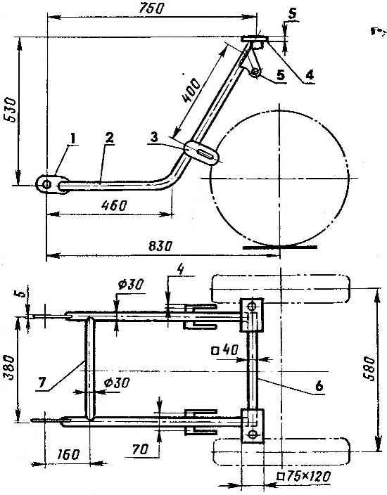
Fig. 5. Subframe:
1 — the eye (steel strip with a thickness of 5 mm),
2 — side rail (steel pipe with a diameter of 30 mm),
3 — plug,
4 — basic platform (steel strip with a thickness of 5 mm),
5 — the top support of the shock absorber (steel strip 4 mm thick)
6 — rear cross bar (square steel pipe),
7 — front cross member (steel pipe with a diameter of 30 mm).
Used for “Rute” the steering mechanism is structurally simple and, importantly, allows the driver to operate the Moto-cart-motor, directly, without any transmission mechanism. Accordingly, the load on the steering arms does not exceed the load on the handlebars of the motorcycle with a lateral trailer — this is due to the small mass of motomobile and a small wheelbase.
It should be noted that the “Rute” is easily mounted and conventional steering wheel, with its shaft and the steering gear are connected almost the same as that already described for the lever of the steering mechanism.
Non-traditional designed for “Rute” and the power unit. As mentioned above, the engine, transmission and rear-wheel represent a single unit mounted on a special subframe. The base powerplant is a two-stroke engine working objmon 200 CC with a power of 14 HP from scooter “Tourist”. The engine is mounted on the subframe between the two rear wheels. The latter is suspended from the subframe trailing arms, swinging on axes fixed in the eyes. As the elastic elements of the suspension used Motorcycle shock absorbers.
The drive from the engine is carried out using roller motorcycle chains only on the right wheel. The left wheel is connected with the right with a shaft and a pair of Hooke’s joints.
 The rear track is chosen equal to 580 mm with wheels with a diameter of About 460 mm allows to do without a differential, the slip of the wheels when turning is insignificant.
The fuel tank is mounted at the top of the subframe between the rear wheels. The flow of the fuel mixture in the carburetor of the engine is by gravity, as in any motorcycle. In order to protect the engine against ingress of dirt and water, wheel mud flaps are closed.
As mentioned above, the power unit is a separate Assembly unit that includes engine, drive, suspension, wheels and fuel tank. This whole Assembly is going on the stretcher and then secured in the rear part of the body of motomobile, two joints of his frame, At the top of the power unit attaches with a pair of easily removable bolts with nuts and washers. This mount allows the power unit to service and repair it without disconnecting it completely from the car, but only raising its tail part is the upper bolts of the engine needs to be rejected.
Power block “Rue” can be used independently — for example, as the basis of walk-behind or as mototech for trolley or other agricultural implements.
Recommend to read
 SO THE RESEMBLANCE WAS COMPLETE
For the manufacture of parts for models of artillery and torpedo armament of the marine models usually spent a lot of time, it is not always possible to achieve full similarity. Some of... A QUARTER OF A CENTURY IN THE RANKS
Bomber-attack aircraft A-26 INVADER. If you ask aviation experts to name the most well-known plane-survivor, then some of them will remember a passenger DC-3 by Douglas, the other a...
