OLD BIKE – NEW WALK-BEHIND

OLD MOTORCYCLE - NEW WALK-BEHIND TRACTORDuring design development we present motoblock tried to solve three tasks. First, maximum use of to manufacture standing for several years without case motorcycle “Minsk”. Secondly, to be able to make at home, with minimal turning and without using expensive parts. Finally, third, we wanted to make a walk-behind tractor, which would be a good mechanical helper in the household with a plot of land: that it was earth to plow, potatoes and other root vegetables to plant, inter-row cultivation of plants run, and the harvest be removed and relocated.

The tillers turned out pretty good, it met expectations and tested to work in severe conditions.


Began production of walk-behind tractor with alterations of the base frame of the motorcycle “Minsk”. From the frame sawed off unnecessary in the future and hindering the work of the various brackets, footrests passenger, and a left footrest for the driver. Right footrest of the driver cut at a distance of approximately 180 mm from the axis of the under engine pipe (the plane of symmetry of the frame). The remainder were used as the bracket of the muffler. And here is the seat bracket off only after it has been welded to the frame steering levers with their connecting cross-bar, curved as one piece of half-inch pipe.


With great responsibility reacted to the manufacture of the bearing sleeve of the drive shaft of the wheel, its mounting and securing on the frame of the cultivator. It would be better to make the bushing one-piece on a lathe from 300-mm cut steel thick-walled pipe or round steel with a diameter of 60 mm. We, in the absence of such blanks, have used a welded construction made from matched to each other, cuts steel seamless pipes of appropriate sizes and lengths (by the way, the same technology is made and sleeve of the intermediate shaft). While sections of tube with large diameter to form a socket under 80205 deep groove ball bearings with two shields (you can use bearings 60205 — factory with one protective spacer from dust-dirt (only need to install it necessarily outside).

For the bearing sleeve has prepared a place — a small curved cutout under the bottom tube of the frame at the junction of the racks. The sleeve is mounted perpendicularly to the Diametric plane of the frame so that its middle lying in this plane, and only “taking” and adjusted, welded this important site to the frame permanently.

The tillers from the old bike (the units and components POS.6,8,9,10,13—a motorcycle


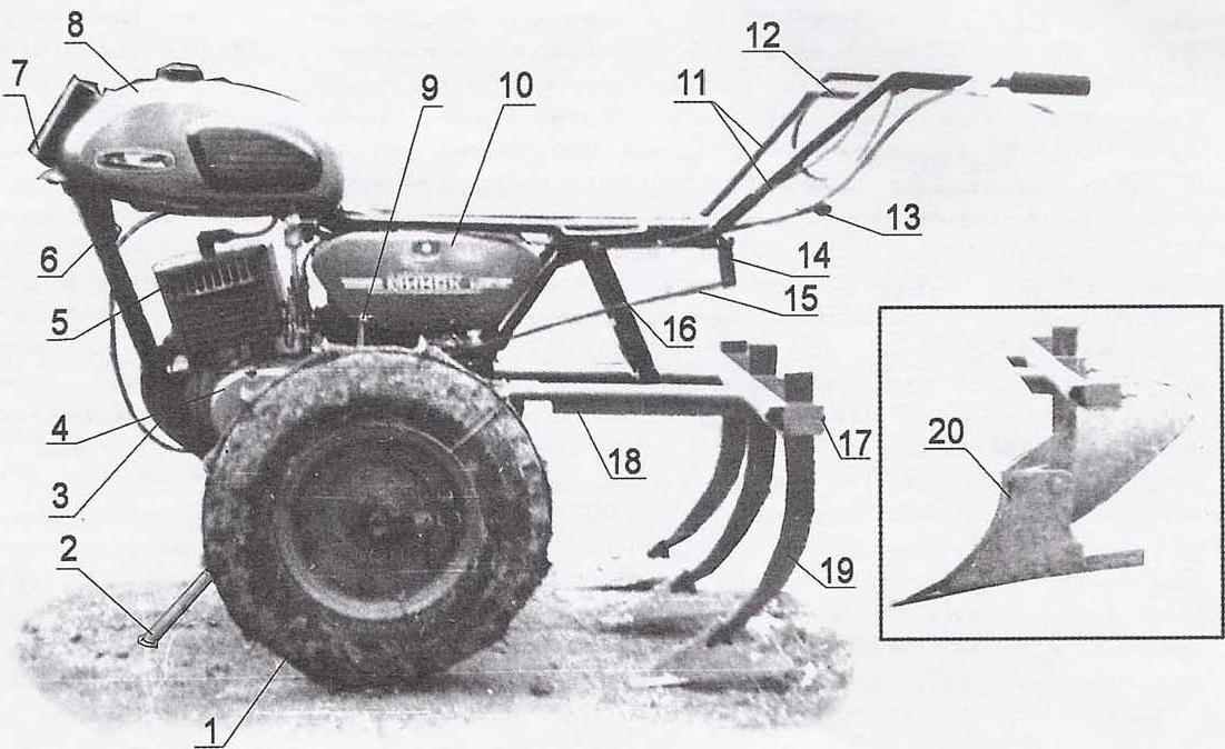
The tillers from the old bike (the units and components POS.6,8,9,10,13—a motorcycle “Minsk”):

1 — wheel with grousers (farm equipment, 2 PCs.);

2 — Parking time;

3 — exhaust pipe with silencer;

4 — power unit (from a motorcycle “Minsk”);

5 — cylinder head cover with forced air cooling;

6 —frame tillers (modified);

7 — column;

8 — gas tank;

9 — kick-starter;

10 — storage box tools and accessories;

11 —lever controls;

12 — crossbar levers;

13 — lever-gear shift grip;

14 — rocking chair;

15 — pull shifter;

16 — U-shape suspension fixing frame mounted implements;

17 — cross member for the mounting of the guns;

18 — frame attachments;

19 —cultivator;

20 — plow.


In the back of the “Minsk” of the frame are brackets with holes 8 mm diameter for attachment of the mud flap (wing). These several brackets are bent inside of them straightened, made parallel to the longitudinal plane of the frame of the cultivator. Then the reinforced brackets welded to the pipes and steel strips with a cross-section 20×5 mm. Holes in the brackets drilled to a diameter of 10.2 mm.


After amplification, the ends of the brackets and arcs upper seat frame welded control levers carried out with the crossmember (bent and welded in the bends) of half-inch steel pipe. Tried to weld symmetrically relative to the plane of symmetry of the frame, and the ends of the levers lit, so they were at a distance of about 780 mm from each other. After that, the levers were inserted and welded to the corresponding spacer.
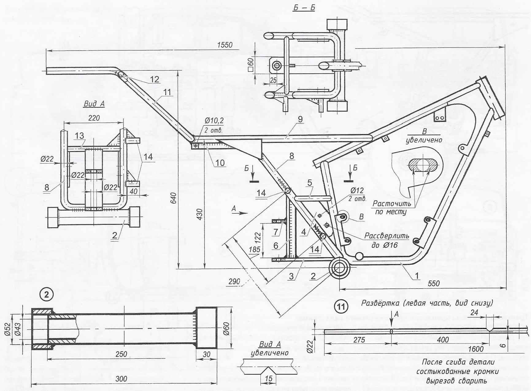
Frame walking tractor


Frame walk-behind:


1 — motor mount (from a motorcycle “Minsk”);

2 — bushing drive shaft of the wheels (steel, circle 60);

3 console (steel, strip 60x7x210);

4 — cheek (steel, sheet s5, 2 PCs.);

5 connection (steel pipe 1/2″);

6 — t-stand (weldment of two strips with section 60×7);

7 — pivot bracket-lug (steel, strip 60x60x7);

8 — strut strut;

9 — seat arc;

10 — bracket-stiffener (steel, strip-section 20×5,2);

11 — bellcrank steering with tie bar (steel pipe 1/2″);

12—strut steering arms (steel pipe 1/2″);

13 — insert (steel pipe 1/2″);

14 — suspension brackets intermediate shaft and mechanisms chain tension (pipe 1/2″)


The l-shaped lever-handle manual gear shift is bent from a steel 10 mm rod. Wearing her short (length 12 mm) remote arm bushing is inserted from the right side (if you focus on a course of movement of the motor-block) into the holes of the brackets with the welded strips. And the left side on its end fits over another of the same remote, the hub and welded to the chair with a hole diameter of 8.2 mm for thrust. Pull (wire diameter 8 mm) connects the rocking lever and the gear shift mounted on the shaft of the transaxle.


For connection to the tillers of the trolley frame is welded by node coupling. It is made from strips of steel strip with section 60×7 mm and consists of a horizontal console and stand, reinforced stiffener. The rear end of the console in favour of the rack for 60 mm, and to the rack at a height of 122 mm is welded to a lug corresponding to lug the console. In both parts are drilled coaxial holes with a diameter of 22 mm. Between them is inserted the bushing drawbar truck (120-mm section of steel pipe with inside diameter 22 mm) and the node is coupled by drawbars.

Intermediate shaft Assembly with the stars


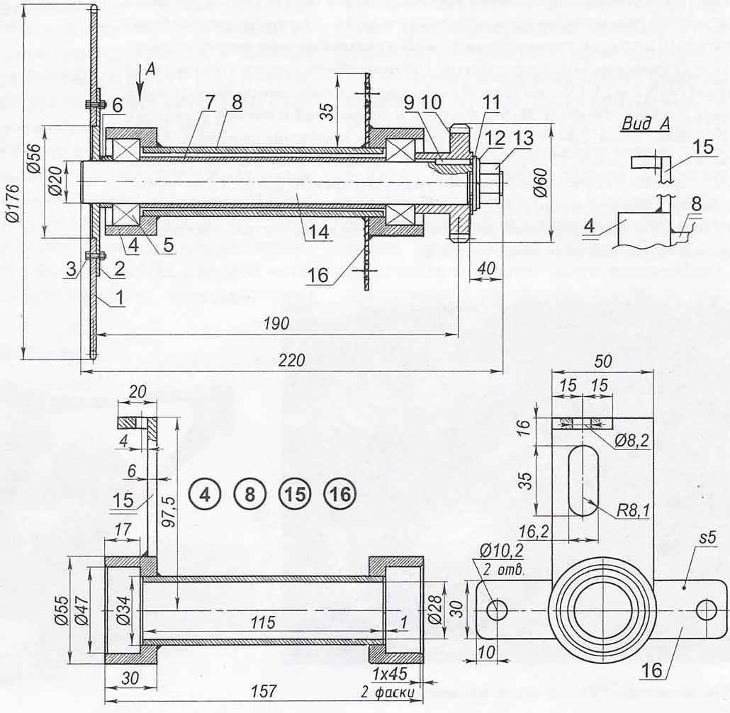
Intermediate shaft Assembly with the sprockets:

1 — sprocket z=42 (from a motorcycle “Minsk”);

2 — hub (FT4);

3 — mount the sprocket to the hub (M5 screw, 6 PCs);

4 — the bearing housing (FT4, 2);

5 — deep groove ball bearing 80204 with protective washers (2 PCs.);

6 — short spacer (steel tube 3/4″);

7 —long spacer (steel tube 3/4″);

8 — piece intermediate shaft (weldment, pipe 34×28);

9 — key 5x5x20 (STB);

10 — sprocket z=8, was designed together with the hub (Steel 45);

11 —washer (ft3);

12 — spring split washer;

13 —mount sprocket (nut M14);

14 — intermediate shaft (Ст6);

15 — mounting bracket the intermediate shaft to the frame (steel sheet s6, 2 PCs.);

16 — brackets chain tension (steel sheet s5, 2 PCs.)


Powertrain and drivetrain the bike was designed for speed up to 85 km/h (up to 5500 rpm) that for a “garden” of the machine was completely useless. So the transmission had to introduce intermediate shaft with two lower chain gear in order to reduce the number of revolutions of 13.5% and significantly increasing “tegometall” motoblock. The right rear strut to the front of the frame (if you focus on a course of movement of the tillers), departing from the axis of the sleeve of the drive shaft 105 mm, is welded to the first tube bracket perpendicular to the plane of the frame, and stepping back 185 mm — another of the same tubular bracket (mounting) of the intermediate shaft.

In brackets the fingers are inserted into the threaded rods and the holes in the fingers themselves skipped the ends of the threaded rods of the tensioning chain drive second stage. These fingers and thrust as stretching, support the right end of the intermediate shaft. Fingers in tubular brackets are held by friction.

Transmission and the attachment points of the intermediate shaft to the frame

Transmission and the attachment points of the intermediate shaft to the frame


Transmission mounts intermediate shaft to the frame:

1 — sprocket output shaft of the power unit;

2 — the first circuit stage;

3 —a large sprocket of the intermediate shaft with the hub;

4 — an intermediate shaft;

5 — small sprocket of the intermediate shaft;

6 — circuit of the second stage;

7 —an asterisk of a drive shaft of the wheels with the hub;

8 — drive shaft with lever lock wheels;

9 — cotter pin hub sprocket, drive shaft and drive wheel;

10 — driving wheel;

11 — strut strut frame;

12 —bushing drive shaft;

13 — bushing the intermediate shaft;

14 — bracket intermediate shaft (2 PCs.);

15 — finger threaded thrust suspension of the intermediate shaft;

16 is a vertical threaded M10 suspension pull the intermediate shaft and the tension of the chain second stage;

17 connection of threaded thumb bracket intermediate shaft (M10,2 PCs.);

18 —mount the l-bracket, intermediate shaft to cheek (specmat M16 with flat and spring washers and nut);

19 — cheek frame;

20 l — shaped bracket intermediate shaft to the cheek frame;

21 —threaded pull tension of the first stage;

22 — fastening and locking of the threaded pin (M10 nut,5 PCs.);

23 — finger hinge frame of the equipment;

24 — nut M10 chain tension transmission (4 PCs.);

25 — horizontal thrust threaded M10 suspension of the intermediate shaft and chain adjustment of the second stage.


The lower hole in the right cheek, where before you insert the axis of the pendulous fork of the motorcycle, to reams of 16 mm diameter. This is a place holding a large G-shaped bracket intermediate shaft Assembly. As the fastener here is 40 mm M16 bolt inserted in the groove of the bracket and the hole in the right cheek from the inside. Outside it is enclosed by respective flat nut (4 mm thick) and spring washer. Inside the bolt holding turn-precise fit (tight fit) faces of the bolt head to the threaded end of the foot thrust as a mechanism tensioning the chain first stage. Thrust is inserted into the hole of the shelf bracket from the hull of the intermediate shaft and tighten the nut.


Transmission with intermediate shaftAs for the upper hole with a diameter of 12 mm at the cheeks, they are used for loading shaped bolts that are hooked to the hooks frame mounted implements. Here the bolts are firmly tightened nuts with lock washers.

In the front part of the frame of the cultivator is set to “regular” mounting brackets power unit of the motorcycle “Minsk” (MMVZ-C 115). The holes in the brackets are wasted in the slots for additional adjustment of the tension of the chain transmission. And 10-HP engine does not overheat even during continuous operation at low speeds and under heavy loads, on the right mounted fan forced air cooling for cooling the cylinder and head. The latter turned 90° counterclockwise compared with the standard position.


A fan mounted on the extension of the rotor shaft of the generator. For this used a long threaded bolt M7 at the end, spring washer, extension sleeve with two pins, made of 3 mm the spokes of a wheel from a motorcycle М105 “Minsk”, and compresses the impeller from both sides of the special washers with an outside diameter of 30 mm. Below the extension sleeve can pass through the lid of the generator, the latter drilled strictly coaxially to the rotor shaft hole with a diameter of 17.5 mm. there is a seal, made of 5 mm felt.


In addition, the rotor had to drill a recess (blind hole) depth 6.5 mm and a diameter of 3.3 mm under the pin extension sleeve. The other pin is inserted into the impeller and serves as a key.

Control systems walk-behind and shift


Control system, tillers and gear:

1 — l-shaped lever-handle shifter;

2 — rocking chair;

3 —pull;

4 — bracket;

5 — regular shift lever;

6 —kick-starter;

7 — the lever of deenergizing of coupling;

8 — arm “gas”.


Fan housing is collapsible. Consists of the upper part, which is the duct, and the lower is intake. Both parts of the roofing is made of 0,8 mm steel sheet for the respective scans, and are connected by rivets 3 mm aluminum wire (two rivets on one link).


The air intake is attached to the cover of the generator with two bolts M6 turnkey 10 mm (extra long by 15 mm compared to the former). But not closely, and through the spacer. Under the head bolts and put a regular washer.

Cover the air intake is removable, is fastened to the bottom bolt MB. The top of the cap is held by the limb of the duct.


Held together the two parts of the casing to each other with two bolts M6, and the cheeks of the duct are tightened on the cylinder by a spring, for which they made holes with a diameter of 2 mm.

The silencer


Muffler:

1 — breather tube (from a motorcycle “Minsk”);

2 — bracket (St3, strip section 20×5);

3 — flange (Steel 25);

4 — fasteners (screw M4 6 PCs.);

5 — the case (from a motorcycle “Minsk”);

6 — gazoperepusknogo pipe (pipe from the frame of the Bicycle the “Ural”) with 4 getproductname and 4 mounting holes;

7 — end cap (Steel 25).


As already stressed, for the best blowout of the cylinder head turned 90° counterclockwise. Round cover that covers the worm clutch, cut in the shape of the bending of the side wall of the air intake for tight connections. Now this is twisted of the cap on one bolt with spring washer.


Lever kickstarter straightened to a right angle (the slots are perpendicular to the lever and parallel to the foot) — it’s more convenient to start the engine: it became more space for legs. To the shift lever at a slight angle welded bracket made of flat steel section 20×7 mm, to which is attached a rod shifter.

Hinged frame guns


Frame attachments:

1 — hook (steel, sheet s5, 2 PCs.);

2 — side rail (steel pipe, 2 PCs.);

3 —the main cross bar (steel pipe 1/2″);

4 is an additional cross — member (steel angle 50x50x5);

5 — socket attachments (from steel strip 50×6 mm, 3 PCs.);

6 — a stopper knot attachment tools (nut M10 welded, 3).

7 — Klondike solitaire (steel, sheet s5, 2 PCs.);

8 — rib (steel strip 300x20x5, 2);

9 — bracket (steel threaded rod M12);

10 — U-shaped bracket fixing frame mounted implements on the cultivator.


Silencer homemade. His body used the pipe of the muffler of the motorcycle “Minsk”. Back, inside the flared end of the nozzle is aligned on inch steel pipe to the diameter of the rest part. Then set in its place a homemade box with an outlet tube and fixed by two screws M4. As shown, this “stuffing” significantly reduces noise when the engine is running.


To the discharge pipe welded a bracket to the right footrest of the driver, which at a distance of 10 mm from the end of the drilled horizontal through hole with a diameter of 8 mm. the Length of the bracket and position it on the outlet tube defined by place.

Kinematic scheme of transmission


Kinematic scheme of transmission:

1 — power unit;

2 — output shaft of the power unit;

3 — sprocket output shaft (z1=14, t=12,7);

4 — circuit 1-th stage (t=12,7);

5 — large intermediate shaft sprocket (z2=42; 1=12,7);

6 — intermediate shaft;

7 — bushing the intermediate shaft;

8 — intermediate shaft bearing 80204 (2 PCs.);

9 — small sprocket of the intermediate shaft (zЗ=8,1=19,05);

10 — chain 2-th stage (t=19,05);

11 — sprocket drive shaft (z4=39, t=19,05);

12—drive shaft;

13 — driving wheel;

14 —bushing drive shaft;

15 — the bearing of the drive shaft 80205 (2 PCs.);

16 — the locking mechanism;

17 — locking wheel;

18 —bearing lockable wheels 80205 (2 PCs.)


Z1 sprocket (14 teeth), z2 (42 teeth) and the chain of 12.7 PR — a motorcycle “Minsk” (ММВ33.112). But zЗ (8 teeth) — a homemade, designed to work with chain 19,05 PR. The workpiece for the stars (without a Central hole with a diameter of 20 mm at the shaft) machined on a lathe. On a drill press parallel to the axis performed a 5 mm hole under the key. Then again on the lathe drilled in the billet Central (axial) hole with a diameter of 20 mm. by Clicking again on the drill press, got subgeometric eight equidistant holes. To the desired configuration, the sprocket teeth brought first a hacksaw, then a file. The remaining protertye under the key modified with a needle file to the rectangular groove. Finally, the asterisk was subjected to hardening: heated it in the flame of a gas burner and sharply cooled in water.


Asterisk z4 — 39-bevel with a pitch of 19,05 mm from the combine harvester SKR-6. It is seated on the drive shaft of the wheels so that the plane of rotation of its sprocket and the small intermediate shaft strictly coincide. With the shaft of the sprocket hubs are connected to the cylindrical pin with a diameter of 7 mm, inserted into pre-drilled simultaneously in both parts diametrically corresponding hole.

Sleeve lock mechanism left wheel


Wheels with tires size 5.00-10″ from used agricultural machinery. Leading is the right wheel. In its hub instead of the bearing bushing is inserted. Hub with bushing and shaft tillers drilled through the diameter of the drill bit with a diameter of 7.9 mm when tightened the shaft nuts. After that, the hole is pressed pin — straight (without a hat) rod with a diameter of 8 mm and a length of 90 mm, made of engine valve of a car “Moskvich”. Advance the pin is 3 mm from its end outlined by the core and drilled a hole with a diameter of 3 mm in order to subsequently insert the cotter pin out of a nail. The other end of the pin is left behind after pressing to protrude above the hub of about 15 mm, heated from the end with a blowtorch and a hammer formed from his head.


The left wheel is mounted on two radial ball bearings 80205, closed additionally cuffs (the same wheel).

The site of the Central shaft having a maximum diameter of 31 mm and is located between the inner bearing of the left wheel and the carrier bearing sleeve (which is welded to the frame tillers), closed 3-mm thickness of the washer serving as a unique seal.

the lock mechanism, having a length of 15 mm greater than the radius of the circle on which the centers of the holes in the discs bolt left wheel.

Lock left (in the direction of the motor-block) wheel is required. To do this, stop the walking tractor, it is enough to enter into engagement with the lock bracket (welded, as already indicated, to the drive shaft) special nut. The latest from cut half-inch steel pipe, one end of which is sliced inner thread corresponding to the threaded pins (M16) connecting the wheels, and near the other end is drilled diametrically hole under the knob of the 200-mm nails (or steel wire with a diameter of 6 mm). Sleeve is screwed onto one of the studs instead of nuts. After screwing on the knob sleeve of her should be removed.

Items fan air cooling cylinder

Items fan air cooling cylinder


Details fan-cooled cylinder:

a — impeller (aluminum sheet s1,2);

b —mount the impeller to the magneto (specmat M7);

in — gear impeller Bush with pin (specmat M7);

Mr. washer ;

d — upper part of the casing;

e —the lower part of the casing;

W — cover the air intake.


Crimp ring lugs and fixing them on the wheel bracket is made of lengths of steel strips cross-section 20×4 mm. Strip 10 mm shorter than the circumference of an inflated tyre, their ends are welded butt joint with 60 mm overlay. 100 mm lugs are welded to the rings 12 pieces at equal intervals. In every fourth grundsatze (through 120°) in 15 mm from their edges are made of threaded holes M8. They screwed up to the stop heads of the corresponding screws protruding from the rear (in the direction) side of approximately 20 mm outward. The screw heads are welded to grundsatzen. Ring with this “climax” fills the hammer at half-mast-wheel to the middle of the tyre. Then on the screws are worn hooked over the rim flange of the bracket, pre-cut made of the same steel strip with 8-mm hole in the top (twisted 90°) parts and secured using nuts with lock nuts. The pressure in the chambers of the wheels increase to normal to the rings and brackets are firmly compressed his tire.


Handle “gas” is adapted from the motorcycle M-105 “Minsk”. Clutch lever from a motorcycle IZH-7.107 “planet-5”.


Frame mounted implements quick. The hooks are fixed on the fitting bolt spring-loaded t-shaped bars made from steel strip. The frame itself is in working and transport position, is held a U-shaped comb. Nests for installation of attachments on rear crossmember designed for the serial risers of the tractor of the cultivators.


The arcs on the seat frame if needed, you can consolidate small cargo box (a pound) for transportation over short distances of vegetables and root crops or small-size cargoes weighing up to 50 kg.


Good painting fuel tanks, tanks for storage of tools and accessories, frame mounted implements, casing fan forced cooling and drive wheels attached to the cultivator-laborer factory. Many do not even believe that the cultivator is hand made. About the reliability of this mechanical assistant and can not speak — the key to the simple design.


The main characteristics of the tillers

Overall dimensions (length x width x height), mm — 1600x820x900

Track width, mm — 680

Ground clearance, mm — 250

The power plant of the motorcycle “Minsk”

Engine power, HP — 10

Working speed

(when plowing to a depth of 250 mm), km/h — 2

Transport speed

(with tow truck), km/h — 30

Load capacity, kg — 500


E. FEOFILAKTOV, settlement NEMA, Kirov.

Recommend to read

  • TELL ME… SHADOWTELL ME… SHADOW
    In any workshop is the most convenient way tool storage — placing them on a wall stand: and immediately visible, and easily accessible. However, returning after use, is easily confused...
  • GASOLINE IS NOT NEEDEDGASOLINE IS NOT NEEDED
    I built most of the vehicles are based on commercially available motorcycle or bike noisy and power hungry internal combustion engines. It was with one hand comfortably, and the other is...